
OPERATION AND INSTALLATION
OPERACIÓN E INSTALACIÓN
OBSLUHA A INSTALACE
OBSŁUGA I INSTALACJA
RUKOVANJE I INSTALACIJA
COMANDĂ ȘI INSTALARE
РАКУВАЊЕ И ИНСТАЛАЦИЈА
ОБСЛУЖВАНЕ И ИНСТАЛИРАНЕ
ЭКСПЛУАТАЦИЯ И УСТАНОВКА
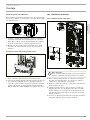
Electronically controlled comfort instantaneous water heater| Calentador
instantáneo de confort con regulación electrónica| Elektronicky regulovaný
komfortní průtokový ohřívač| Elektronicznie regulowany komfortowy przepływowy
ogrzewacz wody| Elektronski regulisan komforni protočni grejač| Încălzitor
instant confort reglat electronic| Електронски регулиран удобен проточен бојлер|
Електронно регулиран комфортен проточен бойлер| Проточный водонагреватель повышенной
комфортности с электронной системой регулирования
» PEY 18/21/24
Made in Germany
30
60
45
35
40
50
55
°C

2 | PEY www.stiebel-eltron.com
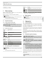
CONTENTS | SPECIAL INFORMATION
SPECIAL INFORMATION
OPERATION
1. General information �����������������������������������������3
1.1 Safety instructions ����������������������������������������������� 3
1.2 Other symbols in this documentation ����������������������� 3
1.3 Units of measurement ������������������������������������������ 4
2. Safety ���������������������������������������������������������� 4
2.1 Intended use ������������������������������������������������������ 4
2.2 General safety instructions ������������������������������������ 4
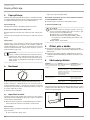
3. Appliance description ���������������������������������������4
4. Settings �������������������������������������������������������4
4.1 Recommended settings ���������������������������������������� 4
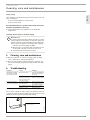
5. Cleaning, care and maintenance ���������������������������5
6. Troubleshooting ����������������������������������������������5
INSTALLATION
7. Safety ���������������������������������������������������������� 6
7.1 General safety instructions ������������������������������������ 6
7.2 Shower operation������������������������������������������������ 6
7.3 Instructions, standards and regulations �������������������� 6
8. Appliance description ���������������������������������������6
8.1 Standard delivery ������������������������������������������������ 6
9. Preparation ���������������������������������������������������6
9.1 Installation location ��������������������������������������������� 6
9.2 Water installation ������������������������������������������������ 7
10. Installation ����������������������������������������������������7
10.1 Standard installation �������������������������������������������� 7
10.2 Alternative installation methods����������������������������� 10
10.3 Completing the installation �����������������������������������12
11. Commissioning ��������������������������������������������� 12
11.1 Initial start-up ��������������������������������������������������� 12
11.2 Recommissioning �����������������������������������������������13
12. Appliance shutdown ��������������������������������������� 13
13. Troubleshooting �������������������������������������������� 13
14. Maintenance ������������������������������������������������ 14
15. Specification ������������������������������������������������ 14
15.1 Dimensions and connections ��������������������������������� 14
15.2 Wiring diagram ������������������������������������������������� 15
15.3 DHW output ������������������������������������������������������ 15
15.4 Application areas/ Conversion table ����������������������� 15
15.5 Pressure drop ��������������������������������������������������� 15
15.6 Fault conditions ������������������������������������������������� 15
15.7 Test symbols ����������������������������������������������������� 15
15.8 Energy consumption data ������������������������������������� 16
15.9 Data table �������������������������������������������������������� 16
GUARANTEE
ENVIRONMENT AND RECYCLING
SPECIAL INFORMATION
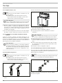
- The appliance may be used by children aged3
and older and persons with reduced physical,
sensory or mental capabilities or a lack of ex-
perience and know-how, provided that they
are supervised or they have been instructed
on how to use the appliance safely and have
understood the potential risks. Children must
never play with the appliance. Children must
never clean the appliance or perform user
maintenance unless they are supervised.
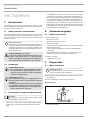
- The tap can reach temperatures of up to
60°C. There is a risk of scalding at outlet tem-
peratures in excess of 43°C.
- The appliance is suitable for supplying a
shower (shower operation). If the appliance
is also or exclusively used for shower oper-
ation, the qualified contractor must activate
the temperature setting range using the
temperature limit (Tred = 55°C) in the appli-
ance. When using preheated water, it must be
ensured that the inlet temperature does not
exceed 55°C.
- Ensure the appliance can be separated from
the power supply by an isolator that discon-
nects all poles with at least 3mm contact
separation.
- The specified voltage must match the mains
voltage.
- The appliance must be connected to the earth
conductor.
- The appliance must be permanently connect-
ed to fixed wiring.
- Secure the appliance as described in chapter
"Installation/ Installation".
- Observe the maximum permissible pressure
(see chapter "Installation/ Specification/ Data
table").
- The specific water resistivity of the mains
water supply must not be undershot (see
chapter "Installation/ Specification/ Data
table").

OPERATION
General information
ENGLISH
www.stiebel-eltron.com PEY | 3
- Drain the appliance as described in chapter
"Installation/ Maintenance/ Draining the
appliance".
OPERATION
1. General information
The chapters "Special information" and "Operation" are intended
for both users and qualified contractors.
The chapter "Installation" is intended for qualified contractors.
Note
Read these instructions carefully before using the appli-
ance and retain them for future reference.
Pass on the instructions to a new user if required.
1.1 Safety instructions
1.1.1 Structure of safety instructions
!
KEYWORD Type of risk
Here, possible consequences are listed that may result
from failure to observe the safety instructions.
Steps to prevent the risk are listed.
1.1.2 Symbols, type of risk
Symbol Type of risk
Injury
Electrocution
Burns
(burns, scalding)
1.1.3 Keywords
KEYWORD Meaning
DANGER Failure to observe this information will result in serious
injury or death.
WARNING Failure to observe this information may result in serious
injury or death.
CAUTION Failure to observe this information may result in non-seri-
ous or minor injury.
1.2 Other symbols in this documentation
Note
General information is identified by the adjacent symbol.
Read these texts carefully.
Symbol Meaning
Material losses
(appliance damage, consequential losses and environmen-
tal pollution)
Appliance disposal
!
!

OPERATION
Safety
4 | PEY www.stiebel-eltron.com
This symbol indicates that you have to do something. The ac-
tion you need to take is described step by step.
1.3 Units of measurement
Note
All measurements are given in mm unless stated oth-
erwise.
2. Safety
2.1 Intended use
The appliance is intended for domestic use. It can be used safely
by untrained persons. The appliance can also be used in non-do-
mestic environments, e.g.in small businesses, as long as it is
used in the same way.
This pressurised appliance is suitable for heating domestic hot
water or for reheating preheated water. The appliance can supply
one or more draw-off points.
Any other use beyond that described shall be deemed inappro-
priate. Observation of these instructions and of the instructions
for any accessories used is also part of the correct use of this
appliance.
2.2 General safety instructions
CAUTION Burns
The tap can reach temperatures of up to 60°C. There is a
risk of scalding at outlet temperatures in excess of 43°C.
CAUTION Burns
If operating with preheated water, e.g. from a solar ther-
mal system, the DHW temperature may vary from the
selected set temperature.
!
WARNING Injury
The appliance may be used by children aged3 and up and
persons with reduced physical, sensory or mental capa-
bilities or a lack of experience and know-how, provided
that they are supervised or they have been instructed on
how to use the appliance safely and have understood
the resulting risks. Children must never play with the
appliance. Children must never clean the appliance or
perform user maintenance unless they are supervised.
Where children or persons with limited physical, sensory or men-
tal abilities are allowed to use this appliance, we recommend a
permanent temperature limit. A qualified contractor can set the
limit for you.
!
Material losses
The user should protect the appliance and its tap against
frost.
3. Appliance description
The electronically controlled instantaneous water heater with au-
tomatic output matching keeps the outlet temperature constant
up to the output limit. The temperature is then adjusted via the
draw-off tap.
DHW temperature
The DHW outlet temperature can be variably adjusted.
Internal temperature limit (qualified contractor)
On request, the qualified contractor can activate a permanent
temperature limit.
If supplying a shower, the qualified contractor must activate the
temperature limit.
Heating system
The bare wire heating system has a pressure-tested plastic cas-
ing. The heating system is suitable for hard and soft water areas
and is largely insusceptible to scale build-up. This heating system
ensures rapid and efficient DHW availability.
Note
The appliance is equipped with an air detector that large-
ly prevents damage to the heating system. If, during op-
eration, air is drawn into the appliance, the appliance
shuts down for one minute, thereby protecting the heat-
ing system.
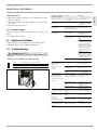
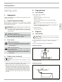
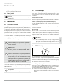
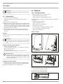
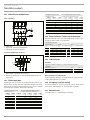
4. Settings
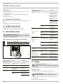
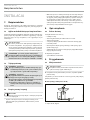
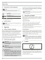
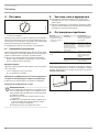
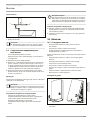
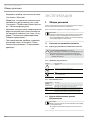
30
60
45
35
40
50
55
°C
D0000041610
Turn the temperature selector to the required position.
If the outlet temperature fails to reach the required level with the
tap fully open and the temperature selector set to maximum, then
more water is flowing through the appliance than can be heated
by the heating element.
Reduce the flow rate at the tap.
4.1 Recommended settings
Your instantaneous water heater offers maximum precision and
maximum convenience in DHW provision. Should you nonetheless
be operating the appliance with a thermostatic valve, we recom-
mend that you:
Set the temperature at the appliance to the maximum tem-
perature. Then set the required set temperature on the ther-
mostatic valve.

OPERATION
Cleaning, care and maintenance
ENGLISH
www.stiebel-eltron.com PEY | 5
Saving energy
The following recommended settings will result in the lowest en-
ergy consumption:
- 38°C for hand washbasins, showers, bath
- 55°C for kitchen sinks
Recommended setting for operation with a thermostatic valve
and water preheated by solar energy
Set the temperature at the appliance to the maximum
temperature.
Following an interruption to the water supply
!
Material losses
To ensure that the bare wire heating system is not dam-
aged following an interruption to the water supply, the
appliance must be restarted by taking the following steps.
Disconnect the appliance from the power supply by
removing the fuses/tripping the MCBs.
Open the tap for one minute until the appliance and
its upstream cold water inlet line are free of air.
Switch the mains power back on again.
5. Cleaning, care and maintenance
Never use abrasive or corrosive cleaning agents. A damp
cloth is sufficient for cleaning the appliance.
Check the taps regularly. Limescale deposits at the tap out-
lets can be removed using commercially available descaling
agents.
6. Troubleshooting
Problem Cause Remedy
The appliance will not
start despite the DHW
valve being fully open.
There is no power.
Check the fuses/MCBs in
your fuse box/distribu-
tion board.
The flow rate is too low.
The aerator in the tap
or the shower head is
scaled up or dirty.
Clean and/or descale the
aerator or shower head.
Required temperature
>45°C is not achieved.
The water supply has
been interrupted.
Vent the appliance and
the cold water inlet line
(see chapter "Settings").
The cold water inlet tem-
perature is >45°C.
Reduce the cold water
inlet temperature.
If you cannot remedy the fault, notify your qualified contractor.
To facilitate and speed up your enquiry, please provide the serial
number from the type plate (000000-0000-00000):
Nr.: 000000-0000-00000
D0000041614

INSTALLATION
Safety
6 | PEY www.stiebel-eltron.com
INSTALLATION
7. Safety
Only a qualified contractor should carry out installation, commis-
sioning, maintenance and repair of the appliance.
7.1 General safety instructions
We guarantee trouble-free function and operational reliability only
if original accessories and spare parts intended for the appliance
are used.
!
Material losses
Observe the maximum inlet temperature. Higher tem-
peratures may damage the appliance. You can limit the
maximum inlet temperature by installing a central ther-
mostatic valve.
WARNING Electrocution
This appliance contains capacitors which are discharged
when disconnected from the power supply. The capacitor
discharge voltage may briefly reach >60VDC.
7.2 Shower operation
CAUTION Burns
If supplying a shower, set the internal temperature
limit to "Tred"; see chapter "Installation alterna-
tives/ Temperature limit".
CAUTION Burns
If the water supplied to the appliance is preheated,
please note the following:
The internally adjustable temperature limit may be ex-
ceeded.
Limit the temperature with an upstream central
thermostatic valve.
7.3 Instructions, standards and regulations
Note
Observe all applicable national and regional regulations
and instructions.
- The IP 25 (hoseproof) rating can only be ensured with a cor-
rectly fitted cable grommet.
- The specific electrical resistivity of the water must not fall
below that stated on the type plate. In a linked water net-
work, observe the lowest electrical water resistivity (see
chapter "Specification/ Application areas/ Conversion
table"). Your water supply utility will advise you of the specif-
ic electrical water resistivity or conductivity.
8. Appliance description
8.1 Standard delivery
The following are delivered with the appliance:
- Wall mounting bracket
- Threaded stud for wall mounting
- Installation template
- 2 twin connectors (cold water with shut-off valve)
- Flat gaskets
- Cable grommet (power cable from above/ below)
- Screws/ rawl plugs for securing the back panel to allow for
water connection on finished walls
For appliance replacement:
- 2 tap extensions
9. Preparation
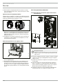
9.1 Installation location
!
Material losses
Install the appliance in a room free from the risk of frost.
Always install the appliance vertically and near the draw-off
point.
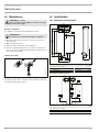
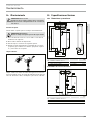
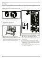
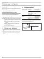
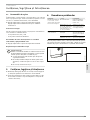
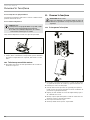
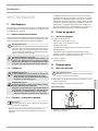
The appliance is suitable for undersink and oversink installation.
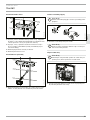
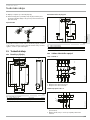
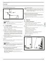
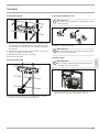
Undersink installation
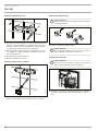
26�02�02�1345
1
2
1 Cold water inlet
2 DHW outlet
Oversink installation
12
26�02�02�1344
1 Cold water inlet
2 DHW outlet

INSTALLATION
Installation
ENGLISH
www.stiebel-eltron.com PEY | 7
Note
Mount the appliance on the wall. The wall must have
sufficient load bearing capacity.
9.2 Water installation
- No safety valve is required.
- Safety valves are not permissible in the DHW pipe.
Flush the water line thoroughly.
Ensure that the flow rate for switching on the appliance is
achieved (see chapter "Specification/ Data table", On). If the
flow rate is not achieved, remove the flow limiter (see chap-
ter "Installation/ Removing the flow limiter").
Increase the mains water pressure if the required flow rate is
not achieved with the draw-off valve fully opened.
Taps
Use appropriate pressure taps. Open vented taps are not per-
missible.
Note
Never use the shut-off valve in the cold water inlet to
reduce the flow rate. It is intended for shutting off the
appliance.
Permissible water line materials
- Cold water inlet pipe:
Pipes made from galvanised steel, stainless steel, copper or
plastic
- DHW outlet line:
Pipes made from stainless steel, copper or plastic
!
Material losses
If plastic pipework systems are used, take into account
the maximum inlet temperature and the maximum pres-
sure (see chapter "Specification/ Data table").
Flexible water connection lines
If the appliance is installed with flexible water connection
lines, ensure that the pipe bends with bayonet fittings do not
become twisted inside the appliance.
Secure the back panel at the bottom with two additional
screws.
10. Installation
10.1 Standard installation
- Electrical connection from above; installation on unfinished
walls
- Water connection on unfinished walls
- Medium connected load is selected
For further installation options, see chapter "Alternative instal-
lation methods":
- Electrical connection from below on unfinished walls
- Electrical connection on finished walls
- Connecting a load shedding relay
- Water installation on finished walls
- Water connection on unfinished walls for appliance
replacement
- Operation with preheated water
- Temperature limit
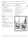
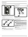
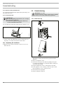
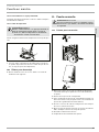
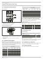
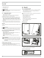
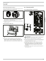
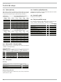
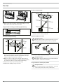
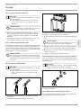
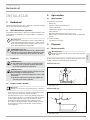
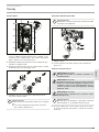
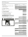
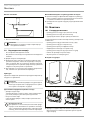
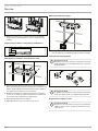
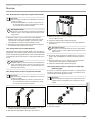
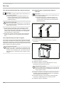
Opening the appliance
D0000041615
Open the appliance by releasing the snap lock.
NT
T-
so
X1
26�02�02�0762
Remove the back panel by pressing the two locking tabs and
pulling the lower section of the back panel forwards.

INSTALLATION
Installation
8 | PEY www.stiebel-eltron.com
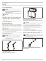
Preparing the power cable
160
≥ 30
26�02�02�0887
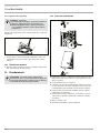
Fitting the wall mounting bracket
26�02�02�0972
Mark out the holes for drilling using the installation tem-
plate. If the appliance is to be installed with water connec-
tions on finished walls, also mark out the fixing holes in the
lower part of the template.
Drill the holes and secure the wall mounting bracket with
2screws and 2rawl plugs (screws and rawl plugs are not
part of the standard delivery).
Fit the threaded stud provided.
Fit the wall mounting bracket.
Fitting the cable grommet
26�02�02�0950
Fit the cable grommet. For connecting cables >6mm², en-
large the hole in the cable grommet.
Making the water connection
!
Material losses
Carry out all water connection and installation work in
accordance with regulations.
26�02�02�0948
Seal and insert the twin connectors.
!
Material losses
Never use the shut-off valve in the cold water inlet to
reduce the flow rate.
Preparing the back panel
!
Material losses
If you break open the wrong knock-out in the back panel
by mistake, you must use a new back panel.
L
L
L
D0000041893
Break out the cable grommet knock-out in the back panel.
Deburr any sharp edges with a file if necessary.

INSTALLATION
Installation
ENGLISH
www.stiebel-eltron.com PEY | 9
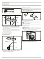
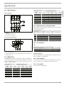
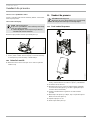
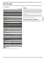
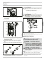
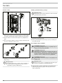
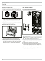
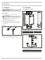
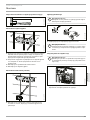
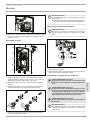
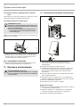
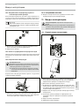
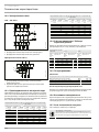
Installing the appliance
L
L
L
3
L3’
4
L2’
1
L1’
2
L
L
L
MV
NT C
T- soll
X1 1
D0000041894
Push the back panel over the threaded stud and the cable
grommet. Pull the cable grommet by the locking hooks into
the back panel using pliers, until both locking hooks audibly
click into place.
Remove the protective transport plugs from the water
connections.
Press the back panel firmly into place and lock the fixing tog-
gle by turning it clockwise through 90°.
D0000041925
Screw the water connection pipes with flat gaskets onto the
twin connectors.
!
Material losses
The strainer must be fitted for the appliance to function.
When replacing an appliance, check whether the
strainer is installed (see chapter "Maintenance").
Removing the flow limiter
!
Material losses
If you use a thermostatic valve, the flow limiter must not
be removed.
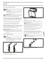
L1’
2
L
L
L
X11
26�02�02�0771
2
1
1 Plastic profile washer
2 Flow limiter
Remove the flow limiter and refit the plastic profile washer.
Making the electrical connection
WARNING Electrocution
Carry out all electrical connection and installation work
in accordance with relevant regulations.
WARNING Electrocution
The connection to the power supply must be in the form
of a permanent connection in conjunction with the re-
movable cable grommet. Ensure the appliance can be
separated from the power supply by an isolator that dis-
connects all poles with at least 3mm contact separation.
WARNING Electrocution
Ensure that the appliance is earthed.
!
Material losses
Observe the type plate. The specified voltage must match
the mains voltage.
Connect the power cable to the mains terminal (see chapter
"Specification/ Wiring diagram").

INSTALLATION
Installation
10 | PEY www.stiebel-eltron.com
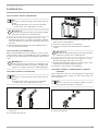
Re-plugging the coding card
In its delivered condition, the appliance is set to 21kW. When
changing to a different connected load, carry out the following
steps:
26�02�02�0822
Re-plug the coding card according to the selected connected
load (for selectable connected load and fuse protection of the
appliance, see "Specification/ Data table").
Tick the selected connected load on the type plate. Use a
ballpoint pen to do this.
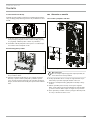
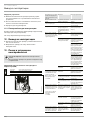
Fitting the base part of the back panel
3
L
3’
4
L
2’
1
L
1’
2
L
L
L
NT C
T- sol
l
X11
26�02�02�1348
Position the lower back panel on the main back panel and
click it into place.
Align the mounted appliance by undoing the fixing toggle,
aligning the power supply and back panel, and then re-tight-
ening the fixing toggle. If the back panel is not flush with the
wall, the appliance can be secured at the bottom with two
additional screws.
10.2 Alternative installation methods
10.2.1 Electrical connection from below on unfinished walls
1
L1í
2
L
L
L
X11
26�02�02�0767
Fit the cable grommet.
!
Material losses
If you break open the wrong knock-out in the back panel
by mistake, you must use a new back panel.
Break out the cable grommet knock-out in the back panel.
Deburr any sharp edges with a file if necessary.
Reposition the mains terminal in the appliance from the top
to the bottom.
Push the back panel over the threaded stud and the cable
grommet. Pull the cable grommet by the locking hooks into
the back panel using pliers, until both locking hooks audibly
click into place.
Press the back panel firmly into place and lock the fixing tog-
gle by turning it clockwise through 90°.

INSTALLATION
Installation
ENGLISH
www.stiebel-eltron.com PEY | 11
10.2.2 Electrical connection on finished walls
Note
This type of connection changes the IP rating of the ap-
pliance.
Change the type plate. Cross out "IP 25" and mark
the box "IP 24". Use a ballpoint pen to do this.
!
Material losses
If you break open the wrong knock-out in the back panel
by mistake, you must use a new back panel.
Cleanly cut or break out the required cable entries in the
back panel (for positions, see chapter "Specification/ Dimen-
sions and connections"). Deburr any sharp edges with a file if
necessary.
Route the power cable through the cable grommet and con-
nect it to the mains terminal.
10.2.3 Connecting a load shedding relay
When operating additional electric appliances, such as electric
storage heaters, install a load shedding relay in the distribution
board. The relay responds when the instantaneous water heater
starts.
!
Material losses
Connect the phase that switches the load shedding relay
to the indicated terminal of the mains terminal in the
appliance (see chapter "Specification/ Wiring diagram").
10.2.4 Water installation on finished walls
Note
This type of connection changes the IP rating of the ap-
pliance.
Change the type plate. Cross out "IP 25" and mark
the box "IP 24". Use a ballpoint pen to do this.
26�02�02�0765
Fit water plugs with gaskets to seal the concealed
connections.
Fit a suitable pressure tap.
26�02�02�1006
Click the lower section of the back panel into place in the
upper section of the back panel.
Secure the connection pipes to the appliance.
Secure the back panel at the bottom with two additional
screws.
!
Material losses
If you break open the wrong knock-out in the back panel
by mistake, you must use a new back panel.
Cleanly break out the knock-outs in the appliance cover. De-
burr any sharp edges with a file if necessary.
Slide the lower back panel under the connection pipes of the
tap and click the lower back panel into place.
Secure the connection pipes to the appliance.
10.2.5 Water installation on unfinished walls for appliance
replacement
If the existing twin connectors of the old appliance only protrude
from the wall by approx.16mm, you cannot use the twin con-
nectors provided.
Note
With this connection, the cold water supply can only be
shut off within the domestic installation.
16
D0000041634
Seal and fit the screw-in tap extensions provided.
Connect the appliance.

INSTALLATION
Commissioning
12 | PEY www.stiebel-eltron.com
10.2.6 Operation with preheated water
You can limit the maximum inlet temperature by installing a cen-
tral thermostatic valve.
10.2.7 Temperature limit
CAUTION Burns
When operating with preheated water, the set temper-
ature limit may be ineffective.
In such cases, limit the temperature with an up-
stream central thermostatic valve.
You can adjust the temperature limit inside the appliance cover.
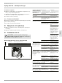
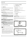
Tred
Tmax
D0000046203
2
1
1 Position "Tred" (55°C): Temperature limit
2 Position "Tmax": No temperature limit, for temperature set-
ting range, see chapter "Specification/Data table".
10.3 Completing the installation
Open the shut-off valve in the twin connector or the cold
water inlet line.
11. Commissioning
WARNING Electrocution
Commissioning must only be carried out by a qualified
contractor in accordance with safety regulations.
11.1 Initial start-up
L
L
3
L
3’
4
L
2
’
1
L
1
’
2
MV
NT C
T- soll
18
2
1
24
k W
D0000041613
Open and close all connected draw-off valves several times,
until all air has been purged from the pipework and the
appliance.
Carry out a tightness check.
Activate the safety pressure limiter by firmly pressing the
reset button (the appliance is delivered with the safety pres-
sure limiter deactivated).
Plug the temperature selector cable plug into the PCB.
Fit the appliance cover, ensuring it clicks into place. Check
that the appliance cover is seated correctly.
Switch the power supply ON.
Check the appliance function.

INSTALLATION
Appliance shutdown
ENGLISH
www.stiebel-eltron.com PEY | 13
Appliance handover
Explain the appliance function to users and familiarise them
with how it works.
Make the user aware of potential dangers, especially the risk
of scalding.
Hand over these instructions.
11.2 Recommissioning
Vent the appliance and the cold water inlet line (see chapter "Set-
tings").
See chapter "Initial start-up".
12. Appliance shutdown
Isolate all poles of the appliance from the power supply.
Drain the appliance (see chapter "Maintenance").
13. Troubleshooting
WARNING Electrocution
To test the appliance, it must be supplied with power.
Indicator options for diagnostic traffic light (LED)
Red Illuminates in the event of a fault
Yellow Illuminates during heating operation
Green Flashing: Appliance connected to power supply
1
D0000041794
1 Diagnostic traffic light
Fault / LED diagnos-
tic traffic light
Cause Remedy
The flow rate is too low. The strainer in the appli-
ance is dirty.
Clean the strainer.
The set temperature is
not achieved.
One phase down.
Check the fuse/MCB in
your fuse box/distribu-
tion board.
The heating system does
not switch on.
Air has been detected in
the water and heating
output is briefly switched
off.
The appliance restarts
after one minute.
No hot water and no traf-
fic light display.
The MCB/fuse has re-
sponded/blown.
Check the fuse/MCB in
your fuse box/distribu-
tion board.
Safety pressure limiter
AP 3 has tripped.
Remove the cause of the
fault (e.g. faulty pressure
flush).
Protect the heating sys-
tem against overheating
by opening a draw-off
valve downstream of the
appliance for one minute.
This depressurises and
cools down the heating
system.
Activate the safety
pressure limiter at flow
pressure by pressing the
reset button (see chapter
"Commissioning").
The PCB is faulty. Check the PCB and re-
place if required.
Traffic light display:
Green flashing or con-
stantly on
The PCB is faulty.
Check the PCB and re-
place if required.
No hot water at flow
rate of
>3l/min.
The flow meter (DFE) is
not plugged in.
Plug the flow meter plug
back in.
The flow meter (DFE) is
faulty.
Check the flow meter and
replace if required.
Traffic light display:
Steady yellow light,
flashing green light
No hot water at flow rate
>3l/min.
The high limit safety
cut-out has responded or
suffered a lead break.
Check the high limit safe-
ty cut-out and replace it
if required.
The heating system is
faulty.
Check the heating system
resistor and replace if
required.
The PCB is faulty. Check the PCB and re-
place if required.
Traffic light display: Yel-
low constantly on; green
flashing
The outlet sensor is
unplugged or the lead is
broken.
Plug in the outlet sensor
or replace if required.
Traffic light display: Red
constantly on; green
flashing
The cold water sensor is
faulty.
Check the PCB and re-
place if required.
No hot water
Required temperature
>45°C is not achieved.
The cold water inlet tem-
perature exceeds 45°C.
Reduce the cold water
inlet temperature to the
appliance.
Traffic light display: Red
constantly on; green
flashing
The outlet sensor is
faulty (short circuit).
Check the outlet sensor
and replace if required.

INSTALLATION
Maintenance
14 | PEY www.stiebel-eltron.com
14. Maintenance
WARNING Electrocution
Before any work on the appliance, disconnect all poles
from the power supply.
Draining the appliance
The appliance can be drained for maintenance work.
WARNING Burns
Hot water may escape when draining the appliance.
Close the shut-off valve in the twin connector or the cold
water inlet line.
Open all draw-off valves.
Undo the water connections on the appliance.
Store the dismantled appliance in a room free from the risk
of frost, as water residues remaining inside the appliance can
freeze and cause damage.
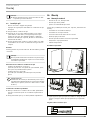
Cleaning the strainer
26�02�02�0949
If dirty, clean the strainer in the threaded cold water fitting. Close
the shut-off valve in the cold water inlet line before removing,
cleaning and refitting the strainer.
15. Specification
15.1 Dimensions and connections
395
100
485
325
45
5
93
226
190
50
112
190
35
c01
c06
b02
D0000017757
PEY
b02 Entry electrical cables I
c01 Cold water inlet Male thread G 1/2 A
c06 DHW outlet Male thread G 1/2 A
Alternative connection options
325
50
50
35
40
b03
b02
b04
b04
b04
D0000019778
PEY
b02 Entry electrical cables I
b03 Entry electrical cables II
b04 Entry electrical cables III

INSTALLATION
ENGLISH
www.stiebel-eltron.com PEY | 15
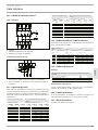
15.2 Wiring diagram
3/PE ~ 380-415 V
85�02�02�0005
1 Heating
2 High limit safety cut-out
3 Safety pressure limiter
Priority control with LR 1-A
85�02�02�0003�
2
1
1 Control cable to the contactor of the 2nd appliance (e.g. elec-
tric storage heater).
2 Control contact drops out when switching the instantaneous
water heater on.
15.3 DHW output
The DHW output is subject to the mains voltage, the appliance's
connected load and the cold water inlet temperature. The rated
voltage and rated output can be found on the type plate (see
chapter "Troubleshooting").
Connected load in kW 38 °C DHW output in l/min.
Rated voltage Cold water inlet temperature
380 V
16.2 7.0 8.3 10.1 12.9
19 8.2 9.7 11.8 15.1
21.7 9.4 11.1 13.5 17.2
18 7.8 9.2 11.2 14.3
21 9.1 10.7 13.0 16.7
24 10.4 12.2 14.9 19.0
19.4 8.4 9.9 12.0 15.4
22.6 9.8 11.5 14.0 17.9
25.8 11.2 13.2 16.0 20.5
Connected load in kW
Rated voltage Cold water inlet temperature
380 V
16.2 5.1 5.8 6.6 7.7
19 6.0 6.8 7.8 9.0
21.7 6.9 7.8 8.9 10.3
18 5.7 6.4 7.3 8.6
21 6.7 7.5 8.6 10.0
24 7.6 8.6 9.8 11.4
19.4 6.2 6.9 7.9 9.2
22.6 7.2 8.1 9.2 10.8
25.8 8.2 9.2 10.5 12.3
15.4 Application areas/ Conversion table
Specific electrical resistivity and specific electrical conductivity
(see chapter "Data table").
Standard specifica-
Resis-
tivity
ρ ≥
Conductivity σ ≤
Resis-
tivity
ρ ≥
Conductivity σ ≤
Resis-
tivity
ρ ≥
Conductivity σ ≤
Ωcm mS/m μS/cm Ωcm mS/m μS/cm Ωcm mS/m μS/cm
900 111 1111 800 125 1250 735 136 1361
1000 100 1000 890 112 1124 815 123 1227
1200 83 833 1070 93 935 985 102 1015
1300 77 769 1175 85 851 1072 93 933
15.5 Pressure drop
Taps
Tap pressure drop at a flow rate of 10 l/min
Mono lever mixer tap, approx. MPa 0.04 - 0.08
Thermostatic valve, approx. MPa 0.03 - 0.05
Hand shower, approx. MPa 0.03 - 0.15
Sizing the pipework
When calculating the size of the pipework, an appliance pressure
drop of 0.1MPa is recommended.
15.6 Fault conditions
In the event of a fault, loads up to a maximum of 95°C at a pres-
sure of 1.2MPa can occur temporarily in the installation.
15.7 Test symbols
See type plate on the appliance.

16 | PEY www.stiebel-eltron.com
INSTALLATION | GUARANTEE | ENVIRONMENT AND RECYCLING
15.8 Energy consumption data
Product datasheet: Conventional water heaters to regulation (EU)
no. 812/2013 and 814/2013
PEY 18/21/24
233993
Manufacturer STIEBEL ELTRON
Load profile S
Energy efficiency class A
Energy conversion efficiency % 39
Annual power consumption kWh 477
Default temperature setting °C 60
Sound power level dB(A) 15
Special information on measuring efficiency Data at Pmax.
Daily power consumption kWh 2,198
15.9 Data table
PEY 18/21/24
233993
Electrical data
Rated voltage V 380 400 415
Rated output kW 16.2/19/21.7 18/21/24 19.4/22.6/25.8
Rated current A 27.6/29.5/33.3 29/31/35 30.1/32.2/36.3
Fuse protection A 32/32/35 32/32/35 32/32/40
Frequency Hz 50/60 50/60 50/-
Phases 3/PE
Specific resistance ρ
15
≥ (at ϑcold
≤25°C)
Ω cm 900 900 1000
Specific conductivity σ
15
≤ (at
ϑcold ≤25 °C)
μS/cm 1111 1111 1000
Specific resistance ρ
15
≥ (at ϑcold
≤45°C)
Ω cm 1200 1200 1300
Specific conductivity σ
15
≤ (at
ϑcold ≤45°C)
μS/cm 833 833 770
Max. mains impedance at 50Hz Ω 0.284 0.270 0.260
Versions
Heating system heat generator Bare wire
Insulating block Plastic
Adjustable connected load X
Temperature settings °C Approx. 30-60
Cover and back panel Plastic
IP rating IP25
Colour White
Connections
Water connection G 1/2 A
Application limits
Max. permissible pressure MPa 1
Max. inlet temperature for re-
heating
°C 45
Values
Max. permissible inlet temper-
ature
°C 60
ON l/min >3
Flow rate for pressure drop l/min 5.2/6.0/6.9
Pressure drop at flow rate MPa 0.08/0.10/0.13 (0.06/0.08/0.10 without
DMB)
Flow rate limit at l/min 8.0
DHW delivery l/min 9.4/11.0/12.6
Δϑ on delivery K 26
Hydraulic data
Nominal capacity l 0.4
Dimensions
Height mm 485
Width mm 226
Depth mm 93
PEY 18/21/24
Weights
Weight kg 3.6
Note
The appliance conforms to IEC 61000-3-12.
Guarantee
The guarantee conditions of our German companies do not
apply to appliances acquired outside of Germany. In countries
where our subsidiaries sell our products a guarantee can only
be issued by those subsidiaries. Such guarantee is only grant
-
ed if the subsidiary has issued its own terms of guarantee. No
other guarantee will be granted.
We shall not provide any guarantee for appliances acquired in
countries where we have no subsidiary to sell our products.
This will not aect warranties issued by any importers.
Environment and recycling
We would ask you to help protect the environment.
After use,
dispose of the various materials in accordance with national
regulations.
GUARANTEE
ENVIRONMENT AND RECYCLING

ESPA ÑOL
www.stiebel-eltron.com PEY | 17
CONTENIDO | INDICACIONES ESPECIALES
INDICACIONES ESPECIALES
OPERACIÓN
1. Indicaciones generales ������������������������������������ 18
1.1 Instrucciones de seguridad ����������������������������������� 18
1.2 Otras marcas presentes en esta documentación ��������� 19
1.3 Unidades de medida ������������������������������������������� 19
2. Seguridad ��������������������������������������������������� 19
2.1 Utilización conforme a las prescripciones ����������������� 19
2.2 Instrucciones generales de seguridad ���������������������� 19
3. Descripción del aparato ����������������������������������� 19
4. Ajustes ������������������������������������������������������ 20
4.1 Recomendaciones de configuración ������������������������20
5. Limpieza, conservación y mantenimiento ��������������� 20
6. Resolución de problemas ��������������������������������� 20
INSTALACIÓN
7. Seguridad ��������������������������������������������������� 21
7.1 Instrucciones generales de seguridad ���������������������� 21
7.2 Modo de ducha �������������������������������������������������� 21
7.3 Reglamentos, normas y disposiciones ��������������������� 21
8. Descripción del aparato ����������������������������������� 21
8.1 Ámbito de suministro ������������������������������������������ 21
9. Preparativos ������������������������������������������������ 21
9.1 Lugar de montaje ����������������������������������������������� 21
9.2 Instalación de agua �������������������������������������������� 22
10. Montaje ����������������������������������������������������� 22
10.1 Montaje estándar ����������������������������������������������� 22
10.2 Alternativas de montaje ��������������������������������������� 25
10.3 Últimos pasos de montaje ������������������������������������ 27
11. Puesta en marcha ������������������������������������������ 27
11.1 Primera puesta en marcha �����������������������������������27
11.2 Nueva puesta en marcha ��������������������������������������28
12. Puesta fuera de servicio ����������������������������������� 28
13. Localización y reparación de averías �������������������� 28
14. Mantenimiento ��������������������������������������������� 29
15. Especificaciones técnicas ���������������������������������� 29
15.1 Dimensiones y conexiones ������������������������������������ 29
15.2 Esquema de conexiones eléctricas �������������������������� 30
15.3 Rendimiento de agua caliente �������������������������������30
15.4 Ámbitos de aplicación/ Tabla de conversión ������������� 30
15.5 Pérdida de presión ���������������������������������������������30
15.6 Condiciones en caso de avería ������������������������������� 30
15.7 Sello de certificación ������������������������������������������� 30
15.8 Datos sobre el consumo energético ������������������������� 31
15.9 Tabla de especificaciones ������������������������������������� 31
GARANTÍA
MEDIO AMBIENTE Y RECICLADO
INDICACIONES
ESPECIALES
- El aparato puede ser utilizado por niños de a
partir de 3años, así como por personas con
capacidades físicas, sensoriales o mentales
limitadas, o con falta de experiencia y conoci-
mientos, solo bajo la vigilancia de otra perso-
na o si antes han recibido instrucciones sobre
el uso seguro del aparato y han comprendido
los peligros que pueden derivarse. No deje
que los niños jueguen con el aparato. Las ta-
reas de limpieza y mantenimiento propias del
usuario no deben ser realizadas por niños sin
vigilancia.
- Los grifos/válvulas pueden alcanzar tempe-
raturas de hasta 60°C. A temperaturas de
salida superiores a 43°C existe peligro de
escaldamiento.
- El aparato es apto para el abastecimiento de
una ducha (modo de ducha). Si el aparato
se utiliza también o exclusivamente para el
modo de ducha, el profesional técnico es-
pecializado debe activar el rango de ajuste
de temperatura a través de la limitación de
temperatura (Tred = 55°C) en el aparato. Si
se utiliza agua precalentada, asegúrese de
que la temperatura de admisión no supere los
55°C.
- El aparato debe poder desconectarse omni-
polarmente de la red eléctrica mediante una
separación de al menos 3mm.
- La tensión indicada debe coincidir con la ten-
sión de red disponible.
- El aparato debe estar conectado a un conduc-
tor de puesta a tierra.
- El aparato debe estar continuamente conecta-
do a un cableado fijo.
- Fije el aparato tal como se describe en el ca-
pítulo "Instalación/ Montaje".

OPERACIÓN
Indicaciones generales
18 | PEY www.stiebel-eltron.com
- Tenga en cuenta la presión máxima admisible
(véase el capítulo "Instalación/ Especificacio-
nes técnicas/ Tabla de especificaciones").
- La resistencia específica del agua de la red
de abastecimiento de agua no debe tener un
valor inferior al mínimo (véase el capítulo
"Instalación / Especificaciones técnicas / Tabla
de especificaciones").
- Vacíe el aparato tal y como se describe en el
capítulo "Instalación/ Mantenimiento/ Vacia-
do del aparato".
OPERACIÓN
1. Indicaciones generales
Los capítulos "Indicaciones especiales" y "Utilización" están dirigi-
dos al usuario del aparato y al profesional técnico especializado.
El capítulo "Instalación" está dirigido al profesional técnico es-
pecializado.
Nota
Lea atentamente estas instrucciones antes del uso y ar-
chívelas en un lugar seguro.
Si entrega este aparato a otros usuarios, no olvide incluir
las instrucciones.
1.1 Instrucciones de seguridad
1.1.1 Estructura de las instrucciones de seguridad
!
PALABRA DE ADVERTENCIA Tipo de peligro
Mediante este tipo de palabras se explican las posibles
consecuencias en caso de desobedecimiento de las ins-
trucciones de seguridad.
Aquí se proponen las medidas necesarias para evi-
tar el peligro.
1.1.2 Símbolos, tipo de peligro
Símbolo Tipo de peligro
Lesión
Electrocución
Quemaduras
(quemaduras, escaldadura)
1.1.3 Palabras de advertencia
PALABRA DE
ADVERTENCIA
Significado
PELIGRO Indicaciones cuyo desobedecimiento tiene como conse-
cuencia lesiones graves o la muerte.
ADVERTENCIA Indicaciones cuyo desobedecimiento puede tener como
consecuencia lesiones graves o la muerte.
PRECAUCIÓN Indicaciones cuyo desobedecimiento puede tener como
consecuencia lesiones de gravedad media o baja.
!

OPERACIÓN
Seguridad
ESPA ÑOL
www.stiebel-eltron.com PEY | 19
1.2 Otras marcas presentes en esta documentación
Nota
Las indicaciones generales se señalizan mediante el sím-
bolo adyacente.
Lea atentamente las indicaciones.
Símbolo Significado
Daños materiales
(daños en el aparato, indirectos, medioambientales)
Eliminación del aparato
Este símbolo le indica que usted tiene que hacer algo. Se
describen paso a paso las medidas necesarias.
1.3 Unidades de medida
Nota
Si no se indica lo contrario, todas las dimensiones estarán
expresadas en milímetros.
2. Seguridad
2.1 Utilización conforme a las prescripciones
El aparato está previsto para utilizarse en un ámbito doméstico.
Las personas no instruidas lo pueden manejar de forma segura.
El aparato puede utilizarse igualmente en ámbitos que no sean
domésticos, como en pequeñas empresas, siempre que se maneje
del mismo modo.
El aparato a presión sirve para calentar agua potable o para re-
calentar agua previamente calentada. El aparato puede alimentar
uno o varios puntos de dispensado.
Cualquier otro uso distinto al aquí previsto se considera un uso
indebido. Se considera uso previsto el cumplimiento de estas ins-
trucciones, así como las instrucciones de los accesorios utilizados.
2.2 Instrucciones generales de seguridad
PRECAUCIÓN Quemaduras
Los grifos/válvulas pueden alcanzar temperaturas de
hasta 60°C. A temperaturas de salida superiores a 43°C
existe peligro de escaldamiento.
PRECAUCIÓN Quemaduras
La temperatura del agua caliente puede ser distinta de
la temperatura de referencia ajustada en un funciona-
miento con agua precalentada; p. ej., un sistema de ca-
lefacción solar.
!
ADVERTENCIA Lesiones
El aparato puede ser utilizado por niños a partir de 3
años, así como por personas con capacidades físicas,
sensoriales o mentales limitadas, o con falta de expe-
riencia y conocimientos, solo bajo la vigilancia de otra
persona o si antes han recibido instrucciones sobre el
uso seguro del aparato y han comprendido los peligros
que pueden derivarse. No deje que los niños jueguen
con el aparato. Las tareas de limpieza y mantenimiento
propias del usuario no deben ser realizadas por niños
sin vigilancia.
En caso de que niños u otras personas con capacidades físicas,
sensoriales o mentales limitadas utilicen el aparato, recomen-
damos una limitación de temperatura permanente. La limitación
puede realizarla un profesional técnico especializado.
!
Daños materiales
El usuario debe proteger el aparato y los grifos/válvulas
frente a la formación de escarcha.
3. Descripción del aparato
El calentador instantáneo con regulación electrónica con adap-
tación automática de la potencia mantiene constante la tempe-
ratura de salida hasta el límite de rendimiento. Posteriormente,
la temperatura se selecciona mediante la grifería de dispensado.
Temperatura del agua caliente
La temperatura de salida del agua caliente puede regularse me-
diante un sistema de regulación continua.
Limitación de temperatura interna (profesional técnico
especializado)
Si así se desea, el profesional técnico especializado puede activar
una limitación de temperatura permanente.
Cuando se suministra una ducha, el profesional técnico especia-
lizado debe activar la limitación de temperatura.
Sistema de calefacción
El sistema de calefacción de cables desnudos tiene una capa de
plástico estanca a la presión. El sistema de calefacción es apto
para agua tanto pobre como rica en cal, ya que es resistente a
la acumulación de cal. El sistema de calefacción abastece agua
caliente de forma rápida y eficaz.
Nota
El aparato está equipado con un sistema de detección
de aire que evita que se produzcan daños en el sistema
de calefacción. Si durante el funcionamiento entra aire
en el aparato, el aparato desconectará la potencia de
calefacción durante un minuto, con lo que protegerá el
sistema de calefacción.
!

OPERACIÓN
Ajustes
20 | PEY www.stiebel-eltron.com
4. Ajustes
30
60
45
35
40
50
55
°C
D0000041610
Gire el selector de temperatura hacia la posición deseada.
Si con el grifo totalmente abierto y el ajuste de temperatura máxi-
mo no se alcanza una temperatura de salida suficiente, fluirá un
caudal de agua a través del aparato mayor que el que el cuerpo
calefactor es capaz de calentar.
Reduzca el caudal del grifo.
4.1 Recomendaciones de configuración
Su calentador instantáneo asegura la máxima precisión y el máxi-
mo confort en la preparación de agua caliente. Si a pesar de ello
utiliza el aparato con una valvulería de termostato, le recomen-
damos que:
Configure la temperatura del aparato a la temperatura máxi-
ma. Ajuste la temperatura de referencia deseada en la valvu-
lería del termostato.
Ahorrar energía
Se consumirá menos energía con los siguientes ajustes recomen-
dados:
- 38°C para el lavamanos, ducha y bañera
- 55°C para el fregadero de la cocina
Ajustes recomendados para el funcionamiento con una
valvulería de termostato y agua precalentada por energía solar
Configure la temperatura del aparato a la temperatura
máxima.
Tras interrumpir el abastecimiento de agua
!
Daños materiales
Para que el sistema de calefacción de cables desnudos no
se destruya tras interrumpir el abastecimiento de agua,
el aparato se tiene que volver a poner en marcha con los
pasos siguientes.
Desenergice el aparato desconectando los fusibles.
Abra el grifo durante un minuto hasta que no quede
aire en el aparato ni en la tubería de suministro de
agua fría conectada antes.
Vuelva a encender la alimentación eléctrica.
5. Limpieza, conservación y
mantenimiento
No utilice detergentes agresivos ni disolventes. Para conser-
var y limpiar el aparato basta con utilizar un paño húmedo.
Revise la grifería/valvulería periódicamente. La cal en las
tomas de grifos puede eliminarse utilizando los productos
antical disponibles en el mercado.
6. Resolución de problemas
Problema Causa Solución
El aparato no se enciende
a pesar de que la válvula
de agua caliente está
completamente abierta.
No hay tensión.
Revise los fusibles de la
caja de fusibles domés-
tica.
Caudal insuficiente. El
regulador de chorro en
el grifo o el cabezal de
la ducha presentan cal o
están sucios.
Limpie y/o elimine la cal
del regulador de chorro o
del cabezal de la ducha.
No se alcanza la tempe-
ratura deseada > 45°C.
El abastecimiento de
agua está interrumpido.
Purgue el aire del
aparato y del tubo de
alimentación de agua
fría (consulte el capítulo
"Configuración").
La temperatura de ad-
misión del agua fría es
> 45°C.
Reduzca la temperatura
de admisión del agua
fría.
Si no puede solucionar la causa, llame al profesional técnico espe-
cializado. Para poder ayudarle mejor y con mayor rapidez, indique
el número de la placa de especificaciones técnicas (000000-0000-
00000):
Nr.: 000000-0000-00000
D0000041614
Strona się ładuje...
Strona się ładuje...
Strona się ładuje...
Strona się ładuje...
Strona się ładuje...
Strona się ładuje...
Strona się ładuje...
Strona się ładuje...
Strona się ładuje...
Strona się ładuje...
Strona się ładuje...
Strona się ładuje...
Strona się ładuje...
Strona się ładuje...
Strona się ładuje...
Strona się ładuje...
Strona się ładuje...
Strona się ładuje...
Strona się ładuje...
Strona się ładuje...
Strona się ładuje...
Strona się ładuje...
Strona się ładuje...
Strona się ładuje...
Strona się ładuje...
Strona się ładuje...
Strona się ładuje...
Strona się ładuje...
Strona się ładuje...
Strona się ładuje...
Strona się ładuje...
Strona się ładuje...
Strona się ładuje...
Strona się ładuje...
Strona się ładuje...
Strona się ładuje...
Strona się ładuje...
Strona się ładuje...
Strona się ładuje...
Strona się ładuje...
Strona się ładuje...
Strona się ładuje...
Strona się ładuje...
Strona się ładuje...
Strona się ładuje...
Strona się ładuje...
Strona się ładuje...
Strona się ładuje...
Strona się ładuje...
Strona się ładuje...
Strona się ładuje...
Strona się ładuje...
Strona się ładuje...
Strona się ładuje...
Strona się ładuje...
Strona się ładuje...
Strona się ładuje...
Strona się ładuje...
Strona się ładuje...
Strona się ładuje...
Strona się ładuje...
Strona się ładuje...
Strona się ładuje...
Strona się ładuje...
Strona się ładuje...
Strona się ładuje...
Strona się ładuje...
Strona się ładuje...
Strona się ładuje...
Strona się ładuje...
Strona się ładuje...
Strona się ładuje...
Strona się ładuje...
Strona się ładuje...
Strona się ładuje...
Strona się ładuje...
Strona się ładuje...
Strona się ładuje...
Strona się ładuje...
Strona się ładuje...
Strona się ładuje...
Strona się ładuje...
Strona się ładuje...
Strona się ładuje...
Strona się ładuje...
Strona się ładuje...
Strona się ładuje...
Strona się ładuje...
Strona się ładuje...
Strona się ładuje...
Strona się ładuje...
Strona się ładuje...
Strona się ładuje...
Strona się ładuje...
Strona się ładuje...
Strona się ładuje...
Strona się ładuje...
Strona się ładuje...
Strona się ładuje...
Strona się ładuje...
Strona się ładuje...
Strona się ładuje...
Strona się ładuje...
Strona się ładuje...
Strona się ładuje...
Strona się ładuje...
Strona się ładuje...
Strona się ładuje...
Strona się ładuje...
Strona się ładuje...
Strona się ładuje...
Strona się ładuje...
Strona się ładuje...
Strona się ładuje...
Strona się ładuje...
Strona się ładuje...
-
 1
1
-
 2
2
-
 3
3
-
 4
4
-
 5
5
-
 6
6
-
 7
7
-
 8
8
-
 9
9
-
 10
10
-
 11
11
-
 12
12
-
 13
13
-
 14
14
-
 15
15
-
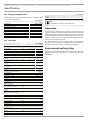 16
16
-
 17
17
-
 18
18
-
 19
19
-
 20
20
-
 21
21
-
 22
22
-
 23
23
-
 24
24
-
 25
25
-
 26
26
-
 27
27
-
 28
28
-
 29
29
-
 30
30
-
 31
31
-
 32
32
-
 33
33
-
 34
34
-
 35
35
-
 36
36
-
 37
37
-
 38
38
-
 39
39
-
 40
40
-
 41
41
-
 42
42
-
 43
43
-
 44
44
-
 45
45
-
 46
46
-
 47
47
-
 48
48
-
 49
49
-
 50
50
-
 51
51
-
 52
52
-
 53
53
-
 54
54
-
 55
55
-
 56
56
-
 57
57
-
 58
58
-
 59
59
-
 60
60
-
 61
61
-
 62
62
-
 63
63
-
 64
64
-
 65
65
-
 66
66
-
 67
67
-
 68
68
-
 69
69
-
 70
70
-
 71
71
-
 72
72
-
 73
73
-
 74
74
-
 75
75
-
 76
76
-
 77
77
-
 78
78
-
 79
79
-
 80
80
-
 81
81
-
 82
82
-
 83
83
-
 84
84
-
 85
85
-
 86
86
-
 87
87
-
 88
88
-
 89
89
-
 90
90
-
 91
91
-
 92
92
-
 93
93
-
 94
94
-
 95
95
-
 96
96
-
 97
97
-
 98
98
-
 99
99
-
 100
100
-
 101
101
-
 102
102
-
 103
103
-
 104
104
-
 105
105
-
 106
106
-
 107
107
-
 108
108
-
 109
109
-
 110
110
-
 111
111
-
 112
112
-
 113
113
-
 114
114
-
 115
115
-
 116
116
-
 117
117
-
 118
118
-
 119
119
-
 120
120
-
 121
121
-
 122
122
-
 123
123
-
 124
124
-
 125
125
-
 126
126
-
 127
127
-
 128
128
-
 129
129
-
 130
130
-
 131
131
-
 132
132
-
 133
133
-
 134
134
-
 135
135
-
 136
136


STIEBEL ELTRON PEY Operation Instruction
- Typ
- Operation Instruction
w innych językach
- română: STIEBEL ELTRON PEY
Powiązane artykuły
-
STIEBEL ELTRON PEG 13-24 Operation Instruction
-
-
-
-
-
-
-
-
-

