STIEBEL ELTRON PEG 13-24 Operation Instruction
- Typ
- Operation Instruction

OPERATION AND INSTALLATION
OPERACIÓN E INSTALACIÓN
OBSLUHA A INSTALACE
OBSLUHA A INŠTALÁCIA
OBSŁUGA I INSTALACJA
ОБСЛУЖВАНЕ И ИНСТАЛИРАНЕ
Electronically controlled instantaneous water heater | Calentador instantáneo
electrónico | Elektronicky řízený průtokový ohřívač | Elektronicky riadený
prietokový ohrievač | Elektronicznie sterowany przepływowy ogrzewacz wody |
Електронно контролиран проточен бойлер
» PEG 13
» PEG 18
» PEG 21
» PEG 24
Made in Germany

2 | PEG 13-24 www.stiebel-eltron.com
CONTENTS | SPECIAL INFORMATION
SPECIAL INFORMATION
- The appliance may be used by children aged 3
and up and persons with reduced physical, sen-
sory or mental capabilities or a lack of experience
and know-how, provided that they are supervised
or they have been instructed on how to use the
appliance safely and have understood the result-
ing risks. Children must never play with the ap-
pliance. Children must never clean the appliance
or perform user maintenance unless they are
supervised.
- The tap can reach temperatures in excess of
60°C. There is a risk of scalding at outlet temper-
atures in excess of 43 °C.
- Ensure the appliance can be separated from the
power supply by an isolator that disconnects all
poles with at least 3mm contact separation.
- The specified voltage must match the mains
voltage.
- Connect the appliance to earth.
- Connect the appliance permanently to fixed
wiring.
- Secure the appliance as described in chapter "In-
stallation/ Installation".
- Observe the maximum permissible pressure (see
chapter "Specification/ Data table").
- The specific water resistivity of the mains water
supply must not be undershot (see chapter “In-
stallation / Specification / Data table”).
- Drain the appliance as described in chapter "In-
stallation/ Maintenance/ Draining the appliance".
SPECIAL INFORMATION
OPERATION
1. General information �����������������������������������������3
1.1 Safety instructions ����������������������������������������������� 3
1.2 Other symbols in this documentation ����������������������� 3
1.3 Units of measurement ������������������������������������������ 3
2. Safety ���������������������������������������������������������� 3
2.1 Intended use ������������������������������������������������������ 3
2.2 General safety instructions ������������������������������������ 3
2.3 Test symbols ������������������������������������������������������ 4
3. Appliance description ���������������������������������������4
4. Settings �������������������������������������������������������4
5. Cleaning, care and maintenance ���������������������������4
6. Troubleshooting ����������������������������������������������4
INSTALLATION
7. Safety ���������������������������������������������������������� 5
7.1 General safety instructions ������������������������������������ 5
7.2 Instructions, standards and regulations �������������������� 5
8. Appliance description ���������������������������������������5
8.1 Standard delivery ������������������������������������������������ 5
9. Preparations ��������������������������������������������������5
9.1 Installation site ��������������������������������������������������� 5
9.2 Water installation ������������������������������������������������ 6
10. Installation ����������������������������������������������������6
10.1 Standard installation �������������������������������������������� 6
10.2 Alternative installation options ������������������������������� 9
10.3 Completing the installation ����������������������������������� 10
11. Commissioning ��������������������������������������������� 10
11.1 Initial start-up ��������������������������������������������������� 10
11.2 Recommissioning ����������������������������������������������� 11
12. Shutdown ��������������������������������������������������� 11
13. Troubleshooting �������������������������������������������� 12
14. Maintenance ������������������������������������������������ 12
15. Specification ������������������������������������������������ 13
15.1 Dimensions and connections ��������������������������������� 13
15.2 Wiring diagram ������������������������������������������������� 13
15.3 DHW output ������������������������������������������������������ 13
15.4 Application areas/ conversion table ����������������������� 14
15.5 Pressure drop ��������������������������������������������������� 14
15.6 Fault conditions ������������������������������������������������� 14
15.7 Details on energy consumption ������������������������������ 14
15.8 Data table �������������������������������������������������������� 14
GUARANTEE
ENVIRONMENT AND RECYCLING

OPERATION
General information
ENGLISH
www.stiebel-eltron.com PEG 13-24 | 3
OPERATION
1. General information
The chapters "Special Information" and "Operation" are intended
for both the user and qualified contractors.
The chapter "Installation" is intended for qualified contractors.
Note
Read these instructions carefully before using the appli-
ance and retain them for future reference.
Pass on the instructions to any new user where appro-
priate.
1.1 Safety instructions
1.1.1 Structure of safety instructions
!
KEYWORD Type of risk
Here, possible consequences are listed that may result
from failure to observe the safety instructions.
Steps to prevent the risk are listed.
1.1.2 Symbols, type of risk
Symbol Type of risk
Injury
Electrocution
Burns
(burns, scalding)
1.1.3 Keywords
KEYWORD Meaning
DANGER Failure to observe this information will result in serious
injury or death.
WARNING Failure to observe this information may result in serious
injury or death.
CAUTION Failure to observe this information may result in non-seri-
ous or minor injury.
1.2 Other symbols in this documentation
Note
General information is identified by the adjacent symbol.
Read these texts carefully.
Symbol Meaning
Material losses
(appliance damage, consequential losses and environmen-
tal pollution)
Appliance disposal
This symbol indicates that you have to do something. The ac-
tion you need to take is described step by step.
1.3 Units of measurement
Note
All measurements are given in mm unless stated oth-
erwise.
2. Safety
2.1 Intended use
This appliance is intended for domestic use. It can be used safely
by untrained persons. The appliance can also be used in a non-do-
mestic environment, e.g.in a small business, as long as it is used
in the same way.
This pressure appliance is designed to heat DHW. The appliance
can supply one or more draw-off points.
Any other use beyond that described shall be deemed inappropri-
ate. Observation of these instructions and of instructions for any
accessories used is also part of the correct use of this appliance.
2.2 General safety instructions
CAUTION Burns
During operation, the tap can reach temperatures in ex-
cess of 60 °C.
There is a risk of scalding at outlet temperatures in ex-
cess of 43 °C.
!
WARNING Injury
The appliance may be used by children aged3 and up and
persons with reduced physical, sensory or mental capa-
bilities or a lack of experience and know-how, provided
that they are supervised or they have been instructed on
how to use the appliance safely and have understood
the resulting risks. Children must never play with the
appliance. Children must never clean the appliance or
perform user maintenance unless they are supervised.
!
Material losses
The user should protect the appliance and its tap against
frost.
!
!

OPERATION
Appliance description
4 | PEG 13-24 www.stiebel-eltron.com
2.3 Test symbols
See type plate on the appliance.
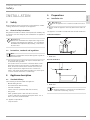
3. Appliance description
You can adjust the DHW outlet temperature via the temperature
selector. From a flow rate of approx. 3 l/min and above, the con-
trol unit regulates the correct output, subject to the temperature
setting and cold water temperature.
Heating system
The bare wire heating system has a pressure-tested plastic cas-
ing. The heating system is suitable for hard and soft water areas
and is largely insusceptible to scale build-up. This heating system
ensures rapid and efficient DHW availability.
Note
The appliance is equipped with an air detector that large-
ly prevents damage to the heating system. If, during op-
eration, air is drawn into the appliance, the appliance
shuts down for one minute, thereby protecting the heat-
ing system.
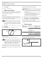
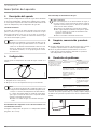
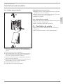
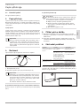
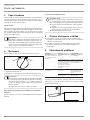
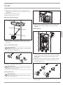
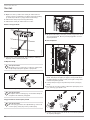
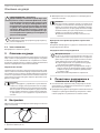
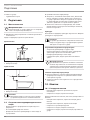
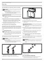
4. Settings
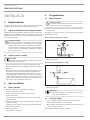
The DHW outlet temperature can be adjusted in 2 stages.
1 2
D0000041611
1 Shower ( 42°C )
2 Kitchen sink ( 55°C )
Click the output selector into the required position.
Note
If the outlet temperature is not sufficiently high when the
draw-off valve is fully open (kitchen sink) and the tem-
perature selector is set to maximum, then more water is
flowing through the appliance than can be heated by the
heating system (appliance is at its output limit).
Reduce the water volume at the draw-off valve.
Recommended setting for operation with a thermostatic valve
Set the temperature at the appliance to the maximum temperature
(kitchen sink).
Following an interruption to the water supply
!
Material losses
Following an interruption of the water supply the appli-
ance must be recommissioned by carrying out the follow-
ing steps, in order to prevent the destruction of the bare
wire heating system.
Disconnect the appliance from the power supply by
removing the fuses/tripping the MCBs.
Open the tap for one minute until the appliance and
its upstream cold water inlet line are free of air.
Switch the mains power back ON again.
5. Cleaning, care and maintenance
Never use abrasive or corrosive cleaning agents. A damp
cloth is sufficient for cleaning the appliance.
Check the taps regularly. Limescale deposits at the tap out-
lets can be removed using commercially available descaling
agents.
6. Troubleshooting
Problem Cause Remedy
The appliance will not
start despite the DHW
valve being fully open.
There is no power.
Check the fuses/MCBs in
your fuse box/distribu-
tion panel.
The flow rate is too low
for switching on the
heating output. The
aerator in the tap or the
shower head is scaled up
or contaminated.
Clean and/or descale the
aerator or shower head.
Required temperature
>45°C is not achieved.
The water supply has
been interrupted.
Vent the appliance and
the cold water inlet line
(see chapter "Settings").
The cold water inlet tem-
perature is >45°C.
Reduce the cold water
inlet temperature.
If you cannot remedy the fault, notify your qualified contractor.
To facilitate and speed up assistance, please provide the numbers
from the type plate (000000-0000-00000):
Nr.: 000000-0000-00000
D0000041614

ENGLISH
www.stiebel-eltron.com PEG 13-24 | 5
INSTALLATION
Safety
INSTALLATION
7. Safety
Only a qualified contractor should carry out installation, commis-
sioning, maintenance and repair of the appliance.
7.1 General safety instructions
We guarantee trouble-free function and operational reliability only
if original accessories and spare parts intended for the appliance
are used.
!
Material losses
Observe the maximum inlet temperature. Higher tem-
peratures may damage the appliance. You can limit the
maximum inlet temperature by installing a central ther-
mostatic valve.
7.2 Instructions, standards and regulations
Note
Observe all applicable national and regional regulations
and instructions.
- The IP 25 (hoseproof) rating can only be ensured with a cor-
rectly fitted cable grommet.
- The specific electrical resistance of the water must not fall
below that stated on the type plate. In a linked water net-
work, observe the lowest electrical water resistance (see
chapter "Specification/ Application areas/ Conversion
table"). Your water supply utility will advise you of the specif-
ic electrical water resistance or conductivity.
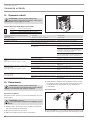
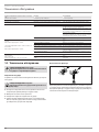
8. Appliance description
8.1 Standard delivery
The following are delivered with the appliance:
- Wall mounting bracket
- Threaded stud for wall mounting
- Installation template
- 2 twin connectors (cold water with shut-off valve)
- Flat gaskets
- Cable grommet (power cable from above/ below)
- Screws/ rawl plugs for fixing the back panel in the case of
water connection on finished walls
For appliance replacement:
- 2 tap extensions
9. Preparations
9.1 Installation site
!
Material losses
Install the appliance in a room free from the risk of frost.
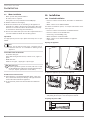
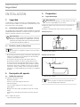
Always install the appliance vertically and near the draw-off
point.
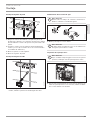
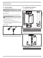
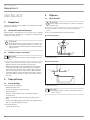
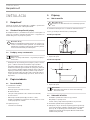
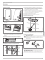
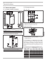
The appliance is suitable for undersink and oversink installation.
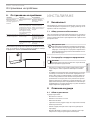
Undersink installation
26�02�02�1345
1
2
1 Cold waterInlet
2 DHW outlet
Oversink installation
12
26�02�02�1344
1 Cold waterInlet
2 DHW outlet
Note
Mount the appliance on the wall. The wall must have
a sufficient load-bearing capacity.

6 | PEG 13-24 www.stiebel-eltron.com
INSTALLATION
Installation
9.2 Water installation
- Never operate with preheated water.
- No safety valve is required.
- Safety valves are not permissible in the DHW pipe.
Flush the water line thoroughly.
Ensure that the flow rate for switching on the appliance is
achieved (see chapter "Specification/ Data table", On). If the
flow rate is not achieved, remove the flow limiter (see chap-
ter "Installation/ Removing the flow limiter").
Increase the mains water pressure if the required flow rate is
not achieved with the draw-off valve fully opened.
Taps/valves
Use appropriate pressure taps. Open vented taps are not per-
mitted.
Note
Never use the shut-off valve in the cold water inlet to
reduce the flow rate. It is intended for shutting off the
appliance.
Permissible water line materials
- Cold water inlet pipe:
Pipes made from galvanised steel, stainless steel, copper or
plastic
- DHW outlet line:
Stainless steel pipe, copper pipe or plastic pipe
!
Material losses
If plastic pipework systems are used, take into account
the maximum inlet temperature and the maximum pres-
sure (see chapter "Specification/ Data table").
Flexible water connection lines
If the appliance is installed with flexible water connection
lines, ensure that the bayonet fittings of the pipe bends do
not become twisted inside the appliance.
Secure the back panel at the bottom with two additional
screws.
10. Installation
10.1 Standard installation
- Electrical connection from above; installation on unfinished
walls
- Water connection on unfinished walls
For further installation options, see chapter "Alternative instal-
lation options":
- Electrical connection from below on unfinished walls
- Electrical connection on finished walls
- Connecting a load shedding relay
- Water installation on finished walls
- Water connection on unfinished walls for appliance
replacement
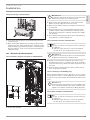
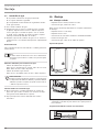
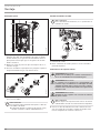
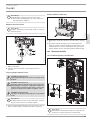
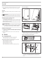
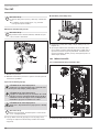
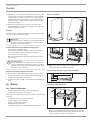
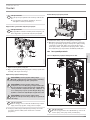
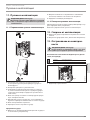
Opening the appliance
D0000041615
Open the appliance by releasing the snap lock.
NT
T-
so
X1
26�02�02�0762
Remove the back panel by pressing the two locking hooks
and pulling the base part of the back panel forwards.
Preparing the power cable
160
≥ 30
26�02�02�0887

ENGLISH
www.stiebel-eltron.com PEG 13-24 | 7
INSTALLATION
Installation
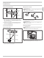
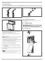
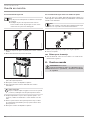
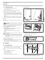
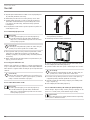
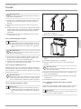
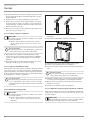
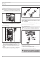
Fitting the wall mounting bracket
26�02�02�0972
Mark out the holes for drilling using the installation tem-
plate. If the appliance is to be installed with water connec-
tions on finished walls, also mark out the fixing holes in the
lower part of the template.
Drill the holes and secure the wall mounting bracket with
2screws and 2rawl plugs (screws and rawl plugs are not
part of the standard delivery).
Fit the threaded stud provided.
Fit the wall mounting bracket.
Fitting the cable grommet
26�02�02�0950
Fit the cable grommet. For connecting cables >6mm², en-
large the hole in the cable grommet.
Making the water connection
!
Material losses
Carry out all water connection and installation work in
accordance with regulations.
26�02�02�0948
Seal and insert the twin connectors.
!
Material losses
Never use the shut-off valve in the cold water inlet to
reduce the flow rate.
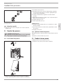
Preparing the back panel
!
Material losses
If you break open the wrong knock-out in the back panel
by mistake, you must use a new back panel.
L
L
L
D0000041893
Break out the cable grommet knock-out in the back panel.
Deburr any sharp edges with a file if necessary.

8 | PEG 13-24 www.stiebel-eltron.com
INSTALLATION
Installation
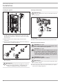
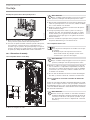
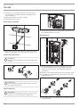
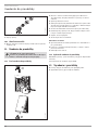
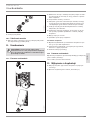
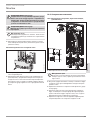
Installing the appliance
L
L
L
3
L3’
4
L2’
1
L1’
2
L
L
L
MV
NT C
T- soll
X1 1
D0000041894
Push the back panel over the threaded stud and the cable
grommet. Pull the cable grommet by the locking hooks into
the back panel using pliers, until both locking hooks audibly
click into place.
Remove the protective transport plugs from the water
connections.
Press the back panel firmly into place and lock the fixing tog-
gle by turning it clockwise through 90°.
D0000041925
Screw the water connection pipes with flat gaskets onto the
twin connectors.
!
Material losses
The strainer must be fitted for the appliance to function.
When replacing an appliance, check whether the
strainer is installed (see chapter "Maintenance").
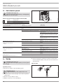
Removing the flow limiter
!
Material losses
If you use a thermostatic valve, the flow limiter must not
be removed.
L1’
2
L
L
L
X11
26�02�02�0771
2
1
1 Plastic profile washer
2 Flow limiter
Remove the flow limiter and refit the plastic profile washer.
Making the electrical connection
WARNING Electrocution
Carry out all electrical connection and installation work
in accordance with relevant regulations.
WARNING Electrocution
The connection to the power supply must be in the form
of a permanent connection in conjunction with the re-
movable cable grommet. Ensure the appliance can be
separated from the power supply by an isolator that dis-
connects all poles with at least 3mm contact separation.
WARNING Electrocution
Ensure that the appliance is earthed.
!
Material losses
Observe the type plate. The specified voltage must match
the mains voltage.
Connect the power cable to the mains terminal (see chapter
"Specification/ Wiring diagram").

ENGLISH
www.stiebel-eltron.com PEG 13-24 | 9
INSTALLATION
Installation
Fitting the base part of the back panel
3
L
3’
4
L
2’
1
L
1’
2
L
L
L
NT C
T- sol
l
X11
26�02�02�1348
Position the lower back panel on the main back panel and
click it into place.
Align the mounted appliance by loosening the fixing toggle,
aligning the power supply and back panel, and then re-tight-
ening the fixing toggle. If the back panel is not flush with the
wall, the appliance can be secured at the bottom with two
additional screws.
10.2 Alternative installation options
10.2.1 Electrical connection from below on unfinished walls
1
L1í
2
L
L
L
X11
26�02�02�0767
Fit the cable grommet.
!
Material losses
If you break open the wrong knock-out in the back panel
by mistake, you must use a new back panel.
Break out the cable grommet knock-out in the back panel.
Deburr any sharp edges with a file if necessary.
Reposition the mains terminal in the appliance from the top
to the bottom.
Push the back panel over the threaded stud and the cable
grommet. Pull the cable grommet by the locking hooks into
the back panel using pliers, until both locking hooks audibly
click into place.
Press the back panel firmly into place and lock the fixing tog-
gle by turning it clockwise through 90°.
10.2.2 Electrical connection on finished walls
Note
This type of connection changes the protection rating of
the appliance.
Change the type plate. Cross out "IP 25" and mark
the box "IP 24". Use a ballpoint pen to do this.
!
Material losses
If you break open the wrong knock-out in the back panel
by mistake, you must use a new back panel.
Cleanly cut or break out the required cable entries in the
back panel (for positions, see chapter "Specification/ Dimen-
sions and connections"). Deburr any sharp edges with a file if
necessary.
Route the power cable through the cable grommet and con-
nect it to the mains terminal.
10.2.3 Connecting a load shedding relay
When operating additional electric appliances, such as electric
storage heaters, install a load shedding relay in the distribution
board. The relay responds when the instantaneous water heater
starts.
!
Material losses
Connect the phase that switches the load shedding relay
to the indicated terminal of the mains terminal in the
appliance (see chapter "Specification/ Wiring diagram").
10.2.4 Water installation on finished walls
Note
This type of connection changes the protection rating of
the appliance.
Change the type plate. Cross out "IP 25" and mark
the box "IP 24". Use a ballpoint pen to do this.

10 | PEG 13-24 www.stiebel-eltron.com
INSTALLATION
Commissioning
26�02�02�0765
Fit water plugs with gaskets to seal the in-wall connection.
Fit a suitable pressure tap.
26�02�02�1006
Click the lower section of the back panel into place in the
upper section of the back panel.
Secure the connection pipes to the appliance.
Secure the back panel at the bottom with two additional
screws.
!
Material losses
If you break open the wrong knock-out in the back panel
by mistake, you must use a new back panel.
Cleanly break out the knock-outs in the appliance cover. De-
burr any sharp edges with a file if necessary.
Slide the lower back panel under the connection pipes of the
tap and click the lower back panel into place.
Secure the connection pipes to the appliance.
10.2.5 Water installation on unfinished walls for appliance
replacement
If the existing twin connectors of the old appliance only protrude
from the wall by approx.16mm, you cannot use the twin con-
nectors provided.
Note
With this connection, the cold water supply can only be
shut off within the domestic installation.
16
D0000041634
Seal and fit the screw-in tap extensions provided.
Connect the appliance.
10.3 Completing the installation
Open the shut-off valve in the twin connector or the cold
water inlet line.
11. Commissioning
WARNING Electrocution
Commissioning must only be carried out by a qualified
contractor in accordance with safety regulations.
11.1 Initial start-up
L
L
3
L
3’
4
L
2
’
1
L
1
’
2
MV
NT C
T- soll
18
2
1
24
k W
D0000041619

ENGLISH
www.stiebel-eltron.com PEG 13-24 | 11
INSTALLATION
Shutdown
Open and close all connected draw-off valves several times,
until all air has been purged from the pipework and the
appliance.
Carry out a tightness check.
Activate the safety pressure limiter by firmly pressing the
reset button (the appliance is delivered with the safety pres-
sure limiter deactivated).
Plug the temperature selector cable plug into the PCB.
Fit the appliance cover, ensuring it clicks into place. Check
that the appliance cover is seated correctly.
Switch the mains power ON.
Check the function of the appliance.
Appliance handover
Explain the appliance function to users and familiarise them
with its operation.
Make the user aware of potential dangers, especially the risk
of scalding.
Hand over these instructions.
11.2 Recommissioning
Vent the appliance and the cold water inlet line (see chapter "Set-
tings").
See chapter "Commissioning".
12. Shutdown
Isolate all poles of the appliance from the power supply.
Drain the appliance (see chapter "Maintenance").

12 | PEG 13-24 www.stiebel-eltron.com
INSTALLATION
Troubleshooting
13. Troubleshooting
WARNING Electrocution
To test the appliance, it must be supplied with power.
Indication variants for diagnostic traffic light (LED)
Red Illuminates in the event of a fault
Yellow Illuminates during heating operation
Green Flashing: Appliance is connected to power
supply
L
L
3
L
3’
4
L
2
’
1
L
1
’
2
MV
NT C
T- soll
18
2
1
24
k W
D0000041793
1
1 Diagnostic traffic light
Fault/ diagnostic traffic light LED display Cause Remedy
The flow rate is too low. The strainer in the appliance is dirty. Clean the strainer.
The set temperature is not achieved. One phase down. Check the fuse/MCB in your fuse box/distribution
panel.
The heating system does not switch on. Air has been detected in the water and heating out-
put is briefly switched off.
The appliance restarts after one minute.
No hot water and no traffic light display.
The MCB/fuse has responded/blown. Check the fuse/MCB in your fuse box/distribution
panel.
Safety pressure limiter AP 3 has tripped.
Remove the cause of the fault (e.g. faulty pressure
flush).
Protect the heating system against overheating by
opening a draw-off valve downstream of the appli-
ance for one minute. This depressurises and cools
down the heating system.
Activate the safety pressure limiter at flow pressure
by pressing the reset button (see chapter "Commis-
sioning").
The PCB is faulty. Check the PCB and replace if required.
Traffic light display: Green flashing or constantly on
The PCB is faulty. Check the PCB and replace if required.
No hot water at a flow rate >3l/min.
The flow meter (DFE) is not plugged in. Plug the flow meter plug back in.
The flow meter (DFE) is faulty. Check the flow meter and replace if required.
Traffic light display: yellow constantly on; green
flashing
The high limit safety cut-out has responded or suf-
fered a lead break.
Check the high limit safety cut-out and replace it if
required.
No hot water at a flow rate >3l/min.
The heating system is faulty. Check the heating system resistor and replace if re-
quired.
The PCB is faulty. Check the PCB and replace if required.
Traffic light display: red constantly on; green flashing
The cold water sensor is faulty. Check the PCB and replace if required.
No hot water
Required temperature > 45°C is not achieved.
The cold water inlet temperature is above 45°C. Reduce the cold water inlet temperature to the ap-
pliance.
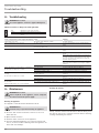
14. Maintenance
WARNING Electrocution
Before any work on the appliance, ensure omnipolar
disconnection from the power supply.
Draining the appliance
The appliance can be drained for maintenance work.
WARNING Burns
Hot water may escape when draining the appliance.
Close the shut-off valve in the twin connector or the cold
water inlet line.
Open all draw-off valves.
Undo the water connections on the appliance.
Store the dismantled appliance in a room free from the risk
of frost, as water residues remaining inside the appliance can
freeze and cause damage.
Cleaning the strainer
26�02�02�0949
If dirty, clean the strainer in the threaded cold water fitting. Close
the shut-off valve in the cold water inlet line before removing,
cleaning and refitting the strainer.

ENGLISH
www.stiebel-eltron.com PEG 13-24 | 13
INSTALLATION
Specication
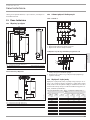
15. Specification
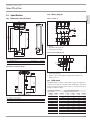
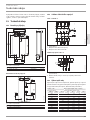
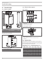
15.1 Dimensions and connections
395
100
485
325
45
5
93
226
190
50
112
190
35
c01
c06
b02
D0000017757
b02 Entry electrical cables I
c01 Cold waterInlet Male thread G 1/2 A
c06 DHW outlet Male thread G 1/2 A
Alternative connection options
325
50
50
35
40
b03
b02
b04
b04
b04
D0000019778
b02 Entry electrical cables I
b03 Entry electrical cables II
b04 Entry electrical cables III
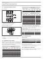
15.2 Wiring diagram
3/PE ~ 380-415 V
85�02�02�0005
1 Heater
2 High limit safety cut-out
3 Safety pressure limiter
Priority control with LR 1-A
85�02�02�0003�
2
1
1 Control cable to the contactor of the 2nd appliance (e.g. elec-
tric storage heater).
2 Control contact opens when switching the instantaneous
water heater on.
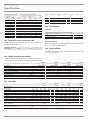
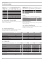
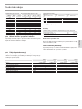
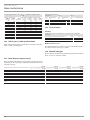
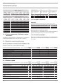
15.3 DHW output
The DHW output is subject to the mains voltage, the appliance's
connected load and the cold water inlet temperature. The rated
voltage and rated output can be found on the type plate (see
chapter "Troubleshooting").
Connected load in kW 38 °C DHW output in l/min.
Rated voltage Cold water inlet temperature
380 V 400 V 415 V 5°C 10°C 15°C 20°C
12,2 5,3 6,2 7,6 9,7
13,5 5,8 6,9 8,4 10,7
14,5 6,3 7,4 9,0 11,5
16,2 7,0 8,3 10,1 12,9
18 7,8 9,2 11,2 14,3
19,4 8,4 9,9 12,0 15,4
19 8,2 9,7 11,8 15,1
21 9,1 10,7 13,0 16,7
22,6 9,8 11,5 14,0 17,9
21,7 9,4 11,1 13,5 17,2
24 10,4 12,2 14,9 19,0
25,8 11,2 13,2 16,0 20,5

14 | PEG 13-24 www.stiebel-eltron.com
INSTALLATION
Specication
Connected load in kW 50 °C DHW output in l/min.
Rated voltage Cold water inlet temperature
380 V 400 V 415 V 5°C 10°C 15°C 20°C
12,2 3,9 4,4 5,0 5,8
13,5 4,3 4,8 5,5 6,4
14,5 4,6 5,2 5,9 6,9
16,2 5,1 5,8 6,6 7,7
18 5,7 6,4 7,3 8,6
19,4 6,2 6,9 7,9 9,2
19 6,0 6,8 7,8 9,0
21 6,7 7,5 8,6 10,0
22,6 7,2 8,1 9,2 10,8
21,7 6,9 7,8 8,9 10,3
24 7,6 8,6 9,8 11,4
25,8 8,2 9,2 10,5 12,3
15.4 Application areas/ conversion table
Specific electrical resistance and specific electrical conductivity
(see chapter "Data table").
Standard specifica-
tion at 15 °C
20°C
25°C
Resist-
ance
ρ ≥
Conductivity σ ≤
Resist-
ance
ρ ≥
Conductivity σ ≤
Resist-
ance
ρ ≥
Conductivity σ ≤
Ωcm mS/m μS/cm Ωcm mS/m μS/cm Ωcm mS/m μS/cm
1100 91 909 970 103 1031 895 112 1117
1200 83 833 1070 93 935 985 102 1015
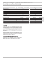
15.5 Pressure drop
Taps/valves
Tap pressure drop at a flow rate of 10 l/min
Mono lever mixer tap, approx. MPa 0.04 - 0.08
Thermostatic valve, approx. MPa 0.03 - 0.05
Shower head, approx. MPa 0.03 - 0.15
Sizing the pipework
When calculating the size of the pipework, an appliance pressure
drop of 0.1MPa is recommended.
15.6 Fault conditions
If a fault arises, loads of up to 95°C / 1.2MPa can temporarily
occur in the installation.
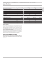
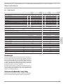
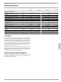
15.7 Details on energy consumption
The product data complies with EU regulations relating to the
Directive on the ecological design of energy related products (ErP).
PEG 13 PEG 18 PEG 21 PEG 24
233994 233995 233996 233997
Manufacturer STIEBEL ELTRON STIEBEL ELTRON STIEBEL ELTRON STIEBEL ELTRON
Load profile S S S S
Energy efficiency class A A A A
Annual power consumption kWh 465 480 477 475
Energy conversion efficiency % 40 39 39 39
Default temperature setting °C 55 55 55 55
Sound power level dB(A) 15 15 15 15
Special information on measuring efficiency None None None None
15.8 Data table
PEG 13 PEG 18 PEG 21 PEG 24
233994 233995 233996 233997
Electrical details
Rated voltage V 380 400 415 380 400 415 380 400 415 380 400 415
Rated output kW 12.2 13.5 14.5 16.2 18 19.4 19 21 22.6 21.7 24 25.8
Rated current A 18.5 19.5 20.2 24.7 26 27 29.5 31 32.2 33.3 35 36.3
Fuse A 20 20 20 25 25 32 32 32 32 35 35 40
Phases 3/PE 3/PE 3/PE 3/PE
Frequency Hz 50/60 50/60 50/- 50/60 50/60 50/- 50/60 50/60 50/- 50/60 50/60 50/-
Max. mains impedance at 50Hz Ω 0.379 0.360 0.347 0.325 0.308 0.297 0.284 0.270 0.260
Specific resistance ρ
15
≥ (at ϑcold ≤25 °C) Ω cm 1100 1100 1200 1100 1100 1200 1100 1100 1200 1100 1100 1200
Specific conductivity σ
15
≤ (at ϑcold ≤25°C) μS/cm 900 900 833 900 900 833 900 900 833 900 900 833
Connections
Water connection G 1/2 A G 1/2 A G 1/2 A G 1/2 A
Application limits
Max. permissible pressure MPa 1 1 1 1

ENGLISH
www.stiebel-eltron.com PEG 13-24 | 15
INSTALLATION | GUARANTEE | ENVIRONMENT AND RECYCLING
Specication
PEG 13 PEG 18 PEG 21 PEG 24
Values
Max. permissible inlet temperature °C 35 35 35 35
ON l/min >3.0 >3.0 >3.0 >3.0
Flow rate for pressure drop l/min 3.9 5.2 6.0 6.9
Pressure drop at flow rate MPa 0.11 (0.03 without DMB) 0.08 (0.06 without DMB) 0.1 (0.08 without DMB) 0.13 (0.1 without DMB)
Flow rate limit at l/min 4.0 8.0 8.0 9.0
DHW delivery l/min 6.7 9.4 11.6 12.6
Δϑ at DHW delivery K 26 26 26 26
Hydraulic data
Rated capacity l 0.4 0.4 0.4 0.4
Versions
Temperature adjustment °C 42/55 42/55 42/55 42/55
Protection class 1 1 1 1
Heating system heat generator Bare wire Bare wire Bare wire Bare wire
IP-Rating IP25 IP25 IP25 IP25
Dimensions
Height mm 485 485 485 485
Width mm 226 226 226 226
Depth mm 93 93 93 93
Weights
Weight kg 3.6 3.6 3.6 3.6
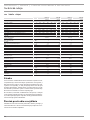
Guarantee
The guarantee conditions of our German companies do not
apply to appliances acquired outside of Germany. In countries
where our subsidiaries sell our products a guarantee can only
be issued by those subsidiaries. Such guarantee is only grant
-
ed if the subsidiary has issued its own terms of guarantee. No
other guarantee will be granted.
We shall not provide any guarantee for appliances acquired in
countries where we have no subsidiary to sell our products.
This will not aect warranties issued by any importers.
Environment and recycling
We would ask you to help protect the environment.
After use,
dispose of the various materials in accordance with national
regulations.
GUARANTEE
ENVIRONMENT AND RECYCLING

16 | PEG 13-24 www.stiebel-eltron.com
CONTENIDO | INDICACIONES ESPECIALES
INDICACIONES ESPE-
CIALES
- El aparato puede ser utilizado por niños a partir
de 3 años, así como por personas con capaci-
dades físicas, sensoriales o mentales limitadas,
o con falta de experiencia y conocimientos, solo
bajo la vigilancia de otra persona o si antes han
recibido instrucciones sobre el uso seguro del
aparato y han comprendido los peligros que
pueden derivarse. No deje que los niños jueguen
con el aparato. Las tareas de limpieza y manteni-
miento propias del usuario no deben ser realiza-
das por niños sin vigilancia.
- Los grifos/válvulas pueden calentarse a más de
60°C. A temperaturas de salida superiores a
43°C existe peligro de escaldamiento.
- El aparato debe poder desconectarse omnipolar-
mente de la red eléctrica mediante una separa-
ción de al menos 3mm.
- La tensión indicada debe coincidir con la tensión
de red disponible.
- El equipo debe estar conectado a un contacto de
protección.
- El equipo debe estar conectado a un contacto de
protección.
- Fije el aparato tal como se describe en el capítulo
"Instalación/ Montaje".
- Tenga en cuenta la presión máxima admisible
(consulte el capítulo "Especificaciones técnicas/
Tabla de especificaciones").
- La resistencia específica del agua de la red de
abastecimiento de agua no debe tener un valor
inferior al mínimo (véase el capítulo „Insta-
lación / Especificaciones técnicas / Tabla de
especificaciones“).
- Vacíe el aparato tal y como se describe en el ca-
pítulo "Instalación/ Mantenimiento/ Vaciado del
aparato".
INDICACIONES ESPECIALES
OPERACIÓN
1. Indicaciones generales ������������������������������������� 17
1.1 Instrucciones de seguridad������������������������������������17
1.2 Otras marcas presentes en esta documentación ���������� 17
1.3 Unidades de medida �������������������������������������������17
2. Seguridad ��������������������������������������������������� 17
2.1 Utilización conforme a las prescripciones ������������������ 17
2.2 Instrucciones generales de seguridad ����������������������17
2.3 Sello de certificación �������������������������������������������17
3. Descripción del aparato ������������������������������������ 18
4. Configuración ����������������������������������������������� 18
5. Limpieza, conservación y mantenimiento ���������������� 18
6. Resolución de problemas ���������������������������������� 18
INSTALACIÓN
7. Seguridad ��������������������������������������������������� 19
7.1 Instrucciones generales de seguridad ����������������������19
7.2 Directivas, normas y disposiciones �������������������������� 19
8. Descripción del aparato ������������������������������������ 19
8.1 Ámbito de suministro ������������������������������������������ 19
9. Preparativos ������������������������������������������������� 19
9.1 Lugar de montaje ����������������������������������������������� 19
9.2 Instalación de agua ��������������������������������������������� 20
10. Montaje ������������������������������������������������������ 20
10.1 Montaje estándar �����������������������������������������������20
10.2 Alternativas de montaje ���������������������������������������23
10.3 Últimos pasos de montaje ������������������������������������24
11. Puesta en marcha ������������������������������������������ 24
11.1 Primera puesta en marcha ������������������������������������ 25
11.2 Nueva puesta en marcha �������������������������������������� 25
12. Puesta fuera de servicio ����������������������������������� 25
13. Localización y reparación de averías ��������������������� 26
14. Mantenimiento ���������������������������������������������� 27
15. Especificaciones técnicas ���������������������������������� 27
15.1 Dimensiones y conexiones ������������������������������������27
15.2 Esquema de conexiones eléctricas �������������������������� 28
15.3 Rendimiento de agua caliente �������������������������������28
15.4 Ámbitos de aplicación/ Tabla de conversión ��������������28
15.5 Pérdida de presión ���������������������������������������������� 28
15.6 Condiciones en caso de avería �������������������������������28
15.7 Datos sobre el consumo energético ������������������������� 29
15.8 Tabla de especificaciones ��������������������������������������29
GARANTÍA
MEDIO AMBIENTE Y RECICLADO

OPERACIÓN
Indicaciones generales
ESPAÑOL
www.stiebel-eltron.com PEG 13-24 | 17
OPERACIÓN
1. Indicaciones generales
Los capítulos "Indicaciones especiales" y "Operación" están dirigi-
dos al usuario del aparato y al profesional técnico especializado.
El capítulo "Instalación" está dirigido al profesional técnico espe-
cializado.
Nota
Lea atentamente estas instrucciones antes del uso y ar-
chívelas en un lugar seguro.
Si entrega este aparato a otros usuarios, no olvide incluir
las instrucciones.
1.1 Instrucciones de seguridad
1.1.1 Estructura de las instrucciones de seguridad
!
PALABRA DE ADVERTENCIA Tipo de peligro
Mediante este tipo de palabras se explican las posibles
consecuencias en caso de desobedecimiento de las ins-
trucciones de seguridad.
Aquí se proponen las medidas necesarias para evitar
el peligro.
1.1.2 Símbolos, tipo de peligro
Símbolo Tipo de peligro
Lesión
Electrocución
Quemaduras
(quemaduras, escaldadura)
1.1.3 Palabras de advertencia
PALABRA DE
ADVERTENCIA
Significado
PELIGRO Indicaciones cuyo desobedecimiento tiene como consecuen-
cia lesiones graves o la muerte.
ADVERTENCIA Indicaciones cuyo desobedecimiento puede tener como con-
secuencia lesiones graves o la muerte.
PRECAUCIÓN Indicaciones cuyo desobedecimiento puede tener como con-
secuencia lesiones de gravedad media o baja.
1.2 Otras marcas presentes en esta documentación
Nota
Las indicaciones generales se señalizan mediante el sím-
bolo adyacente.
Lea atentamente las indicaciones.
Símbolo Significado
Daños materiales
(daños en el aparato, indirectos, medioambientales)
Eliminación del aparato
Este símbolo le indica que usted tiene que hacer algo. Se des-
criben paso a paso las medidas necesarias.
1.3 Unidades de medida
Nota
Si no se indica lo contrario, todas las dimensiones estarán
expresadas en milímetros.
2. Seguridad
2.1 Utilización conforme a las prescripciones
El aparato está previsto para utilizarse en un ámbito doméstico.
Personas no instruidas lo pueden manejar de forma segura. El
aparato puede utilizarse igualmente en ámbitos que no sean do-
mésticos, como en pequeñas empresas, siempre que se maneje
del mismo modo.
El aparato a presión sirve para calentar agua potable. El aparato
puede alimentar uno o varios puntos de dispensado.
Cualquier otro uso distinto al aquí previsto se considera un uso
indebido. Se considera uso previsto el cumplimiento de estas ins-
trucciones, así como las instrucciones de los accesorios utilizados.
2.2 Instrucciones generales de seguridad
PRECAUCIÓN Quemaduras
Los grifos/válvulas pueden calentarse durante el funcio-
namiento a más de 60°C.
A temperaturas de salida superiores a 43°C existe peligro
de escaldamiento.
!
ADVERTENCIA Lesiones
El aparato puede ser utilizado por niños a partir de 3
años, así como por personas con capacidades físicas, sen-
soriales o mentales limitadas, o con falta de experiencia
y conocimientos, solo bajo la vigilancia de otra persona
o si antes han recibido instrucciones sobre el uso seguro
del aparato y han comprendido los peligros que pueden
derivarse. No deje que los niños jueguen con el apara-
to. Las tareas de limpieza y mantenimiento propias del
usuario no deben ser realizadas por niños sin vigilancia.
!
Daños materiales
El usuario debe proteger el aparato y los grifos/válvulas
frente a la formación de escarcha.
2.3 Sello de certificación
Véase placa de especificaciones técnicas en el aparato.
!
!

OPERACIÓN
Descripción del aparato
18 | PEG 13-24 www.stiebel-eltron.com
3. Descripción del aparato
Puede ajustar la temperatura de salida del agua caliente mediante
el selector de temperatura. A partir de un caudal de aprox. 3 l/min,
el control ajusta la potencia de calefacción adecuada en función del
ajuste de temperatura y de la temperatura del agua fría.
Sistema de calefacción
El sistema de calefacción de cables desnudos tiene una capa de
plástico estanca a la presión. El sistema de calefacción es apto
para agua tanto pobre como rica en cal, ya que es resistente a
la acumulación de cal. El sistema de calefacción abastece agua
caliente de forma rápida y eficaz.
Nota
El aparato está equipado con un sistema de detección de
aire que evita que se produzcan daños en el sistema de
calefacción. Si durante el funcionamiento entra aire en el
aparato, el aparato desconectará la potencia de calefac-
ción durante un minuto, con lo que protegerá el sistema
de calefacción.
4. Configuración
Puede ajustar la temperatura de salida del agua caliente en 2
niveles.
1 2
D0000041611
1 Ducha (42°C)
2 Fregadero de la cocina (55°C)
Encaje el selector de temperatura en la posición deseada.
Nota
Si con la válvula de dispensado totalmente abierta y la
configuración de temperatura al máximo (fregadero de la
cocina) no se alcanza una temperatura de salida suficien-
te, a través del aparato fluirá un caudal de agua mayor
que el que el sistema de calefacción es capaz de calentar
(aparato en el límite de potencia).
Reduzca el caudal de agua en la válvula de dispen-
sado.
Recomendación de configuración en caso de funcionamiento con
una válvula del termostato
Configure la temperatura del aparato a la temperatura máxima
(fregadero de la cocina).
Tras interrumpir el abastecimiento de agua
!
Daños materiales
Tras una interrupción en el abastecimiento de agua, es
necesario volver a poner en marcha el aparato según las
siguientes instrucciones para no destruir el sistema de
calefacción de cables desnudos.
Desenergice el aparato desconectando los fusibles.
Abra el grifo durante un minuto hasta que no quede
aire en el aparato ni en el tubo de alimentación de
agua fría conectada antes.
Vuelva a encender la alimentación eléctrica.
5. Limpieza, conservación y manteni-
miento
No utilice detergentes agresivos ni disolventes. Para conservar
y limpiar el aparato basta con utilizar un paño húmedo.
Revise la grifería/valvulería periódicamente. La cal en las
tomas de grifos puede eliminarse utilizando los productos
antical disponibles en el mercado.
6. Resolución de problemas
Problema Causa Solución
El aparato no se enciende
a pesar de que la válvula
de agua caliente está
completamente abierta.
No hay tensión.
Revise los fusibles de la
caja de fusibles domés-
tica.
El caudal es demasiado
pequeño para encender
la potencia de calefacción.
El regulador de chorro en
el grifo o el cabezal de
la ducha presentan cal o
están sucios.
Limpie y/o elimine la cal
del regulador de chorro o
del cabezal de la ducha.
No se alcanza la tempera-
tura deseada > 45°C.
El abastecimiento de agua
está interrumpido.
Purgue el aire del aparato
y del tubo de alimenta-
ción de agua fría (consul-
te el capítulo "Configura-
ción").
La temperatura de ad-
misión del agua fría es
> 45°C.
Reduzca la temperatura
de admisión del agua fría.
Si no puede solucionar la causa, llame al profesional técnico espe-
cializado. Para poder ayudarle mejor y con mayor rapidez, indique
el número de la placa de especificaciones técnicas (000000-0000-
00000):
Nr.: 000000-0000-00000
D0000041614

ESPAÑOL
www.stiebel-eltron.com PEG 13-24 | 19
INSTALACIÓN
Seguridad
INSTALACIÓN
7. Seguridad
La instalación, la puesta en marcha y el mantenimiento y repa-
ración del aparato deben ser realizados exclusivamente por un
profesional técnico especializado.
7.1 Instrucciones generales de seguridad
Solo garantizamos un nivel óptimo de funcionalidad y de seguridad
y fiabilidad de funcionamiento si se utilizan accesorios y piezas de
repuesto originales específicos para el aparato.
!
Daños materiales
Tenga en cuenta la temperatura máxima de admisión.
El aparato se puede dañar si la temperatura es elevada.
Instalando una válvula termostática central puede limitar
la temperatura máxima de admisión.
7.2 Directivas, normas y disposiciones
Nota
Observe todos los reglamentos y disposiciones nacionales
y regionales.
- El tipo de protección IP 25 (protección frente a salpicaduras de
agua) solo se garantiza con un manguito de cable montado
conforme a la normativa vigente.
- La resistencia eléctrica específica del agua no debe ser
menor que la indicada en la placa de especificaciones téc-
nicas. En una red colectiva de agua debe tenerse en cuenta
la resistencia eléctrica mínima del agua (consulte el capítulo
"Especificaciones técnicas / Ámbitos de aplicación / Tabla de
conversión"). Puede consultar cuál es la resistencia eléctrica
específica o la conductividad eléctrica del agua a su compañía
de aguas.
8. Descripción del aparato
8.1 Ámbito de suministro
El suministro del aparato incluye:
- Enganche de pared
- Pernos roscados para enganche de pared
- Patrón de montaje
- 2 racores dobles (agua fría con válvula de cierre)
- Juntas planas
- Manguito del cable (cable de alimentación eléctrica arriba/
abajo)
- Tornillos/tacos para fijación en pared en conexión de agua
vista
Para el cambio del aparato:
- 2 prolongaciones de grifo
9. Preparativos
9.1 Lugar de montaje
!
Daños materiales
La instalación del aparato solo debe realizarse en habi-
taciones resguardadas de la escarcha.
Monte el aparato en posición vertical y cerca del punto de
dispensado.
El aparato se puede montar sobre una mesa y bajo mesa.
Montaje bajo mesa
26�02�02�1345
1
2
1 Alimentación del agua fría
2 Salida de agua caliente
Montaje sobre una mesa
12
26�02�02�1344
1 Alimentación del agua fría
2 Salida de agua caliente
Nota
Monte el aparato en la pared. La pared debe tener
una capacidad portante suficiente.

20 | PEG 13-24 www.stiebel-eltron.com
INSTALACIÓN
Montaje
9.2 Instalación de agua
- No se permite la utilización de agua precalentada.
- No se requiere válvula de seguridad.
- ¡No está permitido instalar válvulas de seguridad en la tube-
ría de agua caliente!
Lave a fondo la tubería de agua.
Asegúrese de que se alcance el caudal necesario (consulte
el capítulo "Especificaciones técnicas / Tabla de especifica-
ciones") para que se encienda el aparato. Si no se alcanza
el caudal, retire el limitador de caudal (consulte el capítulo
"Montaje / Retirada del limitador de caudal").
Aumente la presión de la tubería de agua si no se alcanza el
caudal necesario con la válvula de dispensado completamente
abierta.
Grifería/valvulería
Utilice valvulería de presión adecuada. No se admite grifería/val-
vulería abierta.
Nota
No debe utilizar la válvula de cierre en la alimentación
del agua fría para reducir el caudal. Sirve para bloquear
el aparato.
Materiales admisibles para las tuberías de agua
- Tubería de alimentación de agua fría:
tubos de acero galvanizados en caliente, tubos de acero inoxi-
dable, tubos de cobre o tubos de plástico
- Tubería de salida de agua caliente:
tubos de acero inoxidable, tubos de cobre o tubos de plástico
!
Daños materiales
Si utiliza sistemas de tuberías de plástico, tenga presente
la temperatura de admisión máxima y la presión máxima
admisible (consulte el capítulo "Especificaciones técnicas
/ Tabla de especificaciones").
Tuberías flexibles de conexión de agua
En las instalaciones con tuberías flexibles de conexión de
agua, evite que los tubos acodados con conexiones de bayo-
neta giren de forma indebida en el aparato.
Fije la pared posterior inferior utilizando dos tornillos
adicionales.
10. Montaje
10.1 Montaje estándar
- Empalme eléctrico arriba, instalación oculta
- Conexión de agua, instalación oculta
Otras opciones de montaje disponibles en el capítulo "Alternativas
de montaje".
- Empalme eléctrico oculto abajo
- Empalme eléctrico visto
- Conexión de un controlador automático de máxima demanda
- Instalación de agua vista
- Conexión de agua oculta en un cambio de aparato
Apertura del aparato
D0000041615
Abra el aparato desbloqueando el cierre de inserción.
NT
T-
so
X1
26�02�02�0762
Separe la pared posterior apretando los dos ganchos de en-
clavamiento y retirando la parte inferior de la pared posterior
hacia adelante.
Preparación del cable de conexión a la red eléctrica
160
≥ 30
26�02�02�0887
Strona się ładuje...
Strona się ładuje...
Strona się ładuje...
Strona się ładuje...
Strona się ładuje...
Strona się ładuje...
Strona się ładuje...
Strona się ładuje...
Strona się ładuje...
Strona się ładuje...
Strona się ładuje...
Strona się ładuje...
Strona się ładuje...
Strona się ładuje...
Strona się ładuje...
Strona się ładuje...
Strona się ładuje...
Strona się ładuje...
Strona się ładuje...
Strona się ładuje...
Strona się ładuje...
Strona się ładuje...
Strona się ładuje...
Strona się ładuje...
Strona się ładuje...
Strona się ładuje...
Strona się ładuje...
Strona się ładuje...
Strona się ładuje...
Strona się ładuje...
Strona się ładuje...
Strona się ładuje...
Strona się ładuje...
Strona się ładuje...
Strona się ładuje...
Strona się ładuje...
Strona się ładuje...
Strona się ładuje...
Strona się ładuje...
Strona się ładuje...
Strona się ładuje...
Strona się ładuje...
Strona się ładuje...
Strona się ładuje...
Strona się ładuje...
Strona się ładuje...
Strona się ładuje...
Strona się ładuje...
Strona się ładuje...
Strona się ładuje...
Strona się ładuje...
Strona się ładuje...
Strona się ładuje...
Strona się ładuje...
Strona się ładuje...
Strona się ładuje...
Strona się ładuje...
Strona się ładuje...
Strona się ładuje...
Strona się ładuje...
Strona się ładuje...
Strona się ładuje...
Strona się ładuje...
Strona się ładuje...
-
 1
1
-
 2
2
-
 3
3
-
 4
4
-
 5
5
-
 6
6
-
 7
7
-
 8
8
-
 9
9
-
 10
10
-
 11
11
-
 12
12
-
 13
13
-
 14
14
-
 15
15
-
 16
16
-
 17
17
-
 18
18
-
 19
19
-
 20
20
-
 21
21
-
 22
22
-
 23
23
-
 24
24
-
 25
25
-
 26
26
-
 27
27
-
 28
28
-
 29
29
-
 30
30
-
 31
31
-
 32
32
-
 33
33
-
 34
34
-
 35
35
-
 36
36
-
 37
37
-
 38
38
-
 39
39
-
 40
40
-
 41
41
-
 42
42
-
 43
43
-
 44
44
-
 45
45
-
 46
46
-
 47
47
-
 48
48
-
 49
49
-
 50
50
-
 51
51
-
 52
52
-
 53
53
-
 54
54
-
 55
55
-
 56
56
-
 57
57
-
 58
58
-
 59
59
-
 60
60
-
 61
61
-
 62
62
-
 63
63
-
 64
64
-
 65
65
-
 66
66
-
 67
67
-
 68
68
-
 69
69
-
 70
70
-
 71
71
-
 72
72
-
 73
73
-
 74
74
-
 75
75
-
 76
76
-
 77
77
-
 78
78
-
 79
79
-
 80
80
-
 81
81
-
 82
82
-
 83
83
-
 84
84


STIEBEL ELTRON PEG 13-24 Operation Instruction
- Typ
- Operation Instruction
w innych językach
- español: STIEBEL ELTRON PEG 13-24
- slovenčina: STIEBEL ELTRON PEG 13-24
Powiązane artykuły
-
STIEBEL ELTRON PEO 18-27 Operation Instruction
-
-
-
-
-
STIEBEL ELTRON PEY Operation Instruction
-
-
-
-
Inne dokumenty
-
Kernau KGS A 50 1B1D SAND Instrukcja obsługi
-
-
-
-
-
DeLOCK 41432 Karta katalogowa
-
DeLOCK 41431 Karta katalogowa
-
Sulzer XRCP Instrukcja obsługi
-
Sanela SLS 01AKV Mounting instructions
-