AAT NVIP-8DN7560H/IRH-2P Instrukcja obsługi
- Kategoria
- Kamery ochrony
- Typ
- Instrukcja obsługi

U s e r ’s m a n u a l
(s h ort form )
NVIP-8DN7560H/IRH-2P

NVIP-8DN7560H/IRH-2P User’s manual ver.1.1 (short form)
All rights reserved © AAT Holding S.A.
2
IMPORTANT SAFEGUARDS AND WARNINGS
EMC (2004/108/EC) and LVD (2006/95/EC ) Directives
CE Marking
Our products are manufactured to comply with requirements of the following directives and national regulations
implementing the directives:
Electromagnetic compatibility EMC 2004/108/EC.
Low voltage LVD 2006/95/EC with further amendment. The Directive applies to electrical
equipment designed for use with a voltage rating of between 50VAC and 1000VAC as well as
75VDC and 1500VDC.
WEEE Directive 2012/19/EU
Information on Disposal for Users of Waste Electrical and Electronic Equipment
This appliance is marked according to the European 1000VAC Directive on Waste Electrical and Electronic
Equipment (2002/96/EC) and further amendments. By ensuring this product is disposed of correctly, you will
help to prevent potential negative consequences for the environment and human health, which could otherwise
be caused by inappropriate waste handling of this product.
The symbol on the product, or the documents accompanying the product, indicates that this appliance may not be
treated as household waste. It shall be handed over to the applicable collection point for used up electrical and
electronic equipment for recycling purpose. For more information about recycling of this product, please contact
your local authorities, your household waste disposal service or the shop where you purchased the product.
RoHS Directive 2011/65/EU
Out of concern for human health protection and friendly environment, we assure that our products
falling under RoHS Directive regulations, regarding the restriction of the use of hazardous substances
in electrical and electronic equipment, have been designed and manufactured in compliance with the
above mentioned regulations. Simultaneously, we claim that our products have been tested and do
not contain hazardous substances whose exceeding limits could have negative impact on human
health or natural environment
Information
The device, as a part of professional CCTV system used for surveillance and control, is not designed for self
installation in households by individuals without technical knowledge.
Excluding of responsibility in case of damaging data on a disk or other devices:
The manufacturer does not bear any responsibility in case of damaging or losing data on a disk or other devices
during device operation.
WARNING!
PRIOR TO UNDERTAKING ANY ACTION THAT IS NOT DESCRIBED FOR THE GIVEN PRODUCT IN
USER’S MANUAL AND OTHER DOCUMENTS DELIVERED WITH THE PRODUCT, OR IF IT DOES
NOT ARISE FROM THE USUAL APPLICATION OF THE PRODUCT, MANUFACTURER MUST BE
CONTACTED UNDER THE RIGOR OF EXCLUDING THE MANUFACTURER’S RESPONSIBILITY FOR
THE RESULTS OF SUCH AN ACTION.

NVIP-8DN7560H/IRH-2P User’s manual ver.1.1 (short form)
All rights reserved © AAT Holding S.A.
3
IMPORTANT SAFEGUARDS AND WARNINGS
WARNING!
THE KNOWLEDGE OF THIS MANUAL IS AN INDESPENSIBLE CONDITION OF A PROPER
DEVICE OPERATION. YOU ARE KINDLY REQUSTED TO FAMILIRIZE YOURSELF WITH
THE MANUAL PRIOR TO INSTALLATION AND FURTHER DEVICE OPERATION.
WARNING!
USER IS NOT ALLOWED TO DISASSEMBLE THE CASING AS THERE ARE NO USER
-SERVICEABLE PARTS INSIDE THIS UNIT. ONLY AUTHORIZED SERVICE PERSONNEL
MAY OPEN THE UNIT
INSTALLATION AND SERVICING SHOULD ONLY BE DONE BY QUALIFIED SERVICE
PERSONNEL AND SHOULD CONFORM TO ALL LOCAL REGULATIONS
1. Prior to undertaking any action please consult the following manual and read all the safety and operating
instructions before starting the device.
2. Please keep this manual for the lifespan of the device in case referring to the contents of this manual is
necessary;
3. All the safety precautions referred to in this manual should be strictly followed, as they have a direct
influence on user’s safety and durability and reliability of the device;
4. All actions conducted by the servicemen and users must be accomplished in accordance with the user’s
manual;
5. The device should be disconnected from power sources during maintenance procedures;
6. Usage of additional devices and components neither provided nor recommended by the producer is
forbidden;
7. You are not allowed to use the camera in high humidity environment (i.e. close to swimming pools, bath tubs,
damp basements);
8. Mounting the device in places where proper ventilation cannot be provided (e. g. closed lockers etc.) is not
recommended since it may lead to heat build-up and damaging the device itself as a consequence;
9. Mounting the camera on unstable surface or using not recommended mounts is forbidden. Improperly
mounted camera may cause a fatal accident or may be seriously damaged itself. The camera must be mounted
by qualified personnel with proper authorization, in accordance with this user’s manual.
10. Device should be supplied only from a power sources whose parameters are in accordance with those
specified by the producer in the camera technical datasheet. Therefore, it is forbidden to supply the camera
from a power sources with unknown parameters, unstable or not meeting producer’s requirements;
Due to the product being constantly enhanced and optimized, certain parameters and functions described in the
manual in question may change without further notice. We strongly suggest visiting the www.novuscctv.com
website in order to access the newest manual
Data included in the following user’s manual is up to date at the time of printing. AAT Holding Sp z o.o. holds
exclusive rights to modify this manual. The producer reserves the rights for device specification modification
and change in the design without prior notice.

NVIP-8DN7560H/IRH-2P User’s manual ver.1.1 (short form)
All rights reserved © AAT Holding S.A.
4
TABLE OF CONTENTS ..................................................................................................... 4
1. FOREWORD INFORMATION ................................................................................... ..5
1.1. General Characteristics ........................................................................................ 5
1.2. NVIP-8DN7560H/IRH-2P tech specification ................................................. ...6
1.3. Camera dimension ........................................................................................... ...7
1.4. Package contents ............................................................................................... ...8
2. START-UP AND INITIAL IP CAMERA CONFIGURATION ................................. 9
2.1. Description of connectors and control tools ........................................................ 9
2.2. Connecting power supply to the camera ........................................................... 10
2.3. NVIP-8DN7560H/IRH-2P mounting ................................................................ 10
2.4. Desiccant mounting guide ................................................................................ 12
2.5. Starting the IP camera ........................................................................................ 13
2.6. Initial configuration via the Web browser ......................................................... 14
3. NETWORK CONNECTION UTILIZING WEB BROSWER ................................ 15
3.1. Recommended PC specification for web browser ............................................. 15
3.2. Connection with IP camera via the Internet Explorer ........................................ 15
3.3. Connection with IP camera via the other browser ............................................. 17
4. WWW INTERFACE - WORKING WITH IP CAMERA ......................................... 19
4.1. Displaying live pictures. ..................................................................................... 19
5. ELECTRIC CONNECTORS AND ACCESORIES ................................................. 21
5.1. Connecting power supply to the camera. .......................................................... 21
5.1. Connecting alarm input and output .................................................................... 21
5.2. SD card installation ........................................................................................... 22
6. RESTORING FACTORY DEFAULTS ..................................................................... 23
6.1. Restoring software factory defaults .................................................................... 23
6.2. Restoring hardware factory defaults in IP cameras ........................................... 23
TABLE OF CONTENTS

NVIP-8DN7560H/IRH-2P User’s manual ver.1.1 (short form)
All rights reserved © AAT Holding S.A.
5
1. FOREWORD INFORMATION
1.1. General Characteristics
Mechanical IR cut filter
IR operation capability
Imager resolution: 8.0 megapixels
Min. Illumination: from 0.005 lx/F=1.45 (0 lx - IR On)
Wide Dynamic Range (WDR)
Digital Slow Shutter (DSS)
Digital Noise reduction (DNR)
Lens with remote focal and focus control 3.5 ~ 8 mm (F1.45)
Built-in IR LED - 6 pcs.
Privacy zones: 5
1 alarm input and output
Built-in webserver: video and audio compression and real-time network transmission
Compression: H.264, M-JPEG
Video processing resolution: - 3840 x 2160, 3200 x 1800, 1920 x 1080, 1280 x 1024, 1280 x 720,
1024 x 768, 800 x 600, 720 x 576, 640 x 480, 352 x 288
4 streams: compression, resolution, speed and quality defined individually for all video streams
RTP/RTSP protocol support for video transmission
Network connection control and IP address check function
Pre- & post-alarm functions - video recording in AVI format
Schedule recording function
Hardware motion detection
Audio detection
Bidirectional audio transmission
Micro SD/SDHC/SDXC card support
Diverse definition of system reactions to alarm events: e-mail with attachment, saving file on FTP
server, NAS, alarm output trigger, saving file on micro SD/SDHC/SDXC card, HTTP notification
Software: NMS (NOVUS MANAGEMENT SYSTEM) for video recording, live monitoring,
playback and remote IP devices administration
IP 66
Built-in heater
Power supply: 24 VAC, 12VDC, PoE (Power over Ethernet)
FOREWORD INFORMATION

NVIP-8DN7560H/IRH-2P User’s manual ver.1.1 (short form)
All rights reserved © AAT Holding S.A.
6
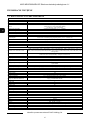
1.2. NVIP-8DN7560H/IRH-2P specification
FOREWORD INFORMATION
NVIP-8DN7560H/IRH-2P
IMAGE
Pick-up Element 8 MPX, CMOS imager, 1/1.7” SONY
Number of Effective Pixels 3840 (H) x 2160 (V)
Min. Illumination
0.05 lx/F=1.4 - color mode DSS,
0.005 lx/F=1.4 - B/W mode DSS,
0 lx (IR on) - B/W mode
Digital Slow Shutter (DSS)
Automatic/Manual 1/1 s ~ 1/10000 s
Wide Dynamic Range (WDR) Yes
Digital Noise Reduction (DNR) 3D
LENS
Type motor-zoom, auto-iris (P-Iris) function, f=3.5 ~ 8 mm/F1.45
Autofocus zoom trigger, day/night mode trigger, manual trigger
Angle of View (H) 116° - 52°
DAY/NIGHT
Type Mechanical IR cut filter
Switching Mode Auto/manual/light sensor/smart/external/time
NETWORK
Stream Resolution
3840 x 2160 (UHD), 3200 x 1800 (QHD+), 1920 x 1080 (Full HD), 1280 x 1024 (SXGA), 1280 x
720 (HD), 1024 x 768 (XGA), 800 x 600 (SVGA), 720 x 576 (D1), 640 x 480 (VGA), 352 x 288
(CIF), 320 x 240 (QVGA)
Frame Rate
30 fps for 3840 x 2160 and lower resolutions
60 fps for 1920 x 1080 and lower resolutions
Multistreaming Mode 4 streams
Video/Audio Compression H.264, M-JPEG/G.711, G.726
Number of simultaneous connections 10
Capacity
70 Mb/s
Network Protocols Support
HTTP, TCP/IP, IPv4/v6, UDP, HTTPS, Multicast, FTP, DHCP, DDNS, NTP, RTSP, RTP, UPnP,
SNMP, QoS, PPPoE
ONVIF Protocols Support
Profile S (ONVIF 2.4)
PC Software NOVUS NMS
OTHER FUNCTIONS
OSD IE browser, Polish, English, Russian and others
Privacy Zones 5
Motion Detection Yes
Prealarm/Postalarm 20 frames or 3 s/20 frames or 9999 s
System Reaction to Alarm Events
E-mail with attachment, saving file on: FTP server, NAS server, micro SD/SDHC card, output acti-
vation, HTTP notification
IR LED
Number 6
Range 50 m
Angle 60°
INTERFACES
Video Output 1 x BNC, 1.0 Vp-p, 75 Ohm - maintenance only
Audio Input/Output 1 x Jack (3.5 mm)/1 x Jack (3.5 mm)
Alarm Input/Output 1/1
Network Interface 1 x Ethernet - RJ-45 interface, 1000 Mbit/s
Memory Card Slot micro SD
INSTALLATION PARAMETERS
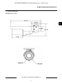
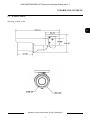
Dimensions (mm) 90 (Ø) x 280 (L)
Weight 0.95 kg
Enclosure Aluminium, white, mounting bracket and sunshield in-set included
Power Supply PoE, 12VDC, 24 VAC
Power Consumption 7 W, 10 W (IR on), 12 W (heater on), 15 W (heater and IR on)
Operating Temperature -40°C ~ 50°C
Built-in Heater Yes
Degree of Protection IP 66

NVIP-8DN7560H/IRH-2P User’s manual ver.1.1 (short form)
All rights reserved © AAT Holding S.A.
7
FOREWORD INFORMATION
1.3. Camera dimensions
All dimensions in mm

NVIP-8DN7560H/IRH-2P User’s manual ver.1.1 (short form)
All rights reserved © AAT Holding S.A.
8
1.4. Package contents
After you open the package make sure that the following elements are inside:
IP camera
230 VAC / 12 VDC power supply
Accessories bag
Short version of user’s manual
CD containing manual and software
If any of this elements has been damaged during transport, pack all the elements back into the original
box and contact your supplier for further assistance.
CAUTION!
If the device was brought from a location with lower temperature, please wait until it reaches the
temperature of location it is currently in. Turning the device on immediately after bringing it
from a location with lower ambient temperature is forbidden, as the condensing water vapour
may cause short-circuits and damage the device as a result.
Before starting the device familiarize yourself with the description and the role of particular
inputs, outputs and adjusting elements that the device is equipped with.
1.4. Package contents
After you open the package make sure that the following elements are inside:
IP camera
Accessories bag
Short version of user’s manual
If any of this elements has been damaged during transport, pack all the elements back into the original
box and contact your supplier for further assistance.
CAUTION!
If the device was brought from a location with lower temperature, please wait until it reaches the
temperature of location it is currently in. Turning the device on immediately after bringing it
from a location with lower ambient temperature is forbidden, as the condensing water vapour
may cause short-circuits and damage the device as a result.
Before starting the device familiarize yourself with the description and the role of particular
inputs, outputs and adjusting elements that the device is equipped with.
FOREWORD INFORMATION

NVIP-8DN7560H/IRH-2P User’s manual ver.1.1 (short form)
All rights reserved © AAT Holding S.A.
9
2. START-UP AND INITIAL IP CAMERA CONFIGURATION
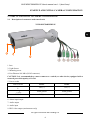
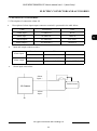
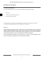
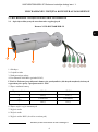
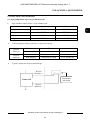
2.1. Description of connectors and control tools
NVIP-8DN7560H/IRH-2P
1 Lens
2. Light Sensor
3. Mounting screw
4. Port Ethernet 100 Mb/s (RJ-45 connector)
CAUTION! It is recommended to connect camera to a switch (or other device) equipped with a
network port with capacity of 1 Gb/s
5. Power socket
6. Alarm input/output
7. Audio output
8. Audio input
9. BNC video output (maintenance only)
START-UP AND INITIAL CAMERA CONFIGURATION
Power socket
24VAC 12VDC
+
24V(+) 12V(+)
Earth ground Earth ground
─ 24V(-) 12V(-)
2
3
1

NVIP-8DN7560H/IRH-2P User’s manual ver.1.1 (short form)
All rights reserved © AAT Holding S.A.
10
2.2. Connecting power supply to the camera.
The camera can be supplied by using RJ45 network socket. To run NOVUS IP camera you have to
connect Ethernet cable between camera and network switch with PoE support (IEEE 802.3at). You can
also use a power injector compatible with IEEE 802.3at standard. Camera can be also supplied by using
power supply adapter compatible with camera parameters (description of the power connector is placed
in the 2.1 Chapter of this user’s manual).
Information:
Power supply adapter is not included. Please use power adapter with parameters specified in user’s
manual.
CAUTION!
In order to provide protection against voltage surges/lightning strikes, usage of appropriate surge
protectors is advised. Any damages resulting from surges are not eligible for service repairs.
CAUTION!
It is forbidden to use as the camera power source PoE equipment (adapters, etc.) not compatible
with IEEE 802.3af standard (items called “passive PoE power supply”). Damages that results
from the usage of improper power supply source are not covered by the warranty.
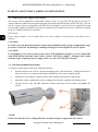
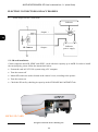
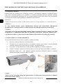
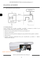
2.3. NVIP-8DN7560H/IRH-2P mounting
To mount a camera please follow the instructions below:
Put the bracket to the wall in a desired mounting place (with cable hole). Taking the bracket’s
base screw holes as a pattern, mark future drilling holes for screws using a punch.
Drill holes in accordance with previously done markings and base hole placement.
Mount the camera with bracket on the ceiling/wall with three supplied self tapping screws.
Unscrew Screws „A” and „B” adjust the location and angle of the camera, and tighten the
screws.
NOTE:
Please note that the wall or ceiling must have enough strength to support the IP Camera.
START-UP AND INITIAL CAMERA CONFIGURATION
A
A
B

NVIP-8DN7560H/IRH-2P User’s manual ver.1.1 (short form)
All rights reserved © AAT Holding S.A.
11
CAUTION!
In order to obtain declared degree of protection please seal the camera base to prevent water
getting inside. Furthermore, when installing the camera on rough/uneven surfaces, please
additionally seal the junction with appropriate sealing mass. Please pay special attention to any
mounting holes and if they are a loop-through ones, seal them too.
CAUTION!
The declared degree of protection of the camera relates to its housing and does not take into
account the possibility of moisture infiltration into the interior of the camera by camera
connectors / connecting cables. Camera connectors / connection cables protection through i.e.
sealing up is the responsibility of the camera installer. The manufacturer is not liable for any
damages to the camera caused as a result of failing in performing that activity by installer, which
also means that camera damaged in that way is not subject to warranty repairs.
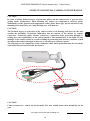
The following are the components of the connection cable which protection must be necessarily
ensured by the person who installs the camera:
CAUTION!
Camera connectors / sockets are not hermetic. The user should ensure their hermiticity on his
own.
START-UP AND INITIAL CAMERA CONFIGURATION

NVIP-8DN7560H/IRH-2P User’s manual ver.1.1 (short form)
All rights reserved © AAT Holding S.A.
12
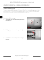
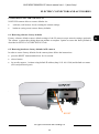
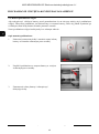
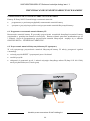
2.4. Desiccant mounting guide
To prevent moisture from condensing on IP Camera’s Glass Cover, we strongly suggest you to place
the desiccant in the IP Camera before installing and replace a new one every time when opening the
Front Cover. New moisture absorbers should be purchased on their own.
Description of desiccant usage:
1. Unscrew the screw on Camera Housing and remove
the Front Cover
2. Firmly place the desiccant on the spot as the figures
on the right side.
3. Install the Front Cover back in position and tighten
the screw.
START-UP AND INITIAL CAMERA CONFIGURATION

NVIP-8DN7560H/IRH-2P User’s manual ver.1.1 (short form)
All rights reserved © AAT Holding S.A.
13
2.4. Starting the IP camera
To run NOVUS IP camera you have to connect ethernet cable between camera and network switch.
To power it up you can connect it directly via power supply adapter with parameters compatible with
camera power supply specification. NVIP-8DN7560H/IRH-2P can be powered with PoE (IEEE
802.3at ) compatible switch.
After connecting power supply green LED should light on. Initialization process is then started which
takes about 30 seconds. You can then proceed to connect to the camera via web browser.
If the connection is successfully established orange LED blinks with a frequency proportional to the
quantity of data sent. Connecting via web browser is then possible. If connection isn’t established (the
network cable is disconnected) green and orange LEDs aren't active, solid light means that network
connection is ok but camera doesn't receive or send any data, with possible PC network settings error.
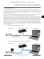
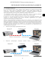
The recommended way to start an IP camera and perform its configuration is a connection directly
to the network switch which is not connected to other devices. To obtain further information about
network configuration parameters (IP address, gateway, network mask, etc.) please contact your
network administrator.
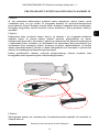
Connection utilising network switch with PoE
Connection utilising external power supply and network switch
START-UP AND INITIAL CAMERA CONFIGURATION
IP Camera
Network transmission
Network Switch
Computer
Network transmission
Power supply and
network transmission
Computer
IP Camera
Network Switch PoE
Network transmission

NVIP-8DN7560H/IRH-2P User’s manual ver.1.1 (short form)
All rights reserved © AAT Holding S.A.
14
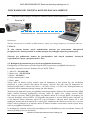
Connection utilising external power supply directly to the computer
Information:
Power supply adapter is not included. Please use power adapter with parameters specified in user ‘s
manual.
Caution:
In order to provide protection against voltage surges/lightning strikes, usage of appropriate surge
protectors is advised. Any damages resulting from surges are not eligible for service repairs.
It is recommended to connect camera to a switch (or other device) equipped with a network port
with capacity of 1 Gb/s
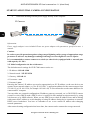
2.5. Initial configuration via the web browser
The default network settings for NVIP-7000 camera series are :
1. IP address= 192.168.1.200
2. Network mask - 255.255.255.0
3. Gateway - 192.168.1.1
4. User name - root
5. Password - pass
Knowing the camera’s IP address you need to appropriately set PC IP address, so the two devices can
operate in one network subnet ( e.g. for IP 192.168.1.1, appropriate address for the camera ranges from
192.168.1.2 to 192.168.1.254, for example 192.168.1.60). It is not allowed to set the same addresses for
camera and PC computer
You can either set a network configuration (IP address, gateway, net mask, etc.) of NOVUS IP camera
yourself or select DHCP mode (DHCP server is required in this method in target network) by using
web browser or by NMS software. When you use DHCP server check IP address lease and its linking
with camera MAC address to avoid changing or losing IP address during device operation or network/
DHCP server breakdown. You have to remember to use a new camera IP address after changing
network parameters.
After network setting configuration has been done, the camera can be connected to a target network.
START-UP AND INITIAL CAMERA CONFIGURATION
IP Camera
Network transmission - cross over cable
Computer

NVIP-8DN7560H/IRH-2P User’s manual ver.1.1 (short form)
All rights reserved © AAT Holding S.A.
15
3. NETWORK CONNECTION UTILIZING WEB BROSWER
3.1. Recommended PC specification for web browser connections
Requirements below apply to connection with an IP camera, assuming smooth image display
in 1920x1080 resolution and 25 fps speed.
1. CPU Intel Core TM i5-2430M 2,4 GHz or newer
2. RAM Memory min. 2 GB
3. VGA card (any displaying Direct 3D with min. 128 MB RAM memory)
4. OS Windows XP / VISTA/ Windows 7/ Windows 8
5. Direct X version 9.0 or newer
6. Network card 1000 Mb/s
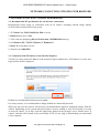
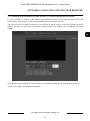
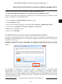
3.2. Connection with IP camera via the Internet Explorer
You have to enter camera IP address in the Internet Explorer address bar. If IP address is correct user
login window will be displayed:
Default user is root and default password is pass.
For safety reasons, it is recommended to change default user name and password.
When you log on to the camera, web browser will download the applet for displaying images from the
camera. Depending on the current Internet Explorer security settings it may be necessary to accept
an ActiveX control. To do this, click the right mouse button on the message, select "Install Active X
control" and then click Install. After successfully NVIP Viewer plug in downloading run and install
it on a computer.
NETWORK CONNECTION UTILIZING WEB BROWSER

NVIP-8DN7560H/IRH-2P User’s manual ver.1.1 (short form)
All rights reserved © AAT Holding S.A.
16
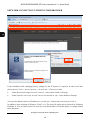
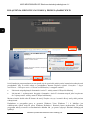
If the installation fails, changing security settings for the IE browser is required. In order to do that,
please choose: Tools > Internet options > Security tab > Custom level and:
Under Download unsigned ActiveX controls - select either Enable or Prompt
Under Initialize and script ActiveX controls not marked as safe - select Enable or Prompt
You can also add the camera’s IP address to “trusted zone” and set lowest security level for it.
In addition, when working in Windows Vista/7 or 8. The ActiveX applet may be blocked by Windows
Defender or User account control. In such case you should allow to run this applet, or simply disable
these functions.
NETWORK CONNECTION UTILIZING WEB BROWSER

NVIP-8DN7560H/IRH-2P User’s manual ver.1.1 (short form)
All rights reserved © AAT Holding S.A.
17
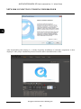
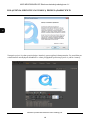
3.3. Connection with IP camera via other browser eg. Chrome, Mozilla Firefox, Safari )
It is also possible to connect to the camera using Mozilla Firefox, but this browser doesn't offer full
functionality of the camera, so the recommended browser is Internet Explorer.
The first run of the IP camera in browser is very similar to the IE version. After you type the correct IP
address you have to write correct username and password. The default user is root and password
is pass.
Next, blank screen is displayed. Then you have to install the missing Quick Time plug-in from site:
http://www.apple.com/quicktime/download/
NETWORK CONNECTION UTILIZING WEB BROWSER

NVIP-8DN7560H/IRH-2P User’s manual ver.1.1 (short form)
All rights reserved © AAT Holding S.A.
18
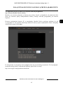
After downloading and running it, a window depicting installation of particular components is then
displayed. After proper installation pictures from the camera should become visible
NETWORK CONNECTION UTILIZING WEB BROWSER

NVIP-8DN7560H/IRH-2P User’s manual ver.1.1 (short form)
All rights reserved © AAT Holding S.A.
19
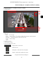
4. WWW INTERFACE - WORKING WITH IP CAMERA
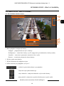
4.1. Displaying live
1. Main tabs
Home — live view page
System — camera settings ( IP, recording, sending alarm messages, motion detection)
Streaming — streaming settings for audio and video audio
Camera — picture settings
Logout
2. Language selection.
3. Video stream selection.
4. ActiveX settings for live video.
WWW INTERFACE - WORKING WITH IP CAMERA
- Display mode in web browser
- Full screen view
- Microphone - enable audio from microphone
- Speaker - enable audio sending to the camera
2
1
3
6
5
4

NVIP-8DN7560H/IRH-2P User’s manual ver.1.1 (short form)
All rights reserved © AAT Holding S.A.
20
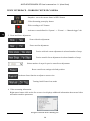
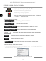
5. Zoom and focus adjustment.
6. Video streaming information.
Right mouse button click on the live screen view displays additional information about actual video
and audio transition parameters.
- Snapshot - saves the current frame in JPEG format
- Video Streaming pause/play button
- Web recording to AVI button
- Activates events defined in “System“ -> “Events“ -> “Manual trigger” tab
WWW INTERFACE - WORKING WITH IP CAMERA
Zoom wide/tele adjustment
Focus near/far adjustment
Precise wide/tele zoom adjustment in selected number of steps
Precise near/far focus adjustment in selected number of steps
Selects number of steps for precise zoom/focus adjustment
Reset zoom/focus settings to default position
Push auto-focus function to adjust to current view
Turning On/Off auto-focus mode
Strona się ładuje...
Strona się ładuje...
Strona się ładuje...
Strona się ładuje...
Strona się ładuje...
Strona się ładuje...
Strona się ładuje...
Strona się ładuje...
Strona się ładuje...
Strona się ładuje...
Strona się ładuje...
Strona się ładuje...
Strona się ładuje...
Strona się ładuje...
Strona się ładuje...
Strona się ładuje...
Strona się ładuje...
Strona się ładuje...
Strona się ładuje...
Strona się ładuje...
Strona się ładuje...
Strona się ładuje...
Strona się ładuje...
Strona się ładuje...
Strona się ładuje...
Strona się ładuje...
Strona się ładuje...
Strona się ładuje...
-
 1
1
-
 2
2
-
 3
3
-
 4
4
-
 5
5
-
 6
6
-
 7
7
-
 8
8
-
 9
9
-
 10
10
-
 11
11
-
 12
12
-
 13
13
-
 14
14
-
 15
15
-
 16
16
-
 17
17
-
 18
18
-
 19
19
-
 20
20
-
 21
21
-
 22
22
-
 23
23
-
 24
24
-
 25
25
-
 26
26
-
 27
27
-
 28
28
-
 29
29
-
 30
30
-
 31
31
-
 32
32
-
 33
33
-
 34
34
-
 35
35
-
 36
36
-
 37
37
-
 38
38
-
 39
39
-
 40
40
-
 41
41
-
 42
42
-
 43
43
-
 44
44
-
 45
45
-
 46
46
-
 47
47
-
 48
48


AAT NVIP-8DN7560H/IRH-2P Instrukcja obsługi
- Kategoria
- Kamery ochrony
- Typ
- Instrukcja obsługi
w innych językach
- English: AAT NVIP-8DN7560H/IRH-2P User manual
Powiązane artykuły
-
Novus NVIP-8DN7560V/IRH-2P Instrukcja obsługi
-
-
-
-
-
-
-
-
-