
ELiS AX air curtain
Kurtyna powietrzna ELiS AX
ELIS AX W-100
ELIS AX W-150
ELIS AX W-200
ELIS AX W-250
Technical documentation·Instruction manual
Dokumentacja techniczna·Instrukcja użytkowania
Quiet EC fans
High performance
A wide range of heating power
Works discreetly for you
Ciche wentylatory EC
Wysoka wydajność
Szeroki zakres mocy grzewczych

2 58948_MT-DTR-ELIS-AX-EN-PL-V2.13
TECHNICAL DOCUMENTATION EN ...... 3
1. IMPORTANT INFORMATION ............................................................................................................................................... 3
2. GENERAL INFORMATION .................................................................................................................................................... 4
3. TECHNICAL DATA ELIS AX ................................................................................................................................................... 5
4. DIMENSIONS ...................................................................................................................................................................... 6
5. INSTALLATION .................................................................................................................................................................... 6
6. HORIZONTAL INSTALLATION .............................................................................................................................................. 7
7. VERTICAL INSTALLATION .................................................................................................................................................... 8
8. CONNECTION OF ELECTRICAL INSTALALTION ................................................................................................................... 10
9. CONNECTION OF COMPONENTS ...................................................................................................................................... 12
10. CONNECTION OF HYDRAULIC INSTALLATION ................................................................................................................... 15
11. PARAMETERS OF THE HEATING MEDIUM......................................................................................................................... 16
12. OPERATION ...................................................................................................................................................................... 16
13. CLEANING AND MAINTENANCE........................................................................................................................................ 16
14. FILTER INSTALATION ........................................................................................................................................................ 17
15. CONFORMITY WITH WEEE DIRECTIVE 2012/19/UE .......................................................................................................... 18
16. SERVICE AND WARRANTY TERMS .................................................................................................................................... 18
DOKUMENTACJA TECHNICZNA PL ..... 19
1. WAŻNE INFORMACJE ....................................................................................................................................................... 19
2. INFORMACJE OGÓLNE ...................................................................................................................................................... 20
3. DANE TECHNICZNE KURTYN ELIS AX ................................................................................................................................. 21
4. WYMIARY ........................................................................................................................................................................ 22
5. MONTAŻ .......................................................................................................................................................................... 22
6. MONTAŻ POZIOMY .......................................................................................................................................................... 23
7. MONTAŻ PIONOWY ......................................................................................................................................................... 24
8. PODŁĄCZENIE INSTALACJI ELEKTRYCZNEJ......................................................................................................................... 26
9. PODŁĄCZENIE KOMPONENTÓW ....................................................................................................................................... 28
10. PODŁĄCZENIE INSTALACJI HYDRAULICZNEJ ...................................................................................................................... 31
11. PARAMETRY CZYNNIKA GRZEWCZEGO............................................................................................................................. 32
12. EKSPLOATACJA ................................................................................................................................................................. 32
13. CZYSZCZENIE I KONSERWACJA ......................................................................................................................................... 32
14. MONTAŻ FILTRA ............................................................................................................................................................... 33
15. ZGODNOŚĆ Z DYREKTYWĄ WEEE 2012/19/UE ................................................................................................................. 34
16. WARUNKI SERWISU I GWARANCJI ................................................................................................................................... 34

58948_MT-DTR-ELIS-AX-EN-PL-V2.13 3
TECHNICAL DOCUMENTATION EN
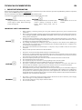
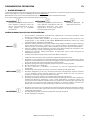
1. IMPORTANT INFORMATION
We have made every effort to make this manual as easy to understand as possible. However, if you have any difficulties, problems or questions,
please contact FLOWAIR support at: info@flowair.pl.
Also visit our website www.flowair.pl where you will find mounting tips.
In this manual you will find important safety information and tips marked as below:
WARNING
Dangerous practices which may result in
serious injury or death. Read all warnings
before starting work.
CAUTION
Unsafe practices which, if not avoided, may
result in damage to property or minor
injuries. Before starting work, read all
cautions.
ADVICE
Useful tips for the user and
installer.
IMPORTANT SAFETY INFORMATION:
ADVICE
1. Before installing, connecting, starting up, using and maintaining the device, please read this manual
completely.
2. After receiving the product, check that it has not been damaged during transport. If the product appears
to be damaged, DO NOT START TO MOUNT THE DEVICE; instead, you must immediately report the
damage to the delivery man.
3. The device must be mounted in a stable way and in accordance with the instructions, in a place that can
be easily accessed, thus ensuring the possibility of carrying out repairs and routine maintenance, as well
as allowing easy and safe disassembly of the device.
4. The stability and durability of installation of the device depends on the structure of the building (in
particular walls and ceilings). The person performing the assembly should take these conditions into
account when mounting the device.
5. The technical documentation should be kept in a safe place, easily accessible to the user and service
technician.
6. Always test the operation of the device after installation.
CAUTION
1. The power connection shall be performed only by an authorized person.
2. The device is not equipped with a thermostat that controls the room temperature. Do not use the device
in small rooms where there are people who are not able to leave the premises alone. Above mentioned
does not apply to rooms with constant supervision.
3. The device requires periodic inspections in accordance with the instructions in this manual.
4. Do not hang/put pressure on the device.
5. Do not place any objects on the device or hang anything on the connection stubs.
6. The product should be stored and assembled out of the reach of small children.
7. The device is dedicated to work indoors with a maximum air dustiness of 0.3 g/m3. The device has
elements made of aluminum, copper and steel and cannot be used in an corrosive environment.
8. Equipment cannot be used in an environment where oil mist is present.
9. This equipment may be used by children that are at least 8 years old, by persons with reduced physical
and mental abilities and persons with no experience and knowledge of the equipment, on condition that
the supervision or instruction regarding correct use of the equipment in a safe manner is provided and
the possible threats are understood. The device cannot be used by children to play. Unattended children
should not clean or maintain the equipment.
WARNING
1. The device is powered by dangerous voltage. Always disconnect the device from the power supply
before servicing or accessing its internal components.
2. Do not insert your fingers or any objects inside the device.
3. Do not cover the device.

4 58948_MT-DTR-ELIS-AX-EN-PL-V2.13
2. GENERAL INFORMATION
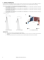
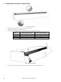
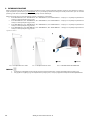
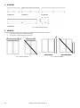
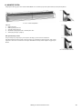
ELiS AX air curtain is a high-quality device that, by creating an air barrier, reduces heat losses. The device is dedicated ONLY for indoor use.
The ELiS AX air curtain is intended for horizontal installation above a door opening or vertical installation with a door opening.
The air curtain is available in a version with a water 3-row or 4-row heat exchanger:
• ELiS AX36-W3R-100, ELiS AX36-W3R-150, ELiS AX36-W3R-200, ELiS AX36-W3R-250 – air curtains with 3-row water heat exchanger
with a maximum range of 3,6 m*,
• ELiS AX36-W4R-100, ELiS AX36-W4R-150, ELiS AX36-W4R-200, ELiS AX36-W4R-250 – air curtains with 4-row water heat exchanger
with a maximum range of 3,6 m*,
• ELiS AX45-W3R-100, ELiS AX45-W3R-150, ELiS AX45-W3R-200, ELiS AX45-W3R-250 – air curtains with 3-row water heat exchanger
with a maximum range of 4,5 m*,
• ELiS AX45-W4R-100, ELiS AX45-W4R-150, ELiS AX45-W4R-200, ELiS AX45-W4R-250 – air curtains with 4-row water heat exchanger
with a maximum range of 4,5 m*.
* according to ISO 27327-1
❶
ADVICE
1. The use of an air curtain is recommended for public buildings .
2. Underpressure in the building significantly reduces the efficiency of the air barrier, the ventilation system should be
balanced.
3. At a wind speed of more than 3 m/s, the heated version of air curtain should be used to increase user comfort.
4,5 m
3,6 m
PIC. 2.1 ELIS AX45 RANGE.
PIC. 2.2 ELIS AX36 RANGE.
PIC. 2.3 DIRECTION OF AIR FLOW.
❶INLET ❷OUTLET

58948_MT-DTR-ELIS-AX-EN-PL-V2.13 5
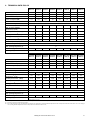
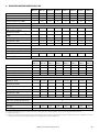
3. TECHNICAL DATA ELIS AX
ELiS AX36-
W3R-100
ELiS AX36-
W3R-150
ELiS AX36-
W3R-200
ELiS AX36-
W3R-250
ELiS AX36-
W4R-100
ELiS AX36-
W4R-150
ELiS AX36-
W4R-200
ELiS AX36-
W4R-250
Number of fans 2 3 5 6 2 3 5 6
Power supply [V/Hz] 230/50 230/50 230/50 230/50 230/50 230/50 230/50 230/50
Max. current consumption [A]
2,3
3,3
5,6
6,4
2,2
3,2
5,5
6,3
Power consumption [kW] 0,27 0,40 0,67 0,81 0,27 0,40 0,67 0,81
IP
21
Connection stub [''] 3/4
Air volume(1) [m3/h] 900 - 1800 1200-2700 2000-4300 2300-5300 800-1700 1100-2600 1900-4200 2200-5200
Max. air volume with filter
(Coarse 30%)
(1)
[m
3
/h]
1600 2400 3900 4800 1500 2300 3800 4700
Acoustic pressure level(2) [dB(A)] 42-60 43-61 45-63 46-64 41-59 42-60 44-62 45-63
Acoustic power level(3) [dB(A)] 58-76 59-77 61-79 62-80 57-75 58-76 60-78 61-79
Heating power (4) [kW] 8,1-12,9 11,8-20,5 17,1-29,0 21,4-38,0 8,7-15,2 12,7-24,1 20,6-36,7 24,7-46,6
Temperature increase (4) (ΔT ) [°C] 26-21 29-22 25-20 27-21 32-26 34-27 31-26 33-26
Max. Water pressure [MPa] 1,6
Max. water temperature [˚C] 60
Max. operating temperature [˚C] 50
Device mass [kg] 38,5 53,3 71,7 86,8 40,0 55,6 74,8 90,3
Max. range(1) [m] 3,6
(1) According to ISO 27327-1 (airflow given for fan setting range 25%-100%);
(2) Acoustic pressure level has been measured in a 1500m3 space with a medium sound absorption coefficient, directional factor: Q=2;
(3) Acoustic power level according to ISO 27327-2;
(4) Power and temperature range specified for the parameters fan setting of 25%,, heating medium temperature 60/40°C temperature at the inlet to the device 18°C - fan setting of
100%, heating medium temperature 60/40°C temperature at the inlet to the device 18°C;
ELiS AX45-
W3R-100
ELiS AX45-
W3R-150
ELiS AX45-
W3R-200
ELiS AX45-
W3R-250
ELiS AX45-
W4R-100
ELiS AX45-
W4R-150
ELiS AX45-
W4R-200
ELiS AX45-
W4R-250
Number of fans
3 4 6 7 3 4 6 7
Power supply [V/Hz]
230/50 230/50 230/50 230/50 230/50 230/50 230/50 230/50
Max. current consumption [A] 3,3 4,6 6,4 7,6 3,2 4,5 6,3 7,5
Power consumption [kW]
0,49
0,65
0,99
1,15
0,49
0,65
0,99
1,15
IP 21
Connection stub ['']
3/4
Air volume(1) [m3/h] 1100-2500 1500-3500 2200-5000 2400-6100 1000-2400 1400-3400 2100-4900 2300-6000
Max. air volume with filter
(Coarse 30%)
(1)
[m
3
/h]
2300 3200 4500 5500 2200 3100 4400 5400
Acoustic pressure level(2) [dB(A)] 43-61 44-62 45-64 46-65 42-60 43-61 44-63 45-64
Acoustic power level(3) [dB(A)] 59-77 60-78 61-80 62-81 58-76 59-77 60-79 61-80
Heating power (4) [kW] 9,3-15,7 13,9-24,1 18,4-31,8 22,1-41,4 10,3-19,1 15,3-28,9 22,2-40,6 25,6-51,3
Temperature increase (4) (ΔT ) [°C] 25-18 27-20 24-19 27-20 30-23 32-25 31-24 33-25
Max. water pressure [MPa] 1,6
Max. water temperature [˚C] 60
Max. operating temperature [˚C] 50
Device mass [kg] 40,8 55,5 73,7 88,8 42,3 57,8 76,8 92,3
Max. range(1) [m] 4,5

6 58948_MT-DTR-ELIS-AX-EN-PL-V2.13
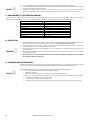
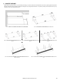
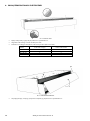
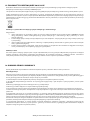
4. DIMENSIONS
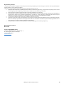
5. INSTALLATION
Air curtains must be installed as close as possible to the door opening and cover:
• the entire width (applies to horizontal installation),
• full height (applies to vertical mounting).
CORRECT
WRONG
CORRECT
WRONG
PIC. 4.1 BASIC DIMENSIONS.
PIC. 5.1 HORIZONTAL INSTALLATION.
PIC. 5.2 VERTICAL INSTALLATION.

58948_MT-DTR-ELIS-AX-EN-PL-V2.13 7
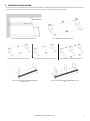
6. HORIZONTAL INSTALLATION
ELiS AX curtains are adapted for horizontal installation, with the use of dedicated brackets or M8 threaded rods.
During assembly, keep the
minimum distances as shown in the figure below. The device must be leveled before it is put into operation.
min. 100 mm
PIC. 6.1 MOUNTING WITH DEDICATED BRACKETS.
PIC. 6.2 BRACKETS DISTANCE ELIS AX W 100.
PIC. 6.3 BRACKETS DISTANCE ELIS AX W 150.
PIC. 6.4 BRACKETS DISTANCE ELIS AX W 200.
PIC. 6.5 BRACKETS DISTANCE ELIS AX W 250.
PIC. 6.6 INSTALLATION WITH THREADED RODS ELIS
AX 100/150/200.
PIC. 6.7 INSTALLATION WITH THREADED RODS ELIS AX
250.

8 58948_MT-DTR-ELIS-AX-EN-PL-V2.13
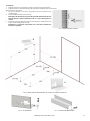
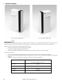
7. VERTICAL INSTALLATION
CAUTION
In the case of vertical installation of the air curtain and when the water connection is located in the lower part of the device (PIC. 7.1), it
may be difficult to vent the water heat exchanger. Before turning the device on, check that the water heat exchanger has been filled with
water and vented.
The ELiS AX vertical air curtain mounting kit includes:
• mounting base (A) for mounting the air curtain to the floor,
• side bracket (B) for mounting the curtain to the wall,
• M8 metric screws with washers for mounting the curtain to the base and side bracket (4 pieces).
During installation, you should:
• Fix the base (A) at a distance of not less than 50 mm and not more than 100 mm from the wall where the door is.
• Fix the side bracket (B) at a d
• W przypadku montażu pionowego kurtyny i dolnego przyłącza wody, odpowietrzenie wymiennika wodnego może być
utrudnion
e. Przed uruchomieniem urządzenia należy sprawdzić, czy wymiennik wodny został napełniony wodą i
odpowietrzony. istance of not less than 100 mm from the wall on which the thread rods will be placed.
•
The height of attachment of the side bracket to the wall depends on the model of the device.
Device model Height of holes for threaded rods
(letter H in the diagram below)
ELiS AX 100 854 mm
ELiS AX 150 1100 mm
ELiS AX 200 1854 mm
ELiS AX 250 2354 mm
PIC. 7.1. ON THE LEFT SIDE OF THE DOOR.
PIC. 7.2. ON THE RIGHT SIDE OF THE DOOR.

58948_MT-DTR-ELIS-AX-EN-PL-V2.13 9
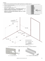
Instructions:
1. Drill holes for the base keeping the distances shown in the diagram below.
2. Drill holes for the side bracket, keeping the appropriate height for your model of unit.
Attach the base to the floor.
3. Fix the side bracket to the device using M8 screws (not included in the
installation kit).
4. Fasten the M8 threaded rods in the wall.
Remember, the threaded rods protruding from the wall must be shorter
than the distance of the unit from the wall, so as not to damage the air
curtain.
5. Mount the unit by screwing it to the base using washers and M8 screws and
to the rods protruding from the wall.
Remember to counter the side bracket (use a nut before and after the
bracket (see graphic).
B
A
PIC. 7.3. COUNTER ON WALL BRACKET.
PIC. 7.4. SCHEME FOR THE MOUNTING HOLES OF THE BASE (A) AND WALL BRACKET (B).
PIC. 7.5. THE BASE HEIGHT
PIC. 7.6. THE WIDTH OF WALL BRACKET

10 58948_MT-DTR-ELIS-AX-EN-PL-V2.13
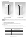
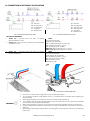
8. CONNECTION OF ELECTRICAL INSTALALTION
• Remove screws from down and above as in the picture PIC. 8.1
• Use imbus 3.0 mm key to remove the screws.
• Depending on the length of the device, the number of screws varies (see the table).
Model Number of bolts from above Number of bolts from below
ELIS AX 100
1
3
ELIS AX 150
2
4
ELIS AX 200
2
5
ELIS AX 250
3
6
•
To remove the cover, tilt it (1) and slide it out of the catches (2) as shown in the graphic PIC. 8.2
1
2
2
PIC. 8.1 SCREW POSITIONS.
PIC. 8.2 REMOVING THE COVER.

58948_MT-DTR-ELIS-AX-EN-PL-V2.13 11
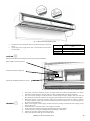
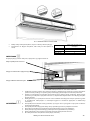
• Unscrew the screws inside the device to be able to open the inspection
hatch.
• Depending on the length of the device, the number of screws varies
(see the table).
Model
Number of screws to unscrew
inside
ELIS AX 100
3
ELIS AX 150
5
ELIS AX 200
5
ELIS AX 250
7
CAUTION
Hold the hatch while unscrewing to prevent it from opening suddenly.
Power supply conection position
Transformer position (optional)
Position of the DRV ELIS AX in the curtain
WARNING
1. The power connection should be made in accordance with the technical documentation. The device
installation should always be carried out in accordance with applicable local safety standards.
2. The cross-section and type of cable should be selected by the designer. Always make sure that the
disconnectors and protective switches are properly sized and disconnect all poles of the power supply.
3. Make sure that the connection of power supply and controllers to the ELiS AX curtain is made in
accordance with the electrical specifications and the instructions included in the connection diagrams in
the technical documentation.
4. Before connecting the power supply, check that the mains voltage corresponds to the voltage on the
device's type plate.
5. Check the power connection before connecting the air curtain.
6. Starting the device without connecting the grounding wire is not allowed.
7. Protect the power cord against pulling out by clamping the cable gland.
8. Tighten all connection cables in the block properly
9. Do not start the device with the service hatch open.
PIC. 8.3 RELEASING THE INSPECTION HATCH.
PIC. 8.4 VIEW OF CONNECTIONS AND DRV ELIS AX INSIDE THE INSPECTION HATCH.

12 58948_MT-DTR-ELIS-AX-EN-PL-V2.13
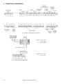
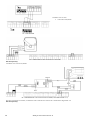
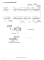
9. CONNECTION OF COMPONENTS
Conductor cross-section:
• min. 3x1,5 mm2
• Protection B10
Conductor cross-section:
• min. 2x0,5 mm2
PIC. 9.1 GENERAL APPEARANCE OF THE DRV ELIX EC.
PIC. 9.2 POWER SUPPLY.
PIC. 9.3 CONNECTING OF THE DOOR SENSOR.

58948_MT-DTR-ELIS-AX-EN-PL-V2.13 13
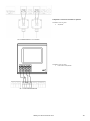
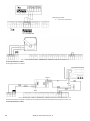
Temperature sensors PT1 and PT4 are optional.
Conductor cross-section:
• 2x0,5mm2
Conductor cross-section:
• LIYY-P min. 2x2x0,5mm2
PIC. 9.4 CONNECTION OF PT-1000 SENSORS.
PIC. 9.5 T-BOX ZONE CONNECTION.

14 58948_MT-DTR-ELIS-AX-EN-PL-V2.13
Conductor cross-section:
• LIYY-P min. 2x2x0,5mm2
Kit sold separately.
Conductor cross-section: 3x0,75mm2
The valve set includes an actuator, a transformer and a set of wires for connection as shown in the diagram PIC. 9.8.
Kit sold separately.
PIC. 9.6 DRV CHAINING.
PIC. 9.8 CONNECTION OF 2-WAY VALVE WITH AN ACTUATOR (FLUENT MODULATION 0-10 V).
PIC. 9.7 CONNECTION OF 3-WAY VALVE WITH A 3P ACTUATOR.

58948_MT-DTR-ELIS-AX-EN-PL-V2.13 15
10. CONNECTION OF HYDRAULIC INSTALLATION
SRX VALVES PARAMETERS:
SRX2d 3/4" – two-way valve 3/4" with an actuator
(fluent modulation 0-10 V).
SRX2d 1 1/4" – two-way valve 1 1/4" with an actuator (fluent
modulation 0-10 V).
SRX2d:
Class of protection: IP54,
Supply voltage: AC/DC 24 V,
(with a supplied transformer: 230 V), 50 Hz,
Max. medium temperature : +120°C,
Max. operating pressure: 2,5 MPa,
SRX2d 3/4": Water flow range: 220 – 1330 l/h,
SRX2d 1 1/4": Water flow range: 550 – 4001 l/h
SRX3d 3/4" – three-way valve 3/4" with an actuator
(3-point modulation)
SRX3d:
Class of protection: IP40,
Supply voltage: AC 230 V/50 Hz,
Max. medium temperature: +120°C,
Max. operating pressure: 1,0 MPa,
SRX3d 3/4" Kvs: 6,3 m3/h,
Running time: 140 s
WARNING
1. Disconnect the curtain power supply before connecting the water system.
2. The connection should be made without stress. It is recommended to use flexible ducts supplying the
heating medium.
3. Water supply should be connected to the connector marked with the symbol ↑ IN.
4. The installation with the heating medium must be protected against the increase of the heating medium
pressure above the permissible value (1.6 MPa).
5. Before starting the device, check the correct connection of the heating medium and the system for leaks.
6. During assembly of the installation it is absolutely necessary to immobilize the exchanger's connector pipes
(PIC. 10.3).
7. After filling the system with heating medium, check the tightness of the hydraulic connections, including the
built-in vent.
ZK – ball valve
ZO – bleeding valve
ZD – drainage valve
FS – mesh filter
KP – flexible hoses
ZK – ball valve
ZO – bleeding valve
ZR – balancing valve
ZD – drainage valve
FS – mesh filter
KP – flexible hoses
PIC. 10.1 CONNECTION EXAMPLE OF SRX2D.
PIC. 10.2 CONNECTION EXAMPLE OF SRX3D.
PIC. 10.3 COUNTER.
PIC. 10.4 WATER INLET CONNECTION POINT

16 58948_MT-DTR-ELIS-AX-EN-PL-V2.13
ADVICE
1. It is recommended to use bleeding/air release valves at the highest point of the installation.
2. In the event that the water from the device is drained for a longer period of time, the exchanger tubes should
be blown and dried with compressed air.
3. Installation should be carried out in such a way that in the event of a failure it is possible to dismantle the
device (use of flexible hoses is recommended). For this purpose, use shut-off valves next to the device.
11. PARAMETERS OF THE HEATING MEDIUM
The water heat exchanger can be supplied with water or glycol solutions up to 60% . The heat exchanger tubes are made of copper. The
heating medium should not cause corrosion of this material. In particular, the parameters as below should be provided.
Parameter
Value
pH
7,5-9,0
Pollution
Free of sediments/particles
Total hardness
[Ca2+,Mg2+]/ [HCO3-] > 0.5
Oil and grease
<1 mg/l
Oxygen
<0.1mg/l
HCOᵌ
60-300 mg/l
Ammonia
< 1.0 mg/l
Sulphides
< 0.05 mg/l
Chlorides, Cl
<100 mg/l
12. OPERATION
WARNING
1. The device must be periodically checked. These activities should be performed ONLY by qualified personnel.
If the device malfunctions, turn it OFF immediately and contact FLOWAIR SERVICE SUPPORT.
2. Do not attempt to repair, move, modify, or reinstall the device yourself. Performing these activities by
unauthorized personnel may result in electric shock or fire.
3. Do not use a damaged device. The manufacturer is not responsible for damages resulting from the use of a
damaged device.
4. The device is intended for indoor use at temperatures above 0°C. At temperatures below 0°C there is a risk of
freezing of the medium.
5. The manufacturer is not responsible for damage to the heat exchanger resulting from the freezing of
the medium in the heat exchanger.
13. CLEANING AND MAINTENANCE
ADVICE
Periodically check the dirt status of the heat exchanger (not less than once a year). Clogging a part of the air intake
causes a decrease in the heating power of the device and adversely affects the operation of the fans.
Cleaning the exchanger should be carried out in accordance with the following guidelines:
• The power supply must be disconnected during cleaning.
• Open the service flap.
• When cleaning the exchanger, be careful not to bend the aluminum fins.
• It is not recommended to use sharp objects for cleaning, due to the possibility of damage to the lamellas.
• Cleaning with compressed air is recommended.
• The exchanger cannot be cleaned with water!
•
Cleaning should be carried out along the slats, with the blowing nozzle perpendicular to exchanger.

58948_MT-DTR-ELIS-AX-EN-PL-V2.13 17
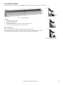
14. FILTER INSTALATION
ELiS AX air curtains can operate with a ISO COARSE 30% filter installed before the exchanger, inside the unit.
Assembly:
1. Disconnect the power supply.
1. Unscrew the cover PIC. 8.1.
2. Remove the cover PIC. 8.2.
3. Slide the filter between the exchanger and the housing PIC. 14.2.
4. Place the cover in original position and screw it back on.
Filter sold separately.
The filter is flexible and will adjust itself, locking on both sides of the device.
To remove/replace the filter, pull it out of the device by bending it slightly. The filter should be
replaced periodically depending on the degree of dirtiness. Always use original filters.
PIC. 14.1 FILTER IN THE DEVICE.
PIC. 14.2 FILTER INSTALLATION.

18 58948_MT-DTR-ELIS-AX-EN-PL-V2.13
15. CONFORMITY WITH WEEE DIRECTIVE 2012/19/UE
Running a business without harming the environment and observing the rules of proper handling of waste electrical and electronic
equipment is a priority for FLOWAIR.
The symbol of the crossed out wheeled bin placed on the equipment, packaging or documents attached means that the product must not
be disposed of with other wastes. It is the responsibility of the user to hand the used equipment to a designated collection point for proper
processing. The symbol means that the equipment was placed on the market after August 13, 2005.
For information regarding recycling of waste electrical and electronic equipment, please contact your local distributor.
R E M E M B E R:
Do not dispose of used equipment together with other waste! There are financial penalties for this. Proper handling of used equipment
prevents potential negative consequences for the environment and human health. At the same time, we save the Earth's natural resources,
reusing resources obtained from the processing of equipment.
16. SERVICE AND WARRANTY TERMS
Please contact your dealer in order to get familiar with the warranty terms and its limitation.
In the case of any irregularities in the device operation, please contact the manufacturer’s service department.
The manufacturer bears no responsibility for operating the device in a manner inconsistent with its purpose, by persons not
authorised for this, and for damage resulting from this!
Made in Poland
Made in EU
Manufacturer: FLOWAIR SP. Z O.O.
(formerly: FLOWAIR Głogowski i Brzeziński Sp. J.)
st. Chwaszczyńska 135, 81-571 Gdynia
e-mail: info@flowair.pl
www.flowair.com

58948_MT-DTR-ELIS-AX-EN-PL-V2.13 19
DOKUMENTACJA TECHNICZNA PL
1. WAŻNE INFORMACJE
Dołożyliśmy wszelkich starań, aby niniejsza instrukcja była jak najłatwiejsza do zrozumienia. Jeśli jednak masz jakieś trudności, problemy lub
pytania, skontaktuj się ze wsparciem FLOWAIR pod adresem: info@flowair.pl.
Odwiedź także naszą stronę internetową www.flowair.pl, na której znajdziesz pełne wskazówki montażowe.
W niniejszej instrukcji znajdziesz ważne wskazówki oznaczone jak poniżej:
OSTRZEŻENIE
Niebezpieczne praktyki, których zaistnienie
może skutkować poważnym urazem lub
śmiercią. Przed przystąpieniem do pracy
należy zapoznać się ze wszystkimi
ostrzeżeniami.
PRZESTROGA
Niebezpieczne praktyki, których zaistnienie
może skutkować uszkodzeniem dóbr lub
nieznacz
nymi obrażeniami ciała. Przed
przystąpieniem do pracy należy zapoznać
się ze wszystkimi przestrogami.
PORADA
Przydatne wskazówki dla
użytkownika i instalatora.
WAŻNE INFORMACJE DOTYCZĄCE BEZPIECZEŃSTWA:
PORADA
1. Przed montażem, podłączeniem, uruchomieniem, użytkowaniem i konserwacją urządzenia należy
zapoznać się w całości z niniejszą instrukcją.
2. Po odebraniu produktu należy sprawdzić, czy nie uległ on uszkodzeniu podczas transportu. Jeżeli
produkt wydaje się być uszkodzony, NIE NALEŻY ROZPOCZYNAĆ INSTALACJI; zamiast tego należy
natychmiast zgłosić uszkodzenie przewoźnikowi.
3. Urządzenie musi być zamontowane w sposób stabilny, trwały i zgodny z instrukcją, w miejscu, do którego
można uzyskać łatwy dostęp, zapewniając w ten sposób mo
żliwość przeprowadzania napraw i
rutynowych czynności konserwujących, a także umożliwiając łatwy i bezpieczny demontaż urządzenia.
4. Stabilność i trwałość montażu urządzenia jest zależna od konstrukcji budynku (w szczególności ścian
i stropów). Wykonując montaż, należy uwzględnić te uwarunkowania.
5.
Dokumentację techniczną należy przechowywać w bezpiecznym miejscu, łatwo dostępnym dla
użytkownika i serwisanta.
6. Po zakończeniu instalacji należy zawsze przetestować działanie urządzenia.
PRZESTROGA
1. Podłączenie zasilania powinna wykonać wyłącznie odpowiednio uprawniona osoba.
2. Urządzenie nie jest wyposażone w termostat kontrolujący temperaturę w pomieszczeniu. Nie używaj
urządzenia w małych pomieszczeniach, w których znajdują się osoby nie będące zdolne samodzielnie ich
opuścić. Nie dotyczy pomieszczeń z zapewnionym stałym nadzorem.
3. Urządzenie wymaga okresowych przeglądów, zgodnie z zapisami w niniejszej instrukcji.
4. Nie wolno zawieszać się na urządzeniu.
5.
Nie wolno umieszczać na urządzeniu, ani zawieszać na króćcach przyłączeniowych żadnych
przedmiotów.
6. Produkt należy przechowywać i montować w miejscach niedostępnych dla małych dzieci.
7. Urządzenie dedykowane jest do pracy wewnątrz pomieszczeń o maksymalnym zapyleniu powietrza
0,3 g/m3. Urządzenie posiada elementy wykonane z aluminium, miedzi oraz stali i nie może być
stosowane w środowisku mogącym powodować ich korozję.
8. Urządzenia nie mogą być stosowane w środowisku, gdzie występuje mgła olejowa.
9. Niniejszy sprzęt może być użytkowany przez dzieci w wieku co najmniej 8 lat i przez osoby o obniżonych
możliwościach fizycznych, umysłowych i osoby o braku doświadczenia i znajomości sprzętu, jeżeli
zapewniony zostanie nadzór lub instruktaż odnośnie do użytkowania sprzętu w bezpieczny sposób, tak
aby związane z tym zagrożenia były zrozumiałe. Urządzenie nie może być używane przez dzieci do
zabawy. Dzieci bez nadzoru nie powinny wykonywać czyszczenia i konserwacji sprzętu.
OSTRZEŻENIE
1. Urządzenie jest zasilane napięciem elektrycznym niebezpiecznym dla człowieka. Należy zawsze odłączyć
urządzenie od zasilania przed rozpoczęciem czynności serwisowych lub uzyskaniem dostępu do jego
podzespołów wewnętrznych
.
2. Nie należy wkładać palców ani żadnych przedmiotów do wnętrza urządzenia.
3. Nie wolno przykrywać urządzenia.

20 58948_MT-DTR-ELIS-AX-EN-PL-V2.13
2. INFORMACJE OGÓLNE
Kurtyna powietrzna ELiS AX jest wysokiej jakości urządzeniem, które poprzez nadmuch powietrza ogranicza straty związane z wymianą
ciepła. Urządzenie przeznaczone jest WYŁĄCZNIE do pracy wewnątrz pomieszczeń. Kurtyna ELiS AX przeznaczona jest do montażu
poziomego nad otworem drzwiowym lub pionowego przy otworze drzwiowym.
Kurtyna występuje w wersji z wymiennikiem wodnym 3-rzędowym i 4-rzędowym:
• ELiS AX36-W3R-100; ELiS AX36-W3R-150; ELiS AX36-W3R-200; ELiS AX36-W3R-250 – kurtyny z 3-rzędowym wymiennikiem
wodnym o maksymalnym zasięgu 3,6 m*,
• ELiS AX36-W4R-100; ELiS AX36-W4R-150; ELiS AX36-W4R-200; ELiS AX36-W4R-250 – kurtyny z 4-rzędowym wymiennikiem
wodnym o maksymalnym zasięgu 3,6 m*,
• ELiS AX45-W3R-100; ELiS AX45-W3R-150; ELiS AX45-W3R-200; ELiS AX45-W3R-250 – kurtyny z 3-rzędowym wymiennikiem
wodnym o maksymalnym zasięgu 4,5 m*,
• ELiS AX45-W4R-100; ELiS AX45-W4R-150; ELiS AX45-W4R-200; ELiS AX456-W4R-250 – kurtyny z 4-rzędowym wymiennikiem
wodnym o maksymalnym zasięgu 4,5 m*.
* zgodnie z ISO 27327-1
❶
PORADA
1. Podciśnienie w budynku znacznie obniża sprawność bariery powietrznej, należy zrównoważyć bilans wentylacyjny.
2. Przy prędkości napływającego do budynku wiatru powyżej 3 m/s, wersja z podgrzewem zwiększa komfort użytkowników.
4,5 m
3,6 m
❶WLOT ❷WYLOT
RYS. 2.2 ZASIĘG KURTYNY ELIS AX45.
RYS. 2.3 ZASIĘG KURTYNY ELIS AX36.
RYS. 2.1 KIERUNEK PRZEPŁYWU POWIETRZA.
Strona się ładuje...
Strona się ładuje...
Strona się ładuje...
Strona się ładuje...
Strona się ładuje...
Strona się ładuje...
Strona się ładuje...
Strona się ładuje...
Strona się ładuje...
Strona się ładuje...
Strona się ładuje...
Strona się ładuje...
Strona się ładuje...
Strona się ładuje...
Strona się ładuje...
Strona się ładuje...
-
 1
1
-
 2
2
-
 3
3
-
 4
4
-
 5
5
-
 6
6
-
 7
7
-
 8
8
-
 9
9
-
 10
10
-
 11
11
-
 12
12
-
 13
13
-
 14
14
-
 15
15
-
 16
16
-
 17
17
-
 18
18
-
 19
19
-
 20
20
-
 21
21
-
 22
22
-
 23
23
-
 24
24
-
 25
25
-
 26
26
-
 27
27
-
 28
28
-
 29
29
-
 30
30
-
 31
31
-
 32
32
-
 33
33
-
 34
34
-
 35
35
-
 36
36


w innych językach
- English: flowair ELiS AX User manual
Powiązane artykuły
Inne dokumenty
-
Yamaha EZ300 61 Full-Size Lighted Touch Sensitive Keyboard Instrukcja obsługi
-
FOCAL NAIM Deutschland ISUB-TWIN Instrukcja obsługi
-
Weller whs 40d Operating Instructions Manual
-
Focal HILO.V3 Stereo Amplifier Single Converter Instrukcja obsługi
-
FOCAL NAIM Deutschland PSB200 Instrukcja obsługi
-
Yamaha CLP-360 Instrukcja obsługi
-
 Power Craft 69360 Instrukcja obsługi
-
Frico Arden 3500 Instrukcja obsługi
-
Frico PAEC2500 Instrukcja obsługi
-
HAVACO RKH-315 Instrukcja obsługi
