Miller MB260624J Instrukcja obsługi
- Kategoria
- System spawalniczy
- Typ
- Instrukcja obsługi
Niniejsza instrukcja jest również odpowiednia dla

Visit our website at
www.MillerWelds.com
TM-246 522C 2011−03
Processes
TIG (GTAW) Welding
Description
230 Volt Arc Welding Power Source
DIVERSIONt165 And
DIVERSIONt180 w/Auto-Linet
Diversion 165 And 180 Models Eff w/MA080041J
And Following
For OM-246 522 Revision A And Following

TM-246 522 Page 74 Diversion 165 And Diversion 180 w/Auto-Line
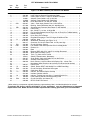
SECTION 11 − PARTS LIST EFF. W/MA080041J AND FOLLOWING
805 115-E
Diversion 165 Models
1
2
3
4
56
7
8
11
9
12
13
14
15
16
17
18
19
20
21
22
23
24
25
26
27
28
11
29
30
31
32
33
34
35
36
37
38
39
40
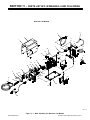
Figure 11-1. Main Assembly For Diversion 165 Models

EFF W/MA080041J AND FOLLOWING
TM-246 522 Page 75Diversion 165 And Diversion 180 w/Auto-Line
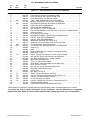
Description
Part
No.
Dia.
Mkgs.
Item
No.
Figure 11-1 . Main Assembly For Diversion 165 Models
Quantity
1 +232 868 Wrapper, 1... ............ .. ......................................................
2 230 366 Label, Warning General Precautionary Static 1... ............. .. ........................
3 232 915 Cord Set, 250v 6−50p 12ga 3/C 7ft Spt−3 Jkt 1... ............. .. .......................
4 188 048 Hose, Nprn Brd No 1 X .250 Id X 18.000 1... ............. .. ...........................
5 GS1 216 607 Valve, 24vdc 2way Custom Port 1/8 Orf W/Frict 1... .... ... .. .....................
6 111 443 Bushing, Strain Relief .240/.510 Id X .875 Mtg Hole 1... .............. .. ..................
7 CB1 233 184 Supplementary Protector, Man Reset 1p 35a 250vac 1... .... ... .. .................
8 232 865 Panel, Rear (Prior to MB080009J) 1... ............. .. .................................
8 246 515 Panel, Rear (Eff w/MB080009J) 1... ............. .. ...................................
9 137 761 Nut, 750 NPT 1.31 Hex .27 H Nyl Blk 1... ............. .. ..............................
10 232 940 Ftg, Hose Brs Barbed M 3/16 Tbg X 5/8−18 Thrd (Prior To MA270269J) 1... ............. ..
11 232 901 Handle, Carrying 2... ............. .. ................................................
12 248 169 Hose, Gas 12 Ft w/Fittings 1... ............. .. .......................................
13 234 263 Regulator/Flowgauge, 0−50 CFH Argon/CO2/Mix/w/Filter 1... ............. .. .............
14 L1 237 414 Inductor, Input (Prior to MB080009J) 1... ..... .... .. ...............................
14 L1 250 734 Inductor, Input (Eff w/MB080009J) 1... ..... .... .. .................................
15 232 922 Windtunnel, Assembly (see Figure 11-3) 1... ............. .. ............................
16 083 147 Grommet, Scr No 8/10 Panel Hole .312 Sq .500 High 4... ............. .. ................
17 PC1 240 718 Circuit Card Assy, Control & Interface 1... .... ... .. ..............................
18 FM1 232 923 Fan, Muffin 24vdc 4500 Rpm 240 Cfm 4.125 Mtg Holes 1... .... ... .. ..............
19 232 866 Plenum, Air 1... ............. .. .....................................................
20 232 863 Base 1... ............. .. ..........................................................
21 239 388 Bumper, RBR .875 OD X .188 ID X .39 High Recessed 4... ............. .. ..............
22 233 200 Cable Assy, RJ45 1... ............. .. ...............................................
23 S2 134 847 Switch, Tgl Spdt 15a 125vac On−none−on Spd Term Blk 1... ..... .... .. .............
24 231 238 Nut, 468−32 .56 Hex .09 H Brs Blk Use w/Switches 2... ............. .. ..................
25 217 839 Nut, Nylon Strain Rlf Pg13.5 .250thk 1.062od 1... ............. .. .......................
26 232 908 Work Cable, W/Clamp (12’) 1... ............. .. .......................................
27 235 392 Torch, Tig 150a 12ft Air Cooled 1... ............. .. ....................................
28 233 187 Strain Relief, Cable .250 Cable Dia .5x.450 D Hole 1... ............. .. ...................
29 207 079 Knob, Pointer 1.125 Dia 1... ............. .. ..........................................
30 178 355 Nut, 375−32 .54 Hex .25 H Nyl Flange .62 D 1... ............. .. ........................
31 232 896 Nameplate, Miller Diversion 165 1... ............. .. ...................................
32 232 864 Panel, Front 1... ............. .. ....................................................
33 232 320 Nut, Nylon Thd Pg 16 1... ............. .. ............................................
34 S1 124 511 Switch, Tgl Dpst 40a 600vac Scr Term 1... ..... ..... .. .............................
35 P1 233 165 Pot Assy, W/Leads & Connector & Leds Cp Flat 1t 2. 1... ..... .... .. ................
36 T2 232 909 Inductor, Arc Starter/Output 150 Amp 1... ..... .... .. ..............................
37 PC3 228 593 Circuit Card Assy, Arc Starter 1
... .... ... .. .....................................
38 L2 208 066 Inductor, Toroid 5 Amp 180 Uh, 12” Leads W/Quick Con 1... ..... .... .. ..............
39 210 323 Insulator, Washer Inductor 1... ............. .. ........................................
40 185 835 Label, Warning Electric Shock/Exploding Parts 1... ............. .. ......................
+When ordering a component originally displaying a precautionary label, the label should also be ordered.
To maintain the factory original performance of your equipment, use only Manufacturer’s Suggested
Replacement Parts. Model and serial number required when ordering parts from your local distributor.

EFF W/MA080041J AND FOLLOWING
TM-246 522 Page 76 Diversion 165 And Diversion 180 w/Auto-Line
805 479-B
Diversion 180 Models
1
2
3
4
5
6
7
8
11
9
12
13
14
15
16
17
18
19
20
21
22
23
24
11
25
26
27
28
29
30
31
32
33
34
35
36
37
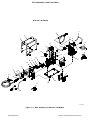
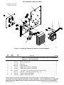
Figure 11-2. Main Assembly For Diversion 180 Models

EFF W/MA080041J AND FOLLOWING
TM-246 522 Page 77Diversion 165 And Diversion 180 w/Auto-Line
Description
Part
No.
Dia.
Mkgs.
Item
No.
Figure 11-2. Main Assembly For Diversion 180 Models
Quantity
1 +232 868 Wrapper, 1... ............ .. ......................................................
2 230 366 Label, Warning General Precautionary Static 1... ............. .. ........................
3 241 271 Cable, power 10 ft 2 in. 14GA 3C w/ MVP & Adapter 1... ............. .. .................
219261 Adapter, Power Cable 5-15P (115V/15A 1.................... .. ............................
219258 Adapter, Power Cable 6-50P (230V/50A 1.................... .. ............................
4 188 048 Hose, Nprn Brd No 1 X .250 Id X 18.000 1... ............. .. ...........................
5 GS1 216 607 Valve, 24vdc 2way Custom Port 1/8 Orf W/Frict 1... .... ... .. .....................
6 217 028 Bushing, Strain Relief.390/.560 Id X .830 Mtg Hole 1... ............. .. ...................
7 CB1 233 184 Supplementary Protector, Man Reset 1P 35A 250VAC 1... .... ... .. ...............
8 246 515 Panel, Rear 1... ............. .. .....................................................
9 137 761 Nut, 750 NPT 1.31 Hex .27 H Nyl Blk 1... ............. .. ..............................
10 232 940 Ftg, Hose Brs Barbed M 3/16 Tbg X 5/8−18 Thrd (Prior To MA270269J) 1... ............. ..
11 232 901 Handle, Carrying 2... ............. .. ................................................
12 248 169 Hose, Gas 12 ft w/Fittings 1... ............. .. ........................................
13 234 263 Regulator/Flowgauge, 0−50 CFH Argon/CO2/Mix w/Filler 1... ............. .. .............
14 L1 246 538 Inductor, Input 1... ..... .... .. ..................................................
15 +246 525 Windtunnel, Assembly (see Figure 11-3) 1... ............ .. ............................
16 083 147 Grommet, Scr No 8/10 Panel Hole .312 Sq .500 High 4... ............. .. ................
17 PC1 244 389 Circuit Card Assy, Control 1... .... ... .. ........................................
18 FM1 232 923 Fan, Muffin 24vdc 4500 Rpm 240 Cfm 4.125 Mtg Holes 1... .... ... .. ..............
19 232 866 Plenum, Air 1... ............. .. .....................................................
20 232 863 Base 1... ............. .. ..........................................................
21 239 388 Bumper, RBR .875 OD X .188 ID X .39 High Recessed 4... ............. .. ..............
22 232 908 Work Cable, W/Clamp (12 Ft) 1... ............. .. .....................................
23 235 392 Torch, Tig 150a 12ft Air Cooled 1... ............. .. ....................................
LS0011 Switch & Potentiometer, Momentary 1.................... .. ...............................
24 233 187 Strain Relief, Cable .250 Cable Dia .5x.450 D Hole 1... ............. .. ...................
25 231 297 Actuator Push Button Assy 1... ............. .. .......................................
26 228 546 Knob, Pointer 1.125 Dia x 6mm Id W/Spring Clip− 4.5mm Flat 1... ............. .. ........
27 Nameplate, Miller Diversion 180 (order by model and serial number) 1... ........................ ...
28 246 541 Panel, Front 1... ............. .. ....................................................
29 S1 208 550 Switch, Rocker DPST 16A 250VAC On−off Blk Panel Mtg 1... ..... .... .. .............
30 PC4 244 354 Circuit Card Assy, & Interface W/Program 1... .... ... .. ..........................
31 233 200 Cable Assy, RJ45 1... ............. .. ...............................................
32 T2 246 530 Inductor, Arc Starter/Output 150 Amp 1... ..... .... .. ..............................
33 210 323 Insulator, Washer Inductor 1... ............. .. ........................................
34 L2 208 066 Inductor, Toroid 5 Amp 180 Uh, 12” Leads W/Quick Con 1... ..... .... .. ..............
35 185 835 Label, Warning Electric Shock/Exploding Parts 1... ............. .. ......................
36 PC3 235 476 Circuit Card Assy, Arc Starter (R) 1... .... ... .. ..................................
37 245 589 RFCS−RJ45 Foot Control 1... ............. .. ........................................
+When ordering a component originally displaying a precautionary label, the label should also be ordered.
To maintain the factory original performance of your equipment, use only Manufacturer’s Suggested
Replacement Parts. Model and serial number required when ordering parts from your local distributor.

EFF W/MA080041J AND FOLLOWING
TM-246 522 Page 78 Diversion 165 And Diversion 180 w/Auto-Line
805 135-C
. Hardware is common and
not available unless listed.
1
2
3
4
5
6
7
8
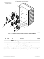
Figure 11-3. Windtunnel Assembly For Diversion 165 And 180 Models
Description
Part
No.
Dia.
Mkgs.
Item
No.
Figure 11-3. Windtunnel Assembly For Diversion 165 And 180 Models
(Figures 11-1 And 11-2, Item 15)
Quantity
1 PC2 230 144 Circuit Card Assy, Commutator Control 1... ... . .. ................................
2 242 084 Bushing, Snap-In Nyl 6... .......... .. ................................................
3 212 458 Stand-Off 4... .......... .. ..........................................................
4 +232 867 Panel, Midplane 1... ........ .. ....................................................
5 T1 237 413 XFMR, Main (Includes) (165 Models) 1... .... .. .. ..................................
5 T1 246 540 XFMR, Main (Includes) (180 Models) 1... .... .. .. ..................................
6 RT3 207 890 Thermistor, NTC 10K Ohm @ 25 Deg C 27.50 In Lead 1... ... . .... ................
7 232 917 Heat Sink, Secondary Assy (See Figure 11-4) 1... ......... .. ..........................
8 Z1 237 412 Inductor, Output (165 Models) 1... .... .. .. ........................................
8 Z1 246 539 Inductor, Output (180 Models) 1... .... .. .. ........................................
+When ordering a component originally displaying a precautionary label, the label should also be ordered.
To maintain the factory original performance of your equipment, use only Manufacturer’s Suggested
Replacement Parts. Model and serial number required when ordering parts from your local distributor.

EFF W/MA080041J AND FOLLOWING
TM-246 522 Page 79Diversion 165 And Diversion 180 w/Auto-Line
805 123-A
. Hardware is common and
not available unless listed.
1
2
6
3
3
3
3
5
4
Figure 11-4. Heat Sink, Secondary Assembly For Diversion 165 And 180 Models
Description
Part
No.
Dia.
Mkgs.
232 917
Item
No.
Figure 11-4. Heat Sink, Secondary Assembly For Diversion 165 And 180
Models (Figure 11-3, Item 7)
Quantity
1 232 869 Heat Sink, Secondary 1... ......... .. ...............................................
2 D9,D12 231 396 Diode, Ultra-Fast Recovery 90 A 600 V Dual SOT-227 2... .. .. ..................
3 Q2,3,4,5 231 393 Transistor, IGBT 100 A 600 V SOT-227 4... . .. ...............................
4 RT2 213 353 Thermistor, NTC 30K Ohm @ 25 Deg C 8 In Lead 1... ... . .. ......................
5 212 038 Screw, M4 .7 x 8.5 Pan HD-PHL STL PLD Sems Split/Fl 15... ......... .. ................
6 SR1 199 952 Diode, Power Module 50 Amp 600 V 1 PH Fast Recovery 1... ... . .. ...............
To maintain the factory original performance of your equipment, use only Manufacturer’s Suggested
Replacement Parts. Model and serial number required when ordering parts from your local distributor.

ORIGINAL INSTRUCTIONS − PRINTED IN USA 2011 Miller Electric Mfg. Co.
Miller Electric Mfg. Co.
An Illinois Tool Works Company
1635 West Spencer Street
Appleton, WI 54914 USA
International Headquarters−USA
USA Phone: 920-735-4505 Auto-Attended
USA & Canada FAX: 920-735-4134
International FAX: 920-735-4125
For International Locations Visit
www.MillerWelds.com
-
 1
1
-
 2
2
-
 3
3
-
 4
4
-
 5
5
-
 6
6
-
 7
7
-
 8
8


Miller MB260624J Instrukcja obsługi
- Kategoria
- System spawalniczy
- Typ
- Instrukcja obsługi
- Niniejsza instrukcja jest również odpowiednia dla
Powiązane artykuły
-
Miller MB510007L Instrukcja obsługi
-
-
Miller LK300111J Instrukcja obsługi
-
Miller ProHeat 35 Instrukcja obsługi
-
-
-
-
-
-