Eneo Minitrax HDD-1012PTZ1080 Quick Installation Manual
- Kategoria
- Komponenty urządzeń zabezpieczających
- Typ
- Quick Installation Manual

Quick Installation Guide
1/2.8" HDcctv Dome, Day&Night
HDD-1012PTZ1080
DE
EN
FR
PL
RU

22
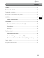
Inhalt
Inhalt ...........................................................................................................................2
Sicherheitshinweise .................................................................................................3
Lieferumfang .............................................................................................................3
Produktbeschreibung und Anschlüsse ................................................................4
Installation ................................................................................................................5
Domekamera verriegeln .......................................................................................6
Konfiguration .............................................................................................................7
Einstellung der Adresse (ID) der Domekamera .....................................................7
Anschlüsse ............................................................................................................8
Erste Schritte ........................................................................................................8
Bedienung .................................................................................................................9
Domekameraauswahl ...........................................................................................9
Zugriff auf das OSD-Menü .................................................................................... 9
Bedienung des OSD-Menüs ...............................................................................10
Fastrax Protocol ................................................................................................... 11
Weitere Informationen ......................................................................................... 12

3
DE
EN
FR
PL
RU
3
DE
EN
FR
PL
RU
Sicherheitshinweise
Bitte beachten Sie auch die beiliegenden Sicherheitshinweise und lesen Sie
diese Anleitung vor Inbetriebnahme sorgfältig durch.
Wichtige Hinweise sind mit einem Achtung-Symbol gekennzeich-
net.
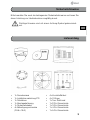
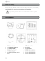
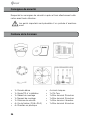
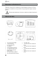
Lieferumfang
• 1x Domekamera
• 1x Installationsanleitung/CD
• 1x Schablone
• 1x Montagehalterung
• 1x Sicherheitskabel
• 4x Befestigungsschraube
(PH6 x 35.0)
• 4x Kunststoffdübel
• 4x O-Ringe
• 1x Torx Schlüssel
• 1x 2-Pin Klemmleiste
• 1x 3-Pin Klemmleiste
• 1x 4-Pin Klemmleiste
• 1x 5-Pin Klemmleiste

44
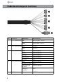
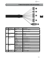
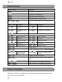
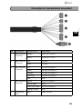
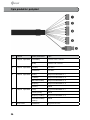
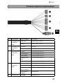
Nr. Anschluss Kabelfarbe Beschreibung
1 3-Pin Klemmleiste Rot 24VAC oder 12VDC+
Weiß 24VAC oder 12VDC-
2 2-Pin Klemmleiste Grün RS-485+
Blau RS-485-
3 5-Pin Klemmleiste Grau Alarmeingang 1
Violett Alarmeingang 2
Orange Alarmeingang 3
Himmelblau Alarmeingang 4
Schwarz GND
4 4-Pin Klemmleiste Gelb Alarmausgang 1
Schwarz & Weiß GND
Himmelblau &
Schwarz
Alarmausgang 2
Orange &
Schwarz
GND
5 BNC-Anschluss Blau HD-SDI Ausgang
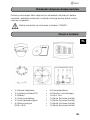
Produktbeschreibung und Anschlüsse

5
DE
EN
FR
PL
RU
5
DE
EN
FR
PL
RU
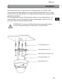
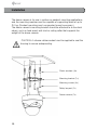
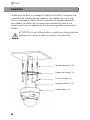
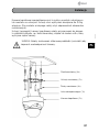
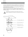
Installation
Die Domekamera ist für den Einsatz in Anwendungen mit Aufbau- oder
Abhängungsmontagen geeignet und das Befestigungselement muss Trage-
lasten bis 2,0 kg unterstützen. (Für Abhängungsmontage wird Hängemonta-
gezubehör benötigt.)
Die Montagehalterung der Domekamera sollte an einem Bauelement, wie
etwa Hartholz, einem Wandständer oder Deckenbalken, welches das Ge-
wicht der Kamera trägt, befestigt werden.
WARNUNG: Es muss ein Silikon-Dichtmittel verwendet werden,
um die Wasserdichtigkeit des Gehäuses sicherzustellen.
Kunststoffdübel (4x)
Montagehalterung (1x)
Befestigungsschrauben (4x)
Sicherheitskabel (1x)
Domekamera (1x)

66
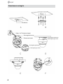
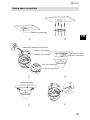
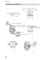
Domekamera verriegeln
Schablone
Haken für Sicherheitskabel
Montagehalterung
Verriegelungslasche
Verriegelungsschlitz
Verriegelungsschraube
Verriegelungslasche
Verriegelungsschlitz
Sicherheitskabel

7
DE
EN
FR
PL
RU
7
DE
EN
FR
PL
RU
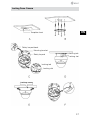
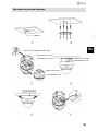
A. Bohren Sie die Löcher mit Hilfe der beiliegenden Schablone in die De-
cke (Abbildung A).
B. Befestigen Sie die Montagehalterung mit den beiliegenden Dübeln (4x)
und Befestigungsschrauben (4x) an der Decke (Abbildung B).
C. Hängen Sie das Sicherheitskabel an den Haken an der Montagehalte-
rung (Abbildung C).
D. Führen Sie die Verriegelungslasche an der Montagehalterung in den
Verriegelungsschlitz im Unterteil des Domes ein (Abbildung D).
E. Drehen Sie den Dome etwa 10° gegen den Uhrzeigersinn bis in die
Verriegelungsposition (Abbildung E).
WARNUNG: Bevor Sie die Montagehalterung an der Oberfläche
befestigen sollten Sie die Befestigungsschrauben "A" am Unterteil
der Domekamera vorjustieren damit Sie in der Verriegelungspositi-
on optimal passen. Drehen Sie die Verriegelungsschraube an der Seite des
Unterteil des Domes heraus und führen Sie die Lasche der Montagehalte-
rung in den Verriegelungsschlitz. Die Schrauben "A" sollten nicht zu fest
oder zu locker sitzen, wenn sich der Dome in der Verriegelungsposition
befindet. Nach dem Einstellen der passenden Position der Schrauben "A"
entfernen Sie die Montagehalterung und installieren sie an der gewünsch-
ten Fläche. Falls es zu schwierig ist, den Dome nach der Installation der
Montagehalterung in die Verriegelungsposition zu bringen, adjustieren Sie
die Schrauben "A", indem Sie sie etwas heraus drehen und versuchen Sie
die Installation erneut.
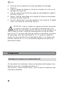
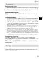
Konfiguration
Einstellung der Adresse (ID) der Domekamera
Zur Verhinderung von Beschädigungen muss an jeder Dome-Kamera eine
eigene Adresse (ID) eingestellt werden. Die Werkseinstellung ist 1.
Weitere Informationen entnehmen Sie bitte Abschnitt "Dome Communica-
tion" im Benutzerhandbuch.

88
Anschlüsse
Anschluss an RS485
Die Domekamera kann mit einem externen Gerät oder einem Steuersystem
wie etwa der Bedientastatur (Keyboard-Controller) über RS-485 Halbduplex-
Signale ferngesteuert werden.
HD-SDI Anschluss verbinden
Verbinden Sie den HD-SDI Anschluss (BNC) mit dem Monitor oder dem
Video-Eingang.
Anschließen von Alarmen
• A1,A2,A3,A4 (Alarmeingang 1,2,3,4) : Sie können externe Geräte an-
schließen, die der Dome-Kamera externe Ereignisse signalisieren, damit
sie auf diese reagiert. Mechanische oder elektrische Schalter können
zwischen die Anschlüsse A1,A2,A3,A4 (Alarmeingang 1,2,3,4) und G
(Masse) geschaltet werden. Zur Konfiguration der Alarmeingänge siehe
„Program and Operation“ im Benutzerhandbuch.
• HINWEIS: Alle mit G oder GND gekennzeichneten Anschlüsse verfügen
über eine gemeinsame Masse. Schließen Sie die Masseseite des Alar-
mein- und/oder -ausgangs an den Anschluss G (Masse) an.
• AO1,AO2 (5VTTL Alarmausgang 1,2): Die Dome-Kamera kann externe
Geräte wie Signalhörner oder Alarmleuchten aktivieren. Schließen Sie
das Gerät an die Anschlüsse AO1,AO2 (Alarmausgang 1,2) und G
(Erdung) an. Zur Konfiguration des Alarmausgangs siehe „Program and
Operation“ in the Full Manual.
Anschluss der Stromversorgung
Schließen Sie die Stromversorgung von 24VAC oder 12VDC 1,5A an die
Dome-Kamera an.
Bei Verwendung eines 12VDC-Netzteils die Plus-Leitung (+) an „+“ und die
Minus-Leitung (–) an „-“ anschließen.
Verwenden Sie nur zertifizierte/gelistete Netzteile der Klasse2.
Erste Schritte
Nach der Installation schalten Sie die Stromversorgung zur Kamera ein. Die
Domekamera wird eine Konfigurationssequenz beginnen.

9
DE
EN
FR
PL
RU
9
DE
EN
FR
PL
RU
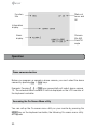
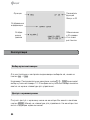
Bedienung
Funktions-
bezeichnung
Anzeige
Kameradaten
Alarmanzeige
Status von
Focus und
AE
Kameratitel &
ID Schwenk-/
Neigewinkel
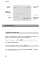
Domekameraauswahl
Bevor Sie die Domekamera programmieren oder bedienen, müssen Sie sie
drücken der No. + CAM Tasten auswählen.
Beispiel: Aufeinander folgendes Drücken der Tasten1 , 0 + CAM wählt Do-
mekamera 10 aus. Die gewählte Kamera-ID wird auf dem LCD Bildschirm
der Bedientastatur angezeigt.
Zugriff auf das OSD-Menü
Sie können das OSD-Menü auf Ihrem Bildschirm durch drücken der MENU
Taste auf der Bedientastatur aktivieren, um den folgenden OSD Bildschirm
aufzurufen:

1010
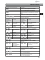
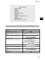
Bedienung des OSD-Menüs
Funktion Schaltfläche
Aufrufen des OSD-Menüs.
MENU
Navigation durch die Menüelemente.
Joystick nach oben/unten
Aufrufen der Untermenüs.
Joystick nach links/rechts oder
Blende öffnen
Wert ändern.
Modus zum Ändern des Titels
aktivieren.
Joystick nach links/rechts oder
Zoom Hebel drehen oder Tele , Wide
Wert des Winkels ändern.
CTRL + Joystick
Modus zum Ändern des Winkels
aufrufen.
IRIS Open
Modus zum Ändern des Winkels
verlassen.
IRIS Close
Verlassen (EXIT)
ESC

11
DE
EN
FR
PL
RU
11
DE
EN
FR
PL
RU
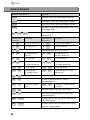
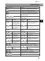
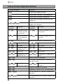
Fastrax Protocol
Kurzwahl-Tastenkombination Funktion
PRST
Preset Einstellungsmenü einblenden
TOUR
Tour Einstellungsmenü einblenden
PTRN
Bereichsabfahrt Einstellungsmenü einblen-
den
SCAN
Auto Scan Einstellungsmenü einblenden
No.+ CTRL+ PRST
Aktuelle Ansicht unter der ausgewählten
Nummer speichern
Kurzwahl-
Tastenkombi-
nation
Funktion Kurzwahl-
Tastenkombi-
nation
Funktion
7 + ON
FOCUS auf AUTO
umschalten
7 + OFF
FOCUS auf MANUAL
umschalten
8 + ON
AE auf AUTO um-
schalten
8 + OFF
AE auf MANUAL
umschalten
9 + ON
Nachtaufnahme auf AUTO umschalten
10 + ON
Nachtaufnahme
ein
10 + OFF
Nachtaufnahme aus
11 + ON
BLC ein
11 + OFF
BLC aus
13 + ON
Dome OSD ein
13 + OFF
Dome OSD aus
104 + ON
WDR ein
104 + OFF
WDR aus
150 + ON
Bildumkehr ein
150 + OFF
Bildumkehr aus
151 + ON
Ausgangspunkt-Prüfung
152 + ON
Kamera horizontal in die 0°-Position
bringen.
153 + ON
Langsame
Geschwindigkeit
einschalten
153 + OFF
Normale Geschwindigkeit
einschalten
154 + ON
Systeminformationen anzeigen
155 + ON
Kamera in der 180°-Position horizontal
umkehren.
888 + ENTER
Nachtaufnahme-Modus ein
(nur im Global-Modus)
999 + ENTER
Nachtaufnahme-Modus aus
(nur im Global-Modus)

1212
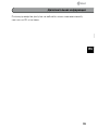
Weitere Informationen
Das Benutzerhandbuch ist auf der eneo Website unter
www.eneo-security.com oder auf der mitgelieferten CD verfügbar.

13
DE
EN
FR
PL
RU
Contents
Contents ................................................................................................................. 13
Notes on safety ..................................................................................................... 14
Parts supplied ........................................................................................................ 14
Product description and connections ............................................................... 15
Installation .............................................................................................................. 16
Locking Dome Camera .......................................................................................17
Setup ....................................................................................................................... 18
Setting Dome Camera Address (ID) ....................................................................18
Connections ......................................................................................................... 19
Getting started ....................................................................................................19
Operation ................................................................................................................ 20
Dome camera selection ......................................................................................20
Accessing the On-Screen Menu utility ................................................................ 20
How to control the On-Screen Menu utility .........................................................21
Fastrax Protocol ................................................................................................... 22
Further information .............................................................................................. 22

14
Notes on safety
Please also pay attention to the enclosed safety instructions, and carefully
read through this instruction guide before initial operation.
Important points of advice are marked with a caution symbol.
Parts supplied
• 1x Dome camera
• 1x Installation guide/CD
• 1x Template sheet
• 1x Mounting bracket
• 1x Safety lanyard
• 4x Mounting screws (PH6 x
35.0)
• 4x Plastic anchors
• 4x O-Rings
• 1x Torx wrench
• 1x 2-Pin Terminal block
• 1x 3-Pin Terminal block
• 1x 4-Pin Terminal block
• 1x 5-Pin Terminal block

15
DE
EN
FR
PL
RU
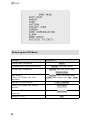
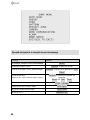
NO Connector Wire color Description
1 3-pin terminal
block
Red 24VAC or 12VDC+
White 24VAC or 12VDC-
2 2-pin terminal
block
Green RS-485+
Blue RS-485-
3 5-pin terminal
block
Gray ALARM INPUT 1
Violet ALARM INPUT 2
Orange ALARM INPUT 3
Sky Blue ALARM INPUT 4
Black GND
4 4-pin terminal
block
Yellow ALARM OUTPUT 1
Black & White GND
Sky Blue & Black ALARM OUTPUT 2
Orange & Black GND
5 BNC jack Blue HD-SDI Output
Product description and connections

16
Installation
The dome camera is for use in surface or pendent mounting applications,
and the mounting member must be capable of supporting loads of up to
2.0 kg. (Pendent mounting must use pendent mount accessory.)
The dome camera’s mounting bracket should be attached to a structural
object, such as hard wood, wall stud or ceiling rafter that supports the
weight of the dome camera.
CAUTION: A silicone rubber sealant must be applied to seal the
housing to secure waterproofing.
Plastic anchors (4x)
Mounting bracket (1x)
Mounting screws (4x)
Safety lanyard (1x)
Dome camera (1x)

17
DE
EN
FR
PL
RU
Locking Dome Camera
Template sheet
Safety lanyard hook
Mounting bracket
Locking tab
Locking slot
Locking screw
Locking tab
Locking slot
Safety lanyard

18
A. Make screw holes on the ceiling using the supplied mounting Template
Sheet (Figure A).
B. Fix the Mounting Bracket to the ceiling using supplied Anchors (4x) and
Mounting Screws (4x) (Figure B).
C. Hook up the Safety Lanyard to the Safety Lanyard Hook of the Mounting
Bracket (Figure C).
D. Align the locking tab on the bracket and the locking slot on the base of
the dome (Figure D).
E. Turn the dome to the counterclockwise about 10 degree to the locked
position (Figure E).
CAUTION: Before installing mounting bracket to surface pre-adjust
the four mounting screws „A“ on the base of the dome camera to
best match the mounting bracket locked position. Unscrew the
locking screw on the side of the dome‘s base and fit the tab of the moun-
ting bracket into the locking slot. Screws „A“ should not be too tight or too
loose when the dome is in the locked position. After setting the proper
positions of screws „A“ remove the mounting bracket and install it to the
proper surface. If it is too difficult to lock the dome in position after the
mounting bracket has been installed readjust the screws „A“ by unscrewing
them a small amount and try to install dome camera again.
Setup
Setting Dome Camera Address (ID)
To prevent damage, each Dome Camera must have a unique address (ID).
The factory default setting is 1.
Refer to „Dome Communication“ section in the Full Manual for detailed
information.

19
DE
EN
FR
PL
RU
Connections
Connecting to the RS485
The Dome Camera can be controlled remotely by an external device or
control system, such as a control keyboard, using RS485 half-duplex serial
communications signals.
Connecting HD-SDI Output connector
Connect the HD-SDI output (BNC) connector to the monitor or video input.
Connecting Alarms
• A1,A2,A3,A4 (Alarm Input 1,2,3,4) : You can use external devices to
signal the dome camera to react on events. Mechanical or electrical
switches can be wired to the A1,A2,A3,A4 (Alarm Input 1,2,3,4) and G
(Ground) connectors. See „Program and Operation“ in the Full Manual
for configuring alarm input.
• G (Ground): NOTE: All the connectors marked G or GND are common.
Connect the ground side of the alarm input and/or alarm output to the
G (Ground) connector.
• AO1,AO2 (5VTTL Alarm Output 1,2): The dome camera can activate
external devices such as buzzers or lights. Connect the device to the
AO1,AO2 (Alarm Output 1,2) and G (Ground) connectors. See „Pro-
gram and Operation“ in the Full Manual for configuring alarm output.
Connecting the Power
Connect power of 24VAC or 12VDC 1.5A for the dome camera.
When using a 12VDC adapter, connect the positive (+) pole to the ‘+’ positi-
on and the negative (-) pole to the ‘-’ position.
Use satisfy clause 2.5 of IEC60950-1/UL60950-1 or Certified/Listed Class
2 power source only.
Getting started
Once installed apply power to the dome camera. The dome camera will
start a configuration sequence.

20
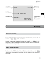
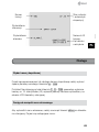
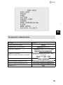
Operation
Function
title
Information
display
Alarm
display
Status of
focus and
AE
Camera
title &ID
Pan&Tilt
angle
Dome camera selection
Before you program or operate a dome camera, you must select the dome
camera by pressing No. + CAM keys.
Example: Pressing 1 , 0 + CAM keys sequentially will select dome camera
10. The selected dome camera ID will be displayed on the LCD monitor of
the keyboard controller.
Accessing the On-Screen Menu utility
You can call up the On-screen menu utility on your monitor by pressing the
MENU key on the keyboard controller, the following On-screen menu utility
will appear:
Strona się ładuje...
Strona się ładuje...
Strona się ładuje...
Strona się ładuje...
Strona się ładuje...
Strona się ładuje...
Strona się ładuje...
Strona się ładuje...
Strona się ładuje...
Strona się ładuje...
Strona się ładuje...
Strona się ładuje...
Strona się ładuje...
Strona się ładuje...
Strona się ładuje...
Strona się ładuje...
Strona się ładuje...
Strona się ładuje...
Strona się ładuje...
Strona się ładuje...
Strona się ładuje...
Strona się ładuje...
Strona się ładuje...
Strona się ładuje...
Strona się ładuje...
Strona się ładuje...
Strona się ładuje...
Strona się ładuje...
Strona się ładuje...
Strona się ładuje...
Strona się ładuje...
Strona się ładuje...
Strona się ładuje...
Strona się ładuje...
Strona się ładuje...
Strona się ładuje...
-
 1
1
-
 2
2
-
 3
3
-
 4
4
-
 5
5
-
 6
6
-
 7
7
-
 8
8
-
 9
9
-
 10
10
-
 11
11
-
 12
12
-
 13
13
-
 14
14
-
 15
15
-
 16
16
-
 17
17
-
 18
18
-
 19
19
-
 20
20
-
 21
21
-
 22
22
-
 23
23
-
 24
24
-
 25
25
-
 26
26
-
 27
27
-
 28
28
-
 29
29
-
 30
30
-
 31
31
-
 32
32
-
 33
33
-
 34
34
-
 35
35
-
 36
36
-
 37
37
-
 38
38
-
 39
39
-
 40
40
-
 41
41
-
 42
42
-
 43
43
-
 44
44
-
 45
45
-
 46
46
-
 47
47
-
 48
48
-
 49
49
-
 50
50
-
 51
51
-
 52
52
-
 53
53
-
 54
54
-
 55
55
-
 56
56


Eneo Minitrax HDD-1012PTZ1080 Quick Installation Manual
- Kategoria
- Komponenty urządzeń zabezpieczających
- Typ
- Quick Installation Manual
w innych językach
- français: Eneo Minitrax HDD-1012PTZ1080
Powiązane artykuły
-
Eneo HDB-1080Z03IR B Quick Installation Manual
-
-
-
-
-
-
-
Inne dokumenty
-
Abus TVHD50000 Instrukcja obsługi
-
Abus TVHD40000 Instrukcja obsługi
-
-
Abus TVHD60010 Instrukcja obsługi
-
Abus TVHD51000 Instrukcja obsługi
-
Abus TVIP72500 Instrukcja obsługi
-
Abus TVAC31210 instrukcja
-
Abus TVCC34010 Instrukcja obsługi
-
Abus TVCC91700 Instrukcja obsługi
-
Abus TVCC40010 Instrukcja obsługi