
CENTRALE DI COMANDO
CONTROL UNIT
STEUEREINHEIT
CENTRALE DE COMMANDE
CENTRAL DE MANDO
CENTRALKA STEROWANIA
L8542124
Rev. 05/06/00
Libro istruzioni
Operating instructions
Betriebsanleitung
Livret d’instructions
Manual de instrucciones
Książeczka z instrukcjami
UNIONE NAZIONALE COSTRUTTORI
AUTOMATISMI PER CANCELLI, PORTE,
SERRANDE ED AFFINI
MATRIX
CP.BULL
MATRIX CP.BULL

3
Dichiarazione CE di conformità Déclaration CE de conformité
EC declaration of conrmity Declaracion CE de conformidad
EG-Konformitatserklarung Deklaracja UE o zgodności
Con la presente dichiariamo che il nostro prodotto
We hereby declare that our product
Hiermit erklaren wir, dass unser Produkt
Nous déclarons par la présente que notre produit
Por la presente declaramos que nuestro producto
Niniejszym oświadczamy że nasz produkt
MATRIX / CP.BULL
è conforme alle seguenti disposizioni pertinenti:
complies with the following relevant provisions:
folgenden einschlagigen Bestimmungen entspricht:
correspond aux dispositions pertinentes suivantes:
satisface las disposiciones pertinentes siguientes:
zgodny jest z poniżej wyszczególnionymi rozporządzeniami:
Direttiva sulla compatibilità elettromagnetica
(89/336/CCE, 93/68/CEE)
EMC guidelines (89/336/EEC, 93/68/EEC)
EMV-Richtlinie (89/336/EWG, 93/68/EWG)
Directive EMV (89/336/CCE, 93/68/CEE)
(Compatibilité électromagnétique)
Reglamento de compatibilidad electromagnética
(89/336/MCE, 93/68/MCE)
Wytyczna odnośnie zdolności współdziałania elektromagne-
tycznego (89/336/EWG, 93/68/EWG)
Benincà Luigi, Responsabile legale.
Sandrigo, 05/10/2005.
Direttiva sulla bassa tensione (73/23/CEE, 93/68/CEE)
Low voltage guidelines (73/23/EEC, 93/68/EEC)
Tiefe Spannung Richtlinie (73/23/EWG, 93/68/EWG)
Directive bas voltage (73/23/CEE, 93/68/CEE)
Reglamento de bajo Voltaje (73/23/MCE, 93/68/MCE)
Wytyczna odnośnie niskiego napięcia (73/23/EWG,
93/68/EWG)
Automatismi Benincà SpA
Via Capitello, 45
36066 Sandrigo (VI)
ITALIA

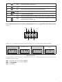
3
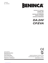
SERL:On
SERL:Off

4
5
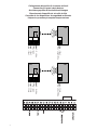
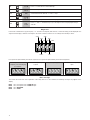
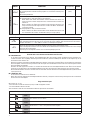
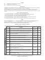
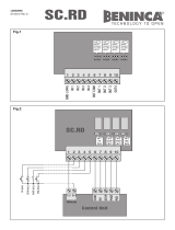
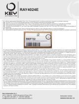
Collegamento dispositivi di sicurezza vericati
Connection of tested safety devices
Anschluss geprüfter Sicherheitsvorrichtungen
Branchement dispositifs de sécurité vériés
Conexión de los dispositivos de seguridad vericados
Połączenia sprawdzanych urządzeń bezpieczeństwa

4
5
Centrale di comando MATRIX/CP.BULL
La centrale elettronica MATRIX/CP.BULL può essere utilizzata per il controllo di 1 motore 230Vac con potenza non superiore a
1000W. Dispone di funzione di verica “Test singolo guasto” ai sensi della Direttiva Macchine 98/37/CE.
AVVERTENZE GENERALI
a) L’installazione elettrica e la logica di funzionamento devono essere in accordo con le normative vigenti.
b) I conduttori alimentati con tensioni diverse, devono essere sicamente separati, oppure devono essere adeguatamente isolati
con isolamento supplementare di almeno 1 mm.
c) I conduttori devono essere vincolati da un ssaggio supplementare in prossimità dei morsetti.
d) Ricontrollare tutti i collegamenti fatti prima di dare tensione.
e) Gli ingressi N.C. non utilizzati devono essere ponticellati.
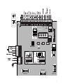
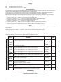
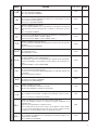
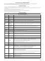
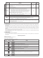
FUNZIONI INGRESSI/USCITE
Centrale MATRIX/CP.BULL
N° Morsetti Funzione Descrizione
1-2 Alimentazione Ingresso 230Vac 50Hz (1-Fase/2-Neutro)
3 GND Collegamento messa a terra (obbligatorio)
4-5 Antenna Collegamento antenna scheda radioricevente ad innesto (4-segnale/5-schermo).
6-7 RX 2° Ch Uscita secondo canale radio. Contatto N.O. libero da tensione.
8-9 24Vac Uscita alimentazione accessori 24Vac/500mA max
10-11
SCA o
Luce di servizio
Contatto pulito N.O. Congurabile come SCA (spia cancello aperto) o Luce di servizio tem-
porizzata (vedi Logica SERL).
12-13 PHOTO TEST
Contatto pulito N.O. Utilizzato per alimentare i trasmettitori delle fotocellule in modalità
TEST.
Vedi schema “Collegamento dispositivi di sicurezza vericati” e Logiche TST1 e TST2.
14 COM Comune per gli ingressi di comando.
15 OPEN Ingresso pulsante APRE (contatto N.O.).
16 CLOSE Ingresso pulsante CHIUDE (contatto N.O.)
17 Passo-Passo Ingresso pulsante passo-passo (contatto N.O.)
18 PED
Ingresso pulsante pedonale (contatto N.O.), comanda l’apertura parziale, congurabile dal
parametro TPED. Al termine del tempo TCA (se attivato) viene comandata la chiusura.
19 COM Comune per necorsa e sicurezze
20 STOP Ingresso pulsante STOP (contatto N.C.)
21 PHOT O
Ingresso (contatto N.C.) per dispositivi di sicurezza (ad es. fotocellule).
In fase di chiusura: l’apertura del contatto provoca l’arresto del motore quando la fotocellula
viene liberata, il motore inverte la direzione di marcia (apre).
In fase di apertura: l’apertura del contatto provoca l’arresto del motore, quando la fotocel-
lula viene liberata, il motore riparte in apertura.
22 SWO Ingresso necorsa APRE (contatto N.C.)
23 SWC Ingresso necorsa CHIUDE (contatto N.C.)
24 PHOT C
Ingresso (contatto N.C.) per dispositivi di sicurezza (ad es . fotocellule).
In fase di chiusura: Comportamento congurabile dalla logica PHTC.
In fase di apertura: Comportamento congurabile dalla logica PHTC.
25-26 DAS
Ingresso contatto costa sensibile
Costa resistiva: Jumper “DAS” chiuso
Costa meccanica: Jumper “DAS” aperto
L’intervento della costa arresta il movimento dell’anta e inverte per circa 3s se la logica.
Se non si utilizza la costa: Jumper “DAS” aperto, ponticello tra i morsetti 25-26.
27-28-29 Motore
Collegamento motore 230Vac - monofase:
27-Fase/28-Comune/29-Fase
27-30 Condensatore Collegamento condensatore
31-32 Lampeggiante Collegamento lampeggiante 230Vac 40W max.

6
7
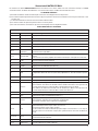
Fusibili
F1 Fusibile di protezione uscita motore e lampeggiante
F2 Fusibile di protezione trasformatore
F3 Fusibile protezione uscita accessori e segnali
Programmazione
La programmazione delle varie funzionalità della centrale viene effettuata utilizzando il display LCD presente a bordo della centrale
ed impostando i valori desiderati nei menu di programmazione descritti di seguito.
Il menu parametri consente di impostare un valore numerico ad una funzione, in modo analogo ad un trimmer di regolazione.
Il menu logiche consente di attivare o disattivare una funzione, in modo analogo al settaggio di un dip-switch.
Altre funzioni speciali seguono i menu parametri e logiche e possono variare a seconda del tipo di centrale o revisione software.
Per accedere alla programmazione:
1 Premere il pulsante <PG>, il display si porta nel primo menu Parametri “PAR”.
2 Scegliere con il pulsante <+> o <-> il menu che si intende selezionare (PAR>>LOG>>NMAN>>RES).
3 Premere il pulsante <PG>, il display mostra la prima funzione disponibile nel menu.
4 Scegliere con il pulsante <+> o <-> la funzione che si intende modicare.
5 Premere il pulsante <PG>, il display mostra il valore attualmente impostato per la funzione selezionata.
6 Selezionare con il pulsante <+> o <-> il valore che si intende assegnare alla funzione.
7 Premere il pulsante <PG>, il display mostra il segnale “PRG” che indica l’avvenuta programmazione.
Note:
La pressione simultanea di <+> e <-> effettuata all’interno di un menu funzione consente di tornare al menu superiore senza appor-
tare modiche.
La pressione simultanea di <+> e <-> effettuata a display spento visualizza la versione software della scheda.
Mantenere la pressione sul tasto <+> o sul tasto <-> per accelerare l’incremento/decremento dei valori.
Dopo un’attesa di 30s la centrale esce dalla modalità programmazione e spegne il display.
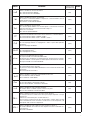
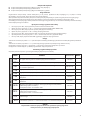
Parametri, Logiche e Funzioni Speciali
Nelle tabelle di seguito vengono descritte le singole funzioni disponibili nella centrale.
MENU FUNZIONE
Valori impostabili
MIN-MAX-(Default)
MEMO
PARAMETRI
TCA
Tempo di chiusura automatica. Attivo solo con logica “TCA”=ON.
Al termine del tempo impostato la centrale comanda una manovra di chiusura.
1-240-(40s)
Tped
Regola lo spazio percorso dall’anta durante l’apertura parziale (pedonale). 20-250-(50 cm)
Tsm
Regola lo spazio percorso dall’anta durante la fase di rallentamento.
0 = rallentamento disabilitato
0-250-(30 cm)
PMo
Regola la coppia applicata al motore durante la fase di apertura.* 1-99-(50%)
PMC
Regola la coppia applicata al motore durante la fase di chiusura.* 1-99-(50%)
Pso
Regola la coppia applicata al motore durante la fase di rallentamento in chiu-
sura*
1-99-(50%)
Psc
Regola la coppia applicata al motore durante la fase di rallentamento in aper-
tura*
1-99-(50%)
SeaU
Regola la soglia di intervento del dispositivo antischiacciamento (Encoder)
durante la fase a velocità normale*.
1:massima sensibilità - 99: minima sensibilità
1-99-(10%)
SEAR
Regola la soglia di intervento del dispositivo antischiacciamento (Encoder)
durante la fase di rallentamento*.
1:massima sensibilità - 99: minima sensibilità
1-99-(10%)
TLS
Attivo solo con logica SERL:ON. Regola il tempo di attivazione della luce di
servizio.
1-240-(60s)
Ibra
Regola la forza del freno motore.
0: frenatura disabilitata - 1:frenatura minima - 99: frenatura massima
0-99-(50%)
*ATTENZIONE:
Un’errata impostazione di questi parametri può risultare pericolosa.
Rispettare le normative vigenti!

6
7
MENU FUNZIONE
Valori impostabili
ON-OFF-(Default)
MEMO
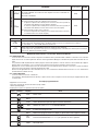
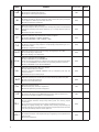
LOGICHE
TCA
Abilita o disabilita la chiusura automatica
On: chiusura automatica abilitata
Off: chiusura automatica disabilitata
(ON)
IbL
Abilita o disabilita la funzione condominiale.
On: funzione condominiale abilitata. L’impulso P.P. o del trasmettitore non ha
effetto durante la fase di apertura.
Off: funzione condominiale disabilitata.
(OFF)
SCL
Abilita o disabilita la chiusura rapida
On: chiusura rapida abilitata. Con cancello aperto o in movimento l’intervento
della fotocellula provoca la chiusura automatica dopo 3 s.
Attiva solo con TCA:ON
Off: chiusura rapida disabilitata.
(OFF)
PP
Seleziona la modalità di funzionamento del ”Pulsante P.P.” e del trasmettitore.
On: Funzionamento: APRE > CHIUDE > APRE >
Off: Funzionamento: APRE > STOP > CHIUDE > STOP >
(OFF)
PRE
Abilita o disabilita il pre-lampeggio.
On: Pre-lampeggio abilitato. Il lampeggiante si attiva 3s prima della partenza
del motore.
Off: Pre-lampeggio disabilitato.
(OFF)
LTCA
Abilita o disabilita il lampeggiante durante il tempo TCA.
On: Lampeggiante attivo.
Off: Lampeggiante non attivo.
(OFF)
CLOC
Seleziona la modalità dell’ingresso APRE
On: Ingresso APRE con funzionalità OROLOGIO.
Da utilizzare per collegamento a temporizzatore per apertura/chiusura a tempo.
(Contatto CHIUSO- cancello aperto, Contatto aperto, funzionamento normale).
Off: Ingresso APRE con funzionalità APRE
(OFF)
htr
Abilita o disabilita la funzione Uomo presente.
On: Funzionamento Uomo Presente.
La pressione dei pulsanti APRE/CHIUDE deve essere mantenuta durante tutta
la manovra.
Off: Funzionamento automatico.
(OFF)
IBCA
Abilita o disabilita i comandi PP e PED durante la fase TCA.
On: Comandi PP e PED non abilitati.
Off: Comandi PP e PED abilitati.
(OFF)
ENC
Abilita o disabilita l’Encoder.
On: Encoder abilitato, rallentamento attivato.
Off: Encoder disabilitato, rallentamento disattivato
(ON)
trk
Abilita o disabilita la verica integrità del TRIAC.
On: Verica attiva: se il TRIAC è guasto il motore non parte.
Off: non viene effettuata la verica del TRIAC.
(ON)
serL
Abilita o disabilita la funzione luce di servizio sull’uscita 10-11.
On: Ad ogni manovra il contatto viene chiuso per il tempo impostato con il pa-
rametro TLS
Utilizzare un relè ausiliario per il comando della luce.
Off: L’uscita ha la funzione SCA, spia cancello aperto: contatto aperto ad anta
chiusa, intermittente in fase di chiusura, contatto chiuso in fase di apertura e ad
anta aperta. Vedi schema di collegamento.
(OFF)
TST1
Abilita o disabilita la verica delle fotocellule sull’ingresso PHOT O.
On: Verica abilitata. Se la verica ha esito negativo non viene comandata nes-
suna manovra
Off: Verica disabilitata.
(OFF)

8
9
MENU FUNZIONE
Valori impostabili
ON-OFF-(Default)
MEMO
LOGICHE
TST2
Abilita o disabilita la verica delle fotocellule sull’ingresso PHOT C.
On: Verica abilitata. Se la verica ha esito negativo non viene comandata nes-
suna manovra
Off: Verica disabilitata.
(OFF)
PHTC
Seleziona la modalità di funzionamento dell’ingresso PHOT C.
On: Ingresso PHOT C attivo sia in apertura sia in chiusura.
In apertura: l’apertura del contatto provoca l’arresto del motore, quando la
fotocellula viene liberata, il motore riparte in apertura.
In chiusura: l’apertura del contatto provoca l’arresto del motore, quando la
fotocellula viene liberata, il motore inverte il senso di marcia (apre).
Off: Ingresso PHOT C attivo solo in chiusura.
In chiusura: l’apertura del contatto provoca l’arresto del motore e l’inversio-
ne istantanea del senso di marcia (apre).
(OFF)
MENU FUNZIONE
NMAN
Visualizza il numero di cicli completi (apre+chiude) effettuate dall’automazione.
La prima pressione del pulsante <PG>, visualizza le prime 4 cifre, la seconda pressione le ultime 4.
Es. <PG> 0012 >>> <PG> 3456: effettuati 123.456 cicli.
RES
RESET della centrale. ATTENZIONE!: Riporta la centrale ai valori di default.
La prima pressione del pulsante <PG> provoca il lampeggio della scritta RES, una ulteriore pressione del pul-
sante <PG> effettua il reset della centrale.
Modalità di funzionamento con Encoder abilitato/disabilitato
Con LOGICA ENC=ON:
- il sensore antischiacciamento è attivato. Regolare la sensibilità tramite i parametri SEAV e SEAR in conformità con le normative
vigenti. Anche una accurata regolazione del freno motore (parametro IBRA) può contribuire al rispetto delle normative di sicu-
rezza.
- se il parametro TSM>0 (rallentamento attivato) la prima manovra di apertura e chiusura avviene a velocità ridotta per l’appren-
dimento della corsa dell’anta, in caso contrario anche la prima manovra viene eseguita a velocità normale.
Registrata la corsa la centrale gestirà in modo automatico le fasi di rallentamento in apertura e chiusura. Lo spazio di rallenta-
mento può essere aumentato o diminuito dal parametro TSM.
Questa fase di apprendimento viene effettuata anche in caso di interruzione dell’alimentazione di rete o in caso di attivazione
del rallentamento (TSM da 0 a >0)
Con LOGICA ENC=OFF:
- il sensore antischiacciamento è disattivato.
- se il parametro TSM>0 (rallentamento attivato), la prima manovra viene eseguita a velocità normale per l’apprendimento della
corsa dell’anta.
Esempio programmazione
Supponiamo sia necessario:
- impostare un tempo di chiusura automatica (TCA) di 100s
- attivare il prelampeggio
eseguire passo a passo le operazioni descritte di seguito:
Passo Premere Display Note
1
PAR
Primo menu
2
TCA
Prima funzione del primo menu
3
040
Valore attualmente impostato per la funzione selezionata
4
100
Settare con i tasti <+> e <-> il valore desiderato
5
PRG
Il valore viene programmato
TCA
Effettuata la programmazione, il display si riporta alla funzione appena settata
6
PAR
Premere simultaneamente <+> e <-> per spostarsi al menu superiore
7
Log
Secondo menu

8
9
8
TCA
Prima funzione del secondo menu
9
Pre
Premere più volte <-> no a selezionare la logica PRE
10
OFF
Valore attualmente impostato per la funzione selezionata
11
ON
Settare con i tasti <+> e <-> il valore desiderato
12
PRG
Il valore viene programmato
Pre
Effettuata la programmazione, il display si riporta alla funzione appena settata
13
PAR
Premere simultaneamente <+> e <-> per tornare al menu superiore e uscire dalla
programmazione o attendere 30s.
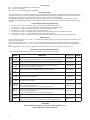
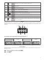
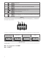
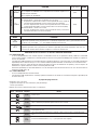
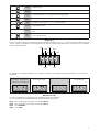
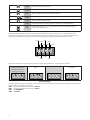
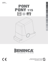
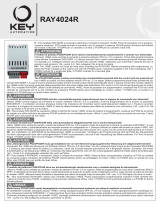
Diagnostica
Nel caso di anomalie di funzionamento è possibile visualizzare, premendo il tasto + o -, lo stato di tutti gli ingressi (necorsa, coman-
do e sicurezza). Ad ogni ingresso è associato un segmento del display che in caso di attivazione si accende, secondo il seguente
schema.
Gli ingressi N.C. sono rappresentati dai segmenti verticali. Gli ingressi N.O. sono rappresentati dai segmenti orizzontali.
Ad esempio, con le ante in
completa chiusura la visualiz-
zazione è la seguente:
nel momento in cui viene dato
un impulso Open:
durante la fase di apertura: con le ante in completa
apertura:
Messaggi di errore
La centrale verica il corretto funzionamento dei dispositivi di sicurezza. In caso di malfunzionamento possono essere visualizzati
dal display i seguenti messaggi:
ERR1 Errore verica fotocellule sull’ingresso PHOT O.
ERR2 Errore verica fotocellule sull’ingresso PHOT C.
ERR3 Errore ENCODER
ERR4 Errore TRIAC

10
11
MATRIX/CP.BULL Control Unit
The MATRIX/CP.BULL electronic control unit can be used to control 1 230Vac motor, with power not exceeding 1000W.
It is provided with “Single fault test” function, in compliance with the Machinery Directive 98/37/EC.
GENERAL WARNINGS
a) The electrical installation and the operating logic must comply with the regulations in force.
b) The leads fed with different voltages must be physically separate, or they must be suitably insulated with additional insulation of
at least 1 mm.
c) The leads must be secured with an additional xture near the terminals.
d) Check all the connections again before switching on the power.
e) The unused N.C. inputs must be bridged.
INPUT/OUTPUT FUNCTIONS
MATRIX/CP.BULL Control Unit
Terminal No. Function Description
1-2 Power supply Input, 230Vac 50Hz (1-Phase/2-Neutral)
3 GND Connection to ground (compulsory)
4-5 Aerial Connection of the insertable radio receiver card (4-signal/5-display).
6-7 RX 2° Ch Output, second radio channel of the receiver. N.O. voltage-free contact.
8-9 24Vac Output: power supply of accessories, 24Vac/500mA max.
10-11
SCA o
Service light
Normally Open (N.O.) free contact. Conguration like SCA (open gate warning LED) or timed
service light (see SERL Logic).
12-13 PHOTO TEST
N.O. free contact. It is used to power photocell transmitters in TEST operating mode.
See diagram “Connection of tested safety devices” and TST1 and TST2 Logic.
14 COM Common for control inputs.
15 OPEN Input, OPEN push-button (N.O. contact).
16 CLOSE Input, CLOSE push-button (N.O. contact)
17 Step-by-Step Input, step-by-step push-button (N.O. contact)
18 PED
Input, pedestrian push-button (N.O. contact). It controls the partial opening. Conguration is
through parameter TPED. When TCA time has elapsed (if activated) a closure control signal
is sent.
19 COM Common, for limit switches and safety devices
20 STOP Input, STOP push-button (N.C. contact)
21 PHOT O
Input, (N.C. contact) for safety devices (e.g. photocells).
In the closing phase: the contact opening causes the motor stop. Common: when the pho-
tocell is released, the motor inverts the movement direction (open).
In the opening phase: the contact opening causes the motor stop. When the photocell is
released, the motor re-starts the opening operation.
22 SWO Input, OPEN limit switch (N.C. contact)
23 SWC Input, CLOSE limit switch (N.C. contact)
24 PHOT C
Input (N.C. contact) for safety devices (e.g. photocells).
In the closing phase: Conguration through PHTC Logic.
In the opening phase: Conguration through PHTC Logic.
25-26 DAS
Input, safety edge
Resistive edge: “DAS” Jumper closed
Mechanical edge: “DAS” Jumper open
When the edge is activated, the gate movement is stopped and reversed for about 3s.
If the edge is not in use: “DAS” Jumper open, 25-26 terminals are short-circuited.
27-28-29 Motor
Connection of motor 230Vac - single-phase:
27-Phase/28-Common/29-Phase
27-30 Capacitor Connection of capacitor
31-32 Blinker Connection of blinker, 230Vac 40W max.

10
11
Fuses
F1 Output protection fuse for motor and blinker
F2 Protection fuse of transformer
F3 Output protection fuse of accessories and signals
Programming
The programming of the various functions of the control unit is carried out using the LCD display on the control unit and setting
the desired values in the programming menus described below.
The parameters menu allows you to assign a numerical value to a function, in the same way as a regulating trimmer.
The logic menu allows you to activate or deactivate a function, in the same way as setting a dip-switch.
Other special functions follow the parameters and logic menus and may vary depending on the type of control unit or the software
release.
To access programming:
1 Press the button <PG>, the display goes to the rst menu, Parameters “PAR”.
2 With the <+> or <-> button, select the menu you want (PAR>>LOG>>NMAN>>RES)
3 Press the button <PG>, the display shows the rst function available on the menu.
4 With the <+> or <-> button, select the function you want.
5 Press the button <PG>, the display shows the value currently set for the function selected.
6 With the <+> or <-> button, select the value you intend to assign to the function.
7 Press the button <PG>, the display shows the signal “PRG” which indicates that programming has been completed.
Notes:
Simultaneously pressing <+> and <-> from inside a function menu allows you to return to the previous menu without making any
changes.
Simultaneously pressing <+> and <-> when the display is switched off shows the card software release.
Hold down the <+> key or the <-> key to accelerate the increase/decrease of the values.
After waiting 30s the control unit quits programming mode and switches off the display.
Parameters, Logic and Special Functions
The tables below describe the individual functions available in the control unit.
MENU FUNCTION
Settable values
MIN-MAX-(Default)
MEMO
PARAMETERS
TCA
Automatic closure time. It is activated only with “TCA”=ON logic.
At the end of the preset time, the control unit controls a closure operation.
1-240-(40s)
Tped
The area covered by the gate during its partial opening movement (pedestrian)
is adjusted.
20-250-(50 cm)
Tsm
The area covered by the gate during the braking phase is adjusted.
0 = braking disabled
0-250-(30 cm)
PMo
The torque applied to the motor in the opening phase is adjusted.* 1-99-(50%)
PMC
The torque applied to the motor in the closing phase is adjusted *. 1-99-(50%)
Pso
The torque applied to the motor during braking in the closing phase is ad-
justed.*
1-99-(50%)
Psc
The torque applied to the motor during braking in the opening phase is ad-
justed *
1-99-(50%)
SeaU
The intervention threshold of the anti-crashing device (Encoder) during the
phase at normal speed is adjusted.*
1:maximum sensitivity - 99: minimum sensitivity
1-99-(10%)
SEAR
The intervention threshold of the anti-crashing device (Encoder) during braking
is adjusted *.
1:maximum sensitivity - 99: minimum sensitivity
1-99-(10%)
TLS
Activated only with SERL:ON Logic. The activation time of the service light is
adjusted.
1-240-(60s)
Ibra
The force of the motor brake is adjusted.
0: disabled braking - 1:minimum braking - 99: maximum braking
0-99-(50%)
* WARNING:
An incorrect setting of these parameters may result in a danger. Comply with regulations in force!

12
13
MENU FUNCTION
Settable values
ON-OFF-(Default)
MEMO
LOGIC
TCA
The automatic closure is enabled or disabled
On: enabled automatic closure
Off: disabled automatic closure
(ON)
IbL
The multi-at function is enabled or disabled.
On: enabled multi-at function. The P.P. (Step-by-step) impulse or the impulse
of the transmitter have no effect in the opening phase.
Off: disabled multi-at function.
(OFF)
SCL
The rapid closure is enabled or disabled
On: rapid closure is enabled. When the gate is open or moving, the photocell
activation causes the automatic closure of the gate after 3 s. It is activated only
with TCA:ON
Off: rapid closure is disabled.
(OFF)
PP
The operating mode of “P.P. Push button” and of the transmitter are selected.
On: Operation : OPEN > CLOSE > OPEN >
Off: Operation: OPEN > STOP > CLOSE > STOP >
(OFF)
PRE
Forewarning ashing light enabled or disabled.
On: enabled forewarning ashing light. The ashing light is activated 3 s before
the starting of the motor.
Off: disabled forewarning ashing light.
(OFF)
LTCA
During the TCA time, the blinker is enabled or disabled.
On: Activated blinker.
Off: De-activated blinker.
(OFF)
CLOC
The OPEN input mode is selected
On: OPEN input with WATCH function.
To be used for the connection of timed opening/closing. (CLOSED contact -
open gate. OPEN contact - normal operation).
Off: OPEN input with OPEN function.
(OFF)
htr
The Operator function is enabled or disabled.
On: Operator function enabled.
During operation, the OPEN/CLOSE push-buttons must be kept pressed.
Off: Automatic operation.
(OFF)
IBCA
During the TCA phase, the PP and PED controls are enabled or disabled.
On: PP and PED controls are disabled.
Off: PP and PED controls are enabled.
(OFF)
ENC
The Encoder is enabled or disabled.
On: enabled Encoder, braking activated.
Off: disabled Encoder, braking deactivated
(ON)
trk
The TRIAC test is enabled or disabled.
On: Test on: if TRIAC is faulty the motor does not start.
Off: no test on TRIAC is performed.
(ON)
serL
The service light function to output 10-11 is enabled or disabled.
On: At every operation, the contact is closed for the time preset with TLS pa-
rameter
Use the auxiliary relay to control the light.
Off: the output is provided with SCA function, open gate LED: open contact with
closed gate - ashing light in closing phase - closed contact in opening phase
and open gate. See wire diagram.
(OFF)
TST1
The test of photocells to PHOT O input is enabled or disabled.
On: Test is enabled. If the test is negative, no operation is performed.
Off: Test is disabled.
(OFF)

12
13
MENU FUNCTION
Settable values
ON-OFF-(Default)
MEMO
LOGIC
TST2
The test of photocells to PHOT C input is enabled or disabled.
On: Test is enabled. If the test is negative, no operation is performed.
Off: Test is disabled.
(OFF)
PHTC
The operating mode of the PHOT C input is selected.
On: PHOT C input is activated in both opening and closing phases.
In the opening phase: the contact opening causes the motor stop. When the
photocell is released, the motor restarts in the opening phase.
In closing phase: the contact opening causes the motor stop. When the
photocell is released, the motor inverts the movement direction (open).
Off: The PHOT C input is activated in the closing phase only.
In the closing phase: the contact opening causes the motor stop and the
immediate reversion of the operation direction (open).
(OFF)
MENU FUNCTION
NMAN
Displays the number of complete cycles (open+close) carried out by the automation.
When the <PG> button is pressed for the rst time, it displays the rst 4 gures, the second time it shows the
last 4. Example <PG> 0012 >>> <PG> 3456: made 123.456 cycles.
RES
RESET of the control unit. ATTENTION!: Returns the control unit to the default values.
Pressing the <PG> button for the rst time causes blinking of the letters RES, pressing the <PG> button again
resets the control unit.
Note: The transmitter codes are not erased from the receiver.
Operating mode with enabled/disabled Encoder
With ENC=ON LOGICS:
- the anti-crashing sensor is activated. Adjust the sensitivity through parameters SEAV and SEAR in compliance with regulations
in force. An accurate adjustment of the motor brake (IBRA parameter) can help to comply with regulations in force.
- if the parameter TSM>0 (braking activated), the rst opening and closing operations are carried out at reduced speed to permit
the self-learning of the gate leaf stroke. If self-learning is not required, the rst operation is carried out at normal speed.
Once the stroke is recorded, the control unit will automatically control braking in both opening and closing phases.
Braking space can be increased or decreases through TSM parameter.
This recording phase is carried out also in case of power failure or activation of braking (TSM from 0 to >0)
With ENC=OFF LOGICS:
- the anti-crashing sensor is deactivated.
- if the parameter TSM>0 (braking activated), the rst operation is carried out at normal speed to permit the self-learning of the
gate leaf stroke.
Example of programming
Let us suppose it is necessary to:
- set an automatic closing time (TCA) of 100s
- activate pre-blinking
Perform the operations described below step by step:
Step Press Display Notes
1
PAR
First menu
2
TCA
First function of the rst menu
3
040
Value currently set for the function selected
4
100
Set the desired value with the <+> and <-> keys
5
PRG
The value is programmed
TCA
When programming has been made, the display goes to the function just set
6
PAR
Press <+> and <-> simultaneously to go to the higher menu
7
Log
Second menu
8
TCA
First function of the second menu

14
15
9
Pre
Press <-> several times to select PRE logic
10
OFF
Value currently set for the function selected
11
ON
Set the desired value with the <+> and <-> keys
12
PRG
The value is programmed
Pre
When programming has been made, the display goes to the function just set
13
PAR
Press <+> and <-> simultaneously to go to the higher menu and quit programming or
wait 30s.
Diagnostics
In the event of malfunctions, by pressing key + or - the status of all inputs (limit switches, control and safety) can be displayed. One
segment of the display is linked to each input. In the event of failure it switches on according to the following scheme.
N.C. inputs are represented by the vertical segments. N.O. inputs are represented by the horizontal segments.
For example, with the leaves
completely closed the display
is as follows:
the moment an Open impulse
is given:
during the opening phase: with the leaves completely
open:
Error messages
The control unit checks the correct operation of the safety devices. In case of failure, the following messages may appear on the
display:
ERR1 Error, check photocells at PHOT O input.
ERR2 Error, check photocells at PHOT C input.
ERR3 Error, ENCODER
ERR4 Error, TRIAC

14
15
Steuereinheit MATRIX/CP.BULL
Die elektronische Einheit MATRIX/CP.BULL kann zur Kontrolle von 1 Motor 230Vac mit einer maximalen Leistung von 1000W
verwenden werden. Sie bietet die Prüffunktion “Test einzelner Störungen„ laut Maschinenrichtlinie 98/37/CE.
ALLGEMEINE HINWEISE
a) Die Elektroinstallation und die Funktionslogik müssen den einschlägigen Normen entsprechen.
b) Verschiedene Spannungen führende Leiter müsse physisch getrennt oder mit einer zusätzlichen Isolierung von mindestens 1 mm
versehen sein.
c) In der Nähe der Klemmen müssen die Leiter zusätzlich xiert werden.
d) Vor dem Zuschalten der Spannung alle Anschlüsse nochmals prüfen.
e) Die nicht verwendeten, normalerweise geschlossenen Eingänge müssen überbrückt werden.
FUNKTIONEN DER EIN-/AUSGÄNGE
Steuereinheit MATRIX/CP.BULL
Klemmen Funktion Beschreibung
1-2 Speisung Eingang 230Vac 50Hz (1-Phase/2-Nulleiter)
3 GND Zur Erdung (vorgeschrieben)
4-5 Antenne Anschluss Antenne der Karte des steckbaren Funkempfängers (4-Signal/5-Schirm).
6-7 RX 2° Ch Ausgang zweiter Funkkanal. Spannungsfreier Kontakt N.O..
8-9 24Vac Ausgang Speisung Zubehör 24Vac/500mA max.
10-11
SCA oder
Dienstlicht
Reiner Kontakt N.O. Als SCA kongurierbar (grüne Leuchte Tor offen) oder zeitgesteuertes
Dienstlicht (siehe Logik SERL)
12-13 PHOTO TEST
Reiner Kontakt N.O. Wird verwendet um die Sendegeräte der Fotozellen im Modus TEST zu
speisen.
Siehe Schema „Anschluss geprüfter Sicherheitsvorrichtungen“ und Logik TST1 und TST2.
14 COM Gemein für alle Steuerungseingänge.
15 OPEN Eingang Taste ÖFFNEN (Kontakt N.O.)
16 CLOSE Eingang Taste SCHLIESSEN (Kontakt N.O.)
17 Schritt-Schritt Eingang Taste Schritt-Schritt (Kontakt N.O.)
18 PED
Eingang Taste Fußgänger (Kontakt N.O.), steuert das teilweise Öffnen,als Parameter TPED
kongurierbar. Wenn die Zeit TCA (wenn aktiv) abgelaufen ist, wird das Schließen gesteu-
ert.
19 COM Gemein für Endschalter und Sicherheiten
20 STOP Eingang Taste STOP (Kontakt N.C.)
21 PHOT O
Eingang (Kontakt N.C.) für Sicherheitsvorrichtungen (z.B. Fotozellen)
Beim Schließen: das Öffnen des Kontakts hat das Anhalten des Motors zur Folge wenn die
Fotozelle freigesetzt wird, schaltet der Motor die Betriebsrichtung um (öffnet).
Beim Öffnen: das Öffnen des Kontakts hat das Anhalten des Motors zur Folge wenn die
Fotozelle freigesetzt wird, schaltet der Motor wieder zum Öffnen ein.
22 SWO Eingang Endschalter ÖFFENEN (Kontakt N.C.)
23 SWC Eingang Endschalter SCHLIESSEN (Kontakt N.C.)
24 PHOT C
Eingang (Kontakt N.C.) für Sicherheitsvorrichtungen (z.B. Fotozellen)
Beim Schließen: Verhalten durch Logik PHTC kongurierbar.
Beim Öffnen: Verhalten durch Logik PHTC kongurierbar.
25-26 DAS
Eingang Kontakt Näherungsanke
Widerstandsfähige Flanke Jumper “DAS” geschlossen
Mechanische Flanke Jumper “DAS” geöffnet
Das Einschalten der Flanke hält die Bewegung des Flügels an und schaltet ca. 3 sec. lang um.
Wird die Flanke nicht verwendet: Jumper „DAS“ geöffnet, Brücke zwischen den Klemmen
25-26.
27-28-29 Motor
Anschluss an den Motor 230Vac – einphasig:
27-Phase/28-Gemein/29-Phase
27-30 Kondensator Anschluss Kondensator
31-32 Blinkleuchte Anschluss Blinkleuchte 230Vac 40W max.

16
17
Sicherungen
F1 Schutzsicherung Ausgang Motor und Blinkleuchte
F2 Schutzsicherung Trafo
F3 Schutzsicherung Eingang Zubehör und Signale
Programmierung
Die Programmierung der verschiedenen Funktionen der Steuerzentrale erfolgt über das LCD-Display an der Zentrale selbst, indem
die gewünschten Werte in den nachstehend beschriebenen Programmierungs-Menüs eingegeben werden. Das Parameter-Menü
ermöglicht die Eingabe eines numerischen Werts mit einer Funktion, analog wie ein Regeltrimmer.
Das Logik-Menü ermöglicht das Aktivieren oder Deaktivieren einer Funktion, analog zum Einstellen eines Dip-Switch. Andere
Sonderfunktionen folgen dem Parameter- und Logik-Menü und können ja nach Typ der Steuerzentrale oder der Software-Version
variieren.
Für den Zugriff auf die Programmierung:
1 Die Taste <PG> drücken, das Display stellt sich auf das erste Parameter-Menü “PAR”.
2 Mit der Taste <+> oder <-> das gewünschte Menü selektieren (PAR>>LOG>>NMAN>>RES).
3 Die Taste <PG> drücken, am Display wird die erste Funktion des Menüs sichtbar.
4 Mit der Taste <+> oder <-> die gewünschte Funktion selektieren.
5 Die Taste <PG> drücken, am Display wird der derzeitig für die selektierte Funktion eingestellte Wert sichtbar.
6 Mit der Taste <+> oder <-> den für die Funktion gewünschten Wert selektieren.
7 Die Taste <PG> drücken, am Display wird das Signal “PRG” sichtbar, welches die erfolgte Programmierung anzeigt.
Anmerkungen:
Durch gleichzeitiges Drücken von <+> und <->, innerhalb eines Funktionen-Menüs, wird zum vorherigen Menü zurückgekehrt, ohne
Änderungen durchzuführen.
Durch gleichzeitiges Drücken von <+> und <->, bei ausgeschaltetem Display, wird die Software-Version der Platine angezeigt.
Durch gedrückt halten der Taste <+> oder der Taste <-> wird das zunehmende oder abnehmende Ablaufen der Werte beschleu-
nigt.
Nach einer Wartezeit von 30s verlässt die Steuerzentrale den Programmiermodus und das Display schaltet sich aus.
Parameter, Logiken und Sonderfunktionen
In den folgenden Tabellen werden die einzelnen Funktionen der Steuerzentrale beschrieben.
MENÜ FUNKTION
Einstellbare Werte
MIN-MAX-(Default)
MEMO
PARAMETER
TCA
Zeit für das automatische Schließen Aktiv nur mit Logik „TCA“= ON
Wenn die eingestellte Zeit abgelaufen ist, steuert die Zentrale das Schließen.
1-240-(40s)
Tped
Regelt den Weg des Flügels wenn dieser teilweise geöffnet wird (Fußgänger) 20-250-(50 cm)
Tsm
Regelt die Geschwindigkeit während der Geschwindigkeitsabnahme
0 = Geschwindigkeitsabnahme deaktiviert
0-250-(30 cm)
PMo
Regelt das für den Motor angelegte Drehmoment beim Öffnen*. 1-99-(50%)
PMC
Regelt das für den Motor angelegte Drehmoment beim Schließen.* 1-99-(50%)
Pso
Regelt das für den Motor angelegte Drehmoment während der Geschwindig-
keitsabnahme beim Schließen.*
1-99-(50%)
Psc
Regelt das für den Motor angelegte Drehmoment während der Geschwindig-
keitsabnahme beim Öffnen.*
1-99-(50%)
SeaU
Regelt die Schaltgrenze der Quetschsicherheitsvorrichtung (Encoder) während
der normalen Geschwindigkeit*.
1: maximale Empndlichkeit – 99: mindeste Empndlichkeit
1-99-(10%)
SEAR
Regelt die Schaltgrenze der Quetschsicherheitsvorrichtung (Encoder) während
der Geschwindigkeitsabnahme*.
1: maximale Empndlichkeit – 99: mindeste Empndlichkeit
1-99-(10%)
TLS
Aktiv nur mit Logik SERL: ON Regelt die Aktivierungsdauer des Dienstlichtes 1-240-(60s)
Ibra
Regelt die Kraft der Motorenbremse.
0: Bremsen deaktiviert – 1: mindeste Bremsung – 99: maximale Bremsung
0-99-(50%)
* ACHTUNG:
Eine falsche Einstellung dieser Parameter kann gefährlich sein.
Die geltenden Vorschriften beachten!

16
17
MENÜ FUNKTION
Einstellbare Werte
ON-OFF-(Default)
MEMO
LOGIKEN
TCA
Aktiviert oder deaktiviert den automatischen Schließvorgang.
On: automatischer Schließvorgang aktiviert
Off: automatischer Schließvorgang deaktiviert
(ON)
IbL
Aktiviert oder deaktiviert die Funktion Wohngemeinschaft.
On: Funktion Wohngemeinschaft aktiviert. Auf den Öffnungsvorgang haben
weder der Schritt-Schritt-Impuls noch der Impuls des Sendegeräts Einuss.
Off: Funktion Wohngemeinschaft deaktiviert.
(OFF)
SCL
Aktiviert oder deaktiviert den schnellen Schließvorgang.
On: schnelles Schließen aktiviert Bei offenem oder sich bewegenden Tor hat das
Einschalten der Fotozelle das automatische Schließen nach 3 s. zur Folge Aktiv
nur mit TCA:ON
Off: schnelles Schließen deaktiviert
(OFF)
PP
Wählt die Betriebsweise der “Taste P.P.” und des Sendegeräts.
On: Betrieb: ÖFFNEN > SCHLIESSEN > ÖFFNEN
Off: Betrieb: ÖFFNEN > STOP > SCHLIESSEN > STOP >
(OFF)
PRE
Aktiviert oder deaktiviert das Vorblinken.
On: Vorblinken aktiviert Das Vorblinken beginnt 3 sec. vor dem Einschalten des
Motors.
Off: Vorblinken deaktiviert
(OFF)
LTCA
Aktiviert oder deaktiviert das Blinklicht während der Zeit TCA
On: Blinklicht aktiv:
Off: Blinklicht nicht aktiv.
(OFF)
CLOC
Wählt die Betriebsweise des Eingangs ÖFFNEN
On: Eingang ÖFFNEN mit UHR Funktion
Für den Anschluss mit dem Zeitgeber für das zeitgesteuerte Öffnen/Schließen
zu verwenden. (Kontakt GESCHLOSSEN – Tor offen, Kontakt geöffnet, normaler
Betrieb).
Off: Eingang ÖFFNEN mit Funktion ÖFFNEN
(OFF)
htr
Aktiviert oder deaktiviert die Funktion “Mann vorhanden”.
On: Betrieb im Modus „Mann vorhanden“
Die Taste ÖFFNEN/SCHLIESSEN muss während der gesamten Dauer der Steu-
erung gedrückt bleiben.
Off: Automatischer Betrieb.
(OFF)
IBCA
Aktiviert oder deaktiviert die Steuerungen PP und PED während der Phase
TCA.
On: Steuerungen PP und PED nicht aktiviert.
Off: Steuerungen PP und PED aktiviert.
(OFF)
ENC
Aktiviert oder deaktiviert den Encoder
On: Encoder aktiviert, Geschwindigkeitsabnahme aktiviert.
Off: Encoder deaktiviert, Geschwindigkeitsabnahme deaktiviert
(ON)
trk
Aktiviert oder deaktiviert die Prüfung der Funktionstüchtigkeit des TRIAC.
On: Prüfunf aktiviert: wenn der TRIAC defekt ist, schaltet der Motor nicht ein.
Off: der TRIAC wird nicht geprüft.
(ON)
serL
Aktiviert oder deaktiviert die Funktion Dienstlicht am Ausgang 10-11.
On: Bei jeder Schaltung wird der Kontakt für die mit dem Parameter TLS einge-
stellte Zeit geschlossen.
Ein Hilfsrelais für die Lichtsteuerung verwenden.
Off: Der Ausgang hat die Funktion SCA, Meldeleuchte Tor offen: offener Kontakt
bei geschlossenem Flügel, aussetzend während der Flügelbewegung, bei offe-
nem Flügel geschlossener Kontakt. Siehe Schaltplan.
(OFF)
TST1
Aktiviert oder deaktiviert die Prüfung der Fotozelle am Eingang PHOT O.
On: Prüfung aktiviert. Fällt die Prüfung negativ aus, wird keine Steuerung frei-
gegeben.
Off: Prüfung deaktiviert.
(OFF)

18
19
MENÜ FUNKTION
Einstellbare Werte
ON-OFF-(Default)
MEMO
LOGIKEN
TST2
Aktiviert oder deaktiviert die Prüfung der Fotozelle am Eingang PHOT C.
On: Prüfung aktiviert. Fällt die Prüfung negativ aus, wird keine Steuerung frei-
gegeben.
Off: Prüfung deaktiviert.
(OFF)
PHTC
Wählt die Betriebsweise des Eingangs PHOT C.
On: Eingang PHOT C aktiv beim Öffnen und Schließen;
Beim Öffnen: das Öffnen des Kontakts hat das Anhalten des Motors zur
Folge wenn die Fotozelle freigesetzt wird, schaltet der Motor wieder zum
Öffnen ein.
Beim Schließen: das Öffnen des Kontakts hat das Anhalten des Motors zur
Folge wenn die Fotozelle freigesetzt wird, schaltet der Motor die Betriebs-
richtung um (öffnet).
Off: Eingang PHOT C aktiv nur beim Schließen
Beim Schließen: das Öffnen des Kontakts hat das Anhalten des Motors und
das unmittelbare Umschalten der Betriebsrichtung zur Folge (öffnet).
(OFF)
MENÜ FUNKTION
NMAN
Zeigt die Zahl der von der Automatisierung ausgeführten kompletten Zyklen (Öffnen+Schließen) an.
Beim erstmaligen Drücken der Taste <PG> erscheinen die ersten 4 Ziffern, beim zweiten Drücken die letzten 4.
Beispiel <PG> 0012 >>> <PG> 3456: es wurden 123.456 Zyklen ausgeführt.
RES
RESET der Steuerzentrale. ACHTUNG!: Bringt die Zentrale auf die Default-Werte zurück.
Beim erstmaligen Drücken der Taste <PG> blinkt die Schrift RES, beim weiteren Drücken der Taste <PG> erfolgt
das Reset der Steuerzentrale.
Bemerkung: Die Sendegeräte werden nicht aus dem Empfänger gelöscht.
Betriebsweise mit aktiviertem/deaktiviertem Encoder
Mit LOGIK ENC=ON:
- ist der Quetschsicherheitssensor aktiviert. Die Empndlichkeit über die Parameter SEAV und SEAR laut den geltenden Vor-
schriften einstellen. Eine sorgfältige Einstellung der Motorenbremse (Parameter IBRA) kann ebenfalls zur die Anpassung an die
Sicherheitsnormen nützlich sein.
- Wenn der Parameter TSM>0 (Geschwindigkeitsabnahme aktiviert), erfolgt das erstmalige Öffnen und Schließen bei verringerter
Geschwindigkeit, weil die Vorrichtung somit den Hub des Flügels lernt. Anderenfalls wird auch die erste Steuerung bei normaler
Geschwindigkeit durchgeführt.
Nachdem der Hub gespeichert worden ist, verwaltet die Zentrale die Geschwindigkeitsabnahme beim Öffnen und Schließen
automatisch. Der Weg für die Geschwindigkeitsabnahme kann über den Parameter TSM vergrößert oder verringert werden.
Diese Selbstlernfunktion wird auch im Falle eines Stromausfalls oder bei aktivierter Geschwindigkeitsabnahme (TSM von 0 bis
>0) vorgenommen.
Mit LOGIK ENC=OFF:
- ist der Quetschsicherheitssensor deaktiviert.
- Wenn der Parameter TSM>0 (Geschwindigkeitsabnahme aktiviert), erfolgt die erste Steuerung des Flügels für die Lernfunktion
bei normaler Geschwindigkeit.
Programmierbeispiel
Wir nehmen an, es soll:
- Eine automatische Zeit für Schließen (TCA) von 100s eingegeben werden
- Das Vorwarnblinken aktiviert werden
dazu Schritt für Schritt die nachstehend beschriebenen Operationen durchführen:
Schritt Drücken Display Anmerkung
1
PAR
Erstes Menü
2
TCA
Erste Funktion des ersten Menüs
3
040
Derzeit für die selektierte Funktion eingestellter Wert
4
100
Mit den Tasten <+> und <-> den gewünschten Wert eingeben
5
PRG
Der Wert wird programmiert
TCA
Nach erfolgter Programmierung stellt sich das Display auf die soeben eingestellte Funktion zurück

18
19
6
PAR
Gleichzeitig <+> und <-> drücken, um zum höheren Menü zu gehen
7
Log
Zweites Menü
8
TCA
Erste Funktion des zweiten Menüs
9
Pre
Solange <-> drücken, bis die Logik PRE selektiert ist
10
OFF
Derzeit für die selektierte Funktion eingestellter Wert
11
ON
Mit den Tasten <+> und <-> den gewünschten Wert eingeben
12
PRG
Der Wert wird programmiert
Pre
Nach erfolgter Programmierung stellt sich das Display auf die soeben eingestellte Funktion zurück
13
PAR
Gleichzeitig <+> und <-> drücken, um zum höheren Menü zurückzugehen und die Programmierung zu
verlassen, oder 30s abwarten.
Diagnose
Bei Betriebsstörungen kann man durch Drücken der Taste + oder -, den Zustand aller Eingänge anzeigen lassen (Endschalter,
Steuerung und Sicherheit). Jedem Eingang ist ein Displaysegment zugeteilt, das bei der Aktivierung laut nachstehendem Schema
aueuchtet
Den normalerweise geschlossenen Eingängen entsprechen die vertikalen Segmente.
Den normalerweise offenen Eingänge entsprechen die horizontalen Segmente.
Das Display sieht beispiels-
weise so aus, bei vollständig
geschlossenen Torügeln:
Wenn ein Impuls Open gege-
ben wird:
Während des Öffnens: Bei vollständig geöffneten
Torügeln :
Fehlermeldungen
Die Zentrale prüft den einwandfreien Betrieb der Sicherheitsvorrichtungen. Im Falle von Störungen können am Display folgende
Meldungen erscheinen:
ERR1 Fehler bei der Prüfung der Fotozellen am Eingang PHOT O.
ERR2 Fehler bei der Prüfung der Fotozellen am Eingang PHOT C.
ERR3 Fehler ENCODER
ERR4 Fehler TRIAC

20
21
Centrale de commande MATRIX/CP.BULL
La centrale électronique MATRIX/CP.BULL peut être utilisée pour le contrôle d’un moteur 230Vac de puissance inférieure à 1000W.
Equipée de fonction de contrôle “Test des pannes cas par cas” aux termes de la Directive Machines 98/37/CE.
RECOMMANDATIONS GÉNÉRALES
a) L’installation électrique et la logique de fonctionnement doivent être conformes aux normes en vigueur.
b) Les conducteurs alimentés à des tensions différentes doivent être séparés physiquement ou bien, ils doivent être isolés de
manière appropriée avec une gaine supplémentaire d’au moins 1 mm.
c) Les conducteurs doivent être assurés par une xation supplémentaire à proximité des bornes.
d) Recontrôler toutes les connexions faites avant d’alimenter la logique de commande.
e) Les entrées N.F. non utilisées doivent être shuntées.
FONCTIONS ENTRÉES/SORTIES
Centrale MATRIX/CP.BULL
N° Bornes Fonction Description
1-2 Alimentation Entrée 230Vac 50Hz (1-Phase/2-Neutre)
3 GND Branchement de mise à terre (obligatoire)
4-5 Antenne Branchement antenne che récepteur radio à insertion (4-signal/5-écran).
6-7 RX 2° Ch Sortie deuxième chaîne radio. Contact N.O. Sans tension.
8-9 24Vac Sortie alimentation accessoires 24Vac/500mA maxi
10-11
SCA o
Lumière de
service
Contact net N.O. congurable comme SCA (témoin portail ouvert) ou lumière de service tem-
porisée (voire Logique SERL).
12-13 PHOTO TEST
Contact net N.O. utilisé pour alimenter les transmetteurs des photocellules en modalité TEST.
Voire schéma “Branchement dispositifs de sécurité vériés” et Logiques TST1 et TST2.
14 COM Commun pour les entrées de commande.
15 OPEN Entrée bouton pressoir OUVRE (contact N.O.).
16 CLOSE Entrée bouton pressoir FERME (contact N.O.)
17 Pas à pas Entrée bouton pressoir pas à pas (contact N.O.)
18 PED
Entrée bouton pressoir accès piétons (contact N.O.), commande l’ouverture partielle, congu-
rable par le paramètre TPED. A la n du temps TCA (si activé) la fermeture est commandée.
19 COM Commun pour n de course et sécurité
20 STOP Entrée bouton pressoir STOP (contact N.F.)
21 PHOT O
Entrée (contact N.F.) pour dispositifs de sécurité (i.e.: photocellules).
En phase de fermeture: l’ouverture du contact cause l’arrêt du moteur lorsque la photocellule
est délivrée, le moteur renverse la direction de marche (ouvre).
En phase d’ouverture: l’ouverture du contact provoque l’arrêt du moteur, lorsque la photocellule
est délivrée, le moteur part à nouveau en ouverture.
22 SWO Entrée n de course OUVRE (contact N.F.)
23 SWC Entrée n de course FERME (contact N.F.)
24 PHOT C
Entrée (contact N.F.) pour dispositifs de sécurité (i. e . photocellules).
En phase de fermeture: Comportement congurable par la logique PHTC.
En phase d’ouverture: Comportement congurable par la logique PHTC.
25-26 DAS
Entrée contact barre à palpeurs
Barre résistive: cavalier “DAS” fermée
Barre mécanique: cavalier “DAS” ouvert
L’intervention de la barre arrête le mouvement du ventail et le renverse pendant 3s environ.
En cas d’absence de la barre: cavalier “DAS” ouvert, pontet entre les serre joints 25-26.
27-28-29 Moteur
Branchement moteur 230Vac - monophasé:
27-Phase/28-Commune/29-Fase
27-30 Condensateur Branchement condensateur
31-32 Clignotant Branchement clignotant 230Vac 40W max.
Plombs
Strona się ładuje...
Strona się ładuje...
Strona się ładuje...
Strona się ładuje...
Strona się ładuje...
Strona się ładuje...
Strona się ładuje...
Strona się ładuje...
Strona się ładuje...
Strona się ładuje...
Strona się ładuje...
Strona się ładuje...
Strona się ładuje...
Strona się ładuje...
Strona się ładuje...
Strona się ładuje...
-
 1
1
-
 2
2
-
 3
3
-
 4
4
-
 5
5
-
 6
6
-
 7
7
-
 8
8
-
 9
9
-
 10
10
-
 11
11
-
 12
12
-
 13
13
-
 14
14
-
 15
15
-
 16
16
-
 17
17
-
 18
18
-
 19
19
-
 20
20
-
 21
21
-
 22
22
-
 23
23
-
 24
24
-
 25
25
-
 26
26
-
 27
27
-
 28
28
-
 29
29
-
 30
30
-
 31
31
-
 32
32
-
 33
33
-
 34
34
-
 35
35
-
 36
36


Beninca Matrix Operating Instructions Manual
- Typ
- Operating Instructions Manual
- Niniejsza instrukcja jest również odpowiednia dla
w innych językach
- español: Beninca Matrix
- italiano: Beninca Matrix
- Deutsch: Beninca Matrix
- français: Beninca Matrix
- English: Beninca Matrix
Powiązane artykuły
-
 Beninca MATRIX and CP.BULL Instrukcja obsługi
-
 Beninca CP.BULL Instrukcja obsługi
-
 Beninca CP.B24 Instrukcja obsługi
-
Beninca Heady Instrukcja obsługi
-
 Beninca CP.B1024ESA Instrukcja obsługi
-
 Beninca SCRD Instrukcja obsługi
-
 Beninca MS4 Instrukcja obsługi
-
 Beninca DA.24V Operating Instructions Manual
-
 Beninca PONY Instrukcja obsługi
-
 Beninca Bob Instrukcja obsługi


Inne dokumenty
-
DEA NET724 EVO Instrukcja obsługi
-
 Roger Technology B70/1DCHP control board Instrukcja obsługi
-
Marantec CBX10224F Instrukcja obsługi
-
-
Key Gates 14A Instrukcja obsługi
-
 Aleph AS-100RX Instrukcja obsługi
-
 Key Automation 580ISRAY4024 Instrukcja obsługi
-
CAME HENDRIX TX5 Instrukcja instalacji
-
 Key Automation 580RAYR Instrukcja obsługi
-
IMI Hydronic IMI-Hydronic 322231 TA-Smart BACnet Instrukcja obsługi


