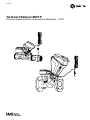
IMI Hydronic IMI-Hydronic 322231 TA-Smart BACnet Instrukcja obsługi
- Typ
- Instrukcja obsługi

1
01.2022
TA-Smart BACnet MS/TP
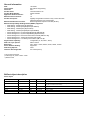
Protocol Implementation Conformance Statement – PICS

2
General information
Date: 18/11/2021
Vendor Name: IMI Hydronic Engineering
Vendor ID: 926
Product Name: TA-Smart DN32 to 80
Product Model Number: 322231-XXXXX
Application Software Version: 1.0
BACnet Protocol Revision: 16
Product Description: Digitallycongurableconnected2-waycontrolvalvewith
integratedultrasonicowmeasurement
BACnet Standard Device Prole: BACnetApplicationSpecicController(B-ASC)
BACnet Interoperability Building Blocks (BIBBs) supported:
• DataSharing-ReadProperty-B(DS-RP-B)
• DataSharing-ReadPropertyMultiple-B(DS-RPM-B)
• DataSharing-WriteProperty-B(DS-WP-B)
• DataSharing-WritePropertyMultiple-B(DS-WPM-B)
• DeviceManagement-DynamicDeviceBinding-B(DM-DDB-B)
• DeviceManagement-DynamicObjectBinding-B(DM-DOB-B)
• DeviceManagement-DeviceCommunicationControl-B(DM-DCC-B)†
• DeviceManagement-TimeSynchronization(DM-TS-B)*
• DeviceManagement-UTCTimeSynchronization(DM-UTC-B)*
Segmentation Capability: Congurable(Tx,Rx,Both**,None)
Data Link Layer Options: MS/TPmaster
Baud rates: Auto,9600**,19200,38400,56700,76800,115200
Device Address Binding: Supported
Networking Options: None
Character Sets Supported: ISO10646(UTF-8)
†) No password required
*) Valid range for years is 2000 – 2099
**) Default value
BACnet object description
Device object
Object type / address Name Access Value Description
Device ObjectID RW 0…4194303 ValuecomputedfromtheS/Nbydefault
Device Objectname RW 1to32char Bydefault:“TA-SmartXYYYYYYYY”(XbeingtheDNSizeandYYYYYYYY
beingthe8characterserialnumber)
Device Serial-number R YYYYYYYY 8characters
Device Max-master RW 1…127 Maximumvalueforthe“pollformaster”
Device Location RW 32charmax Emptybydefault
Device Objectdescription RW 32charmax Emptybydefault

3
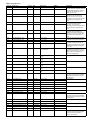
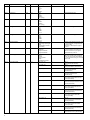
Object list (pages 3-7)
Obj type Object name Access Unit Value range Default Description
AI:0 ValveNominalFlow_unit1 R FlowUnit1 [0.0,3.4e+38] n.a. Nominalowofthevalveexpressedin
theunitsselectedinregistersFlowUnit1
andFlowUnit2respectively.Thisisthe
maximumvalueofowthatcanbe
assignedtothevalve.
AI:1 ValveNominalFlow_unit2 R FlowUnit2 [0.0,3.4e+38] n.a.
AI:2 ValveMinAdjustableFlow_unit1 R FlowUnit1 [0.0,3.4e+38] n.a. Minadjustableowofthevalve
expressedintheunitsselectedin
registersFlowUnit1andFlowUnit2
respectively.Thisistheminimumvalue
ofowthatcanbeassignedtothe
valve.
AI:3 ValveMinAdjustableFlow_unit2 R FlowUnit2 [0.0,3.4e+38] n.a.
AI:4 ValveNominalPower_unit1 R PowerUnit1 [0.0,3.4e+38] n.a. Nominalpowerofthevalveexpressed
intheunitsselectedinregisters
PowerUnit1andPowerUnit2
respectively.Thisisthemaximumvalue
ofpowerthatcanbeassignedtothe
valve.
AI:5 ValveNominalPower_unit2 R PowerUnit2 [0.0,3.4e+38] n.a.
AI:6 ValveMinAdjustablePower_
unit1
R PowerUnit1 [0.0,3.4e+38] n.a. Minadjustablepowerofthevalve
expressedintheunitsselectedin
registersPowerUnit1andPowerUnit2
respectively.Thisistheminimumvalue
ofpowerthatcanbeassignedtothe
valve.
AI:7 ValveMinAdjustablePower_
unit2
R PowerUnit2 [0.0,3.4e+38] n.a.
AI:8 ValveNominalStroke_mm R mm [0.0,3.4e+38] n.a. Nominalstrokeofthevalveexpressed
inmillimetersandinchesrespectively.
AI:9 ValveNominalStroke_inch R inch [0.0,3.4e+38] n.a.
AI:10 ValveMinAdjustableStroke_mm R mm [0.0,3.4e+38] n.a. Minadjustablestrokeofthevalve
expressedinmillimetersandinches
respectively.Thisistheminimumvalue
oflimitedstrokethatcanbeassigned
tothevalve.
AI:11 ValveMinAdjustableStroke_inch R inch [0.0,3.4e+38] n.a.
AI:12 AnalogSetPointValue R VDC or mA [0.0,10.0]forVDC;
[0.0,20.0]formA
n.a. AnaloginputvalueinVDCormAused
assetpointforcontrollingthevalveif
registerControlSourceissettoAnalog.
ValueisVDCormAdependingon
registerAnalogSignalType
AI:13 FlowSetPoint_unit1 R FlowUnit1 [0.0,ValveNominalFlow_
unit1]
n.a. Flowsetpoint
AI:14 FlowSetPoint_unit2 R FlowUnit2 [0.0,ValveNominalFlow_
unit2]
n.a.
AI:15 PowerSetPoint_unit1 R PowerUnit1 [0.0,ValveNominalPower_
unit1]
n.a. Powersetpoint
AI:16 PowerSetPoint_unit2 R PowerUnit2 [0.0,ValveNominalPower_
unit2]
n.a.
AI:17 PositionSetPoint_mm R mm [0.0,ValveNominalStroke_
mm]
n.a. Positionsetpoint
AI:18 PositionSetPoint_inch R inch [0.0,ValveNominalStroke_
inch]
n.a.
AI:19 RelativeMeasuredFlow R %[0.0,100.0] n.a. Measuredowexpressedin
percentageofthecurrentlyapplicable
maximumowdependingonregister
CurrentRegime
AI:20 MeasuredFlow_unit1 R FlowUnit1 [0.0,3.4e+38] n.a. Measuredow
AI:21 MeasuredFlow_unit2 R FlowUnit2 [0.0,3.4e+38] n.a.
AI:22 MeasuredSupplyTemp_degC R °C [-40.0,140.0] n.a. Measuredsupplytemperature
AI:23 MeasuredSupplyTemp_degF R °F [-40.0,284.0] n.a.
AI:24 MeasuredReturnTemp_degC R °C [-40.0,140.0] n.a. Measuredreturntemperature
AI:25 MeasuredReturnTemp_degF R °F [-40.0,284.0] n.a.
AI:26 MeasuredDeltaT_K R K [0.0,3.4e+38] n.a. MeasuredDeltaT
AI:27 MeasuredDeltaT_degF R °F [0.0,3.4e+38] n.a.
AI:28 RelativeMeasuredPower R %[0.0,100.0] n.a. Measuredpowerexpressedin
percentageofthecurrentlyapplicable
maximumpowerdependingonregister
CurrentRegime
AI:29 MeasuredPower_unit1 R PowerUnit1 [0.0,3.4e+38] n.a. Measuredpower
AI:30 MeasuredPower_unit2 R PowerUnit2 [0.0,3.4e+38] n.a.
AI:31 EnergyCounterRegime1_unit1 R EnergyUnit1 [0.0,3.4e+38] n.a. Energycounterinregime1
AI:32 EnergyCounterRegime1_unit2 R EnergyUnit2 [0.0,3.4e+38] n.a.
AI:33 EnergyCounterRegime2_unit1 R EnergyUnit1 [0.0,3.4e+38] n.a. Energycounterinregime2
AI:34 EnergyCounterRegime2_unit2 R EnergyUnit2 [0.0,3.4e+38] n.a.
AI:35 RelativeMeasuredPosition R %[0.0,100.0] n.a. Measuredpositionexpressedin
percentageofthecurrentlyapplicable
maximumpositiondependingon
registerCurrentRegime

4
Obj type Object name Access Unit Value range Default Description
AI:36 MeasuredPosition_mm R mm [0.0,3.4e+38] n.a. Measuredposition
AI:37 MeasuredPosition_inch R inch [0.0,3.4e+38] n.a.
AV:0 ControlCharCoecient R/W n.a. [0.01,0.99] 0.25 Thiscoecient(thermaleciency)
allowstoadjustthecurvatureofthe
EQMandInvertedEQMcharacteristics.
Defaultvalueis0.25.
AV:1 R1SetbackPercentage R/W %[0.0,100.0] 100.0 Setbackpercentageappliedto
MaxFlowRegime1whenCurrentRegime
issettoRegime1Setback
AV:2 R2SetbackPercentage R/W %[0.0,100.0] 100.0 Setbackpercentageappliedto
MaxFlowRegime2whenCurrentRegime
issettoRegime2Setback
AV:3 MaxFlowRegime1_unit1 R/W FlowUnit1 [ValveMinAdjustableFlow_
unit1,ValveNominalFlow_
unit1]
ValveNominalFlow_unit1 Maxowassignedtothevalvewhen
thevalveisinregime1
AV:4 MaxFlowRegime1_unit2 R/W FlowUnit2 [ValveMinAdjustableFlow_
unit2,ValveNominalFlow_
unit2]
ValveNominalFlow_unit2
AV:5 MaxFlowRegime2_unit1 R/W FlowUnit1 [ValveMinAdjustableFlow_
unit1,ValveNominalFlow_
unit1]
ValveNominalFlow_unit1 Maxowassignedtothevalvewhen
thevalveisinregime2
AV:6 MaxFlowRegime2_unit2 R/W FlowUnit2 [ValveMinAdjustableFlow_
unit2,ValveNominalFlow_
unit2]
ValveNominalFlow_unit2
AV:7 MinFlowRegime1_unit1 R/W FlowUnit1 [0.0,MaxFlowRegime1_
unit1]
0.0 Minowassignedtothevalvewhenthe
valveisinregime1
AV:8 MinFlowRegime1_unit2 R/W FlowUnit2 [0.0,MaxFlowRegime1_
unit2]
0.0
AV:9 MinFlowRegime2_unit1 R/W FlowUnit1 [0.0,MaxFlowRegime2_
unit1]
0.0 Minowassignedtothevalvewhenthe
valveisinregime2
AV:10 MinFlowRegime2_unit2 R/W FlowUnit2 [0.0,MaxFlowRegime2_
unit2]
0.0
AV:11 MaxPowerRegime1_unit1 R/W PowerUnit1 [ValveMinAdjustablePower_
unit1,ValveNominalPower_
unit1]
ValveNominalPower_
unit1
Maxpowerassignedtothevalvewhen
thevalveisinregime1
AV:12 MaxPowerRegime1_unit2 R/W PowerUnit2 [ValveMinAdjustablePower_
unit2,ValveNominalPower_
unit2]
ValveNominalPower_
unit2
AV:13 MaxPowerRegime2_unit1 R/W PowerUnit1 [ValveMinAdjustablePower_
unit1,ValveNominalPower_
unit1]
ValveNominalPower_
unit1
Maxpowerassignedtothevalvewhen
thevalveisinregime2
AV:14 MaxPowerRegime2_unit2 R/W PowerUnit2 [ValveMinAdjustablePower_
unit2,ValveNominalPower_
unit2]
ValveNominalPower_
unit2
AV:15 MaxPositionRegime1_mm R/W mm [ValveMinAdjustableStroke_
mm,ValveNominalStroke_
mm]
ValveNominalStroke_
mm
Maxpositionassignedtothevalve
whenthevalveisinregime1
AV:16 MaxPositionRegime1_inch R/W inch [ValveMinAdjustableStroke_
inch,ValveNominalStroke_
inch]
ValveNominalStroke_
inch
AV:17 MaxPositionRegime2_mm R/W mm [ValveMinAdjustableStroke_
mm,ValveNominalStroke_
mm]
ValveNominalStroke_
mm
Maxpositionassignedtothevalve
whenthevalveisinregime2
AV:18 MaxPositionRegime2_inch R/W inch [ValveMinAdjustableStroke_
inch,ValveNominalStroke_
inch]
ValveNominalStroke_
inch
AV:19 MinPositionRegime1_mm R/W mm [0.0,MaxPositionRegime1_
mm]
0.0 Minpositionassignedtothevalvewhen
thevalveisinregime1
AV:20 MinPositionRegime1_inch R/W inch [0.0,MaxPositionRegime1_
inch]
0.0
AV:21 MinPositionRegime2_mm R/W mm [0.0,MaxPositionRegime2_
mm]
0.0 Minpositionassignedtothevalvewhen
thevalveisinregime2
AV:22 MinPositionRegime2_inch R/W inch [0.0,MaxPositionRegime2_
inch]
0.0
AV:23 RelativeSetpoint R/W %[0.0,100.0] 100.0 Relativesetpointinpercentage
ofcurrentlyapplicablemaxvalue.
Thissetpointappliesifregister
ControlSourceissettoBus
AV:24 AdditiveConcentration R/W %[0.0,57.0] 0.0 Additiveconcentrationinwaterin%
weight.Additiveisdenedthrough
registerFluidType.Registerisnot
writableifFluidTypeisWater

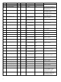
5
Obj type Object name Access Unit Value range Default Description
AV:25 OverrideValue_unit1 R/W [0.0,3.4e+38] Valueofthemaxow,powerorposition
thatappliesifregisterOverrideTypeis
setto1,2,4or6.Thevalueisexpressed
accordinginselectedUnit1forowand
powerandinmmforposition
AV:26 OverrideValue_unit2 R/W [0.0,3.4e+38] Valueofthemaxow,powerorposition
thatappliesifregisterOverrideTypeis
setto1,2,4or6.Thevalueisexpressed
accordinginselectedUnit2forowand
powerandininchforposition
AV:55 LastErrors[1] R n.a. [0,2^32] 0Newesterrorinerrorlog.Positivefor
raisederror,negativeforclearederror.
Descriptionpropertyisformattedas
follows:
+YYMMDD_HHMMSS_ShortErrorString
or
-YYMMDD_HHMMSS_ShortErrorString
SeeobjectBSV:0forthelistofpossible
errors
AV:... …
AV:59 LastErrors[10] R n.a. [0,2^32] 0Oldesterrorinerrorlog.Positivefor
raisederror,negativeforclearederror.
Descriptionpropertyisformattedas
follows:
+YYMMDD_HHMMSS_ShortErrorString
or
-YYMMDD_HHMMSS_ShortErrorString
SeeobjectBSV:0forthelistofpossible
errors
AV:60 LastEvents[1] R n.a. [0,2^32] 0Newesteventineventlog.
Descriptionpropertyisformattedas
follows:
YYMMDD_HHMMSS_ShortEventString
SeetableEventsforthelistofpossible
events
AV:… …
AV:69 LastEvents[10] R n.a. [0,2^32] 0Oldesteventineventlog.
Descriptionpropertyisformattedas
follows:
YYMMDD_HHMMSS_ShortEventString
SeetableEventsforthelistofpossible
events
MSI:0 ValveFamily R n.a. 1:TA-Smart
2:TA-Smart-Dp
n.a. Familytowhichthevalvebelongs
MSI:1 ValveVersion R n.a. 1:Standard n.a. Versionofthevalve
MSI:2 ValveSize R n.a. 3:DN20-3/4”
4:DN25-1”
5:DN32-1”1/4
6:DN40-1”1/2
7:DN50-2”
8:DN65-2”1/2
9:DN80-3”
10:DN100-4”
11:DN125-5”
n.a. Sizeofthevalve
MSI:3 AnalogSignalType Rn.a. 1:Voltage(VDC)
2:Current(mA)
1Denesthetypeofanaloginputsignal
assetbyjumperinsidetheSmartBox
MSV:0 FluidType R/W n.a. 1:Water
2:Monoethyleneglycol
3:Monopropyleneglycol
1Typeoftheuid.Itcanbeeitherwater
oroneofthelistedadditivesdilutedin
water
MSV:1 FlowSide R/W n.a. 1:Supplyside
2:Returnside
1Pipingsideonwhichthevalveis
installed(supplyorreturn)
MSV:2 ControlMode R/W n.a. 1:Flowcontrol
2:Powercontrol
4:Positioncontrol
1Thecontrolmodeindicateswhich
variableisbeingcontrolledbythevalve
MSV:3 ControlCharacteristics R/W n.a. 1:Linear
2:Equal-percentage
(EQM)
3:InvertedEQM
2Signalcharacteristicsappliedto
thesetpointvaluegiveninregister
RelativeSetpointintoatargetvaluefor
thecontrolledvariable.Whencontrol
modeissettoowcontrol,thechosen
characteristicsshouldbeselectedas
EQMandLinearintheothercases.
MSV:4 ControlSource R/W n.a. 1:Analog
2:Bus
1Controlsourcespecieswhetherthe
setpointforcontrollingthevalveis
providedbytheanaloginput(inwhich
casebusisusedjustformonitoring)or
bythebus
MSV:5 FlowUnit1 R/W n.a. 1:m3/h
2:l/s
3:l/min
4:l/h
5:GPM
1Firstselectedowunit

6
Obj type Object name Access Unit Value range Default Description
MSV:6 FlowUnit2 R/W n.a. 1:m3/h
2:l/s
3:l/min
4:l/h
5:GPM
5 Secondselectedowunit
MSV:7 PowerUnit1 R/W n.a. 1:kW
2:W
3:Btu/h
4:kBtu/h
5:ton(refrig.)
1Firstselectedpowerunit
MSV:8 PowerUnit2 R/W n.a. 1:kW
2:W
3:Btu/h
4:kBtu/h
5:ton(refrig.)
4 Secondselectedpowerunit
MSV:9 EnergyUnit1 R/W n.a. 1:kWh
2:kJ
3:MJ
4:kBtu
5:MBtu
6:ton.h
1Firstselectedenergyunit
MSV:10 EnergyUnit2 R/W n.a. 1:kWh
2:kJ
3:MJ
4:kBtu
5:MBtu
6:ton.h
5 Secondselectedenergyunit
MSV:11 RegimeSwitching R n.a. 1:None
2:Dual-rangeinputsignal
3:Bus
4:Temperaturedetection
5:Scheduling
1Switchingmodebetweenregimes1and
2.Tobechangedbycongurationwith
theHyTuneapp.
WhenNone,valuesinputforregime1
areused.
MSV:12 CurrentRegime R/W n.a. 1:Regime1
2:Regime2
3:Regime1Setback
4:Regime2Setback
1Currentchange-overregime.Changing
thecurrentchange-overregimevia
BACnetcanbedoneonlyifregister
RegimeSwitchingissetto2.
MSV:13 OverrideType R/W n.a. 1:None
2:Flow
3:Power
5:Valveposition
6:Stop
7:Simulatedoperation
1Typeofoverridedeningwhichactionis
takenasanoverridetothecongured
control.Thevalveresetsautomatically
tonormaloperationleavingtheoverride
after3hours.
BSV:0 CurrentErrorState R n.a. Bit0(0x01):0/1 0Error1:
ErrorLowPower(ELowPower)
Bit1(0x02):0/1 0Error2:
ErrorInputLineBroken(EInLnBreak)
Bit2(0x04):0/1 0Error3:
WarningFlowNotReached
(WFlowNotRchd)
Bit3(0x08):0/1 0Error4:
WarningPowerNotReached
(WPwrNotRchd)
Bit4(0x10):0/1 0Error5:
ErrorLocalTempSensorDisconnected
(ELclTmpSnsrDsctd)
Bit5(0x20):0/1 0Error6:
ErrorRemoteTempSensorDisconnected
(ERmtTmpSnsrDsctd)
Bit6(0x40):0/1 0Error7:
ErrorLocalTempSensorShortCircuit
(ELclTmpSnsrShrtC)
Bit7(0x80):0/1 0Error8:
ErrorRemoteTempSensorShortCircuit
(ERmtTmpSnsrShrtC)
Bit8(0x100):0/1 0Error9:
ErrorLocalTempSensorBelowMin
(ELclTmpSnsrBlw)
Bit9(0x200):0/1 0Error10:
ErrorRemoteTempSensorBelowMin
(ERmtTmpSnsrBlw)
Bit10(0x400):0/1 0Error11:
ErrorLocalTempSensorAboveMax
(ELclTmpSnsrAbv)
Bit11(0x800):0/1 0Error12:
ErrorRemoteTempSensorAboveMax
(ERmtTmpSnsrAbv)
Bit14(0x4000):0/1 0Error15:
ErrorFlowMeasurement(EFlowMsrmt)

7
Event table
Value Short event string Description
0x40000001 EvRstUsrDt Resettouserdefault
0x40000002 EvAdmnLogin LoginasAdmin
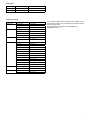
Object processing
Object type Optional properties Writable properties
AnalogInput MinPresValue PresentValue
MaxPresValue OutofService
Resolution
AnalogValue Description PresentValue
MinPresValue OutofService
MaxPresValue
Resolution
BitStringValue
BitText PresentValue
OutofService
Device Location ObjectIdentier
Description ObjectName
SerialNumber Location
Description
SegmentationSupported
MaxSegmentsAccepted
UTCOset
DaylightSavingsStatus
APDUSegmentTimeout
APDUTimeout
NumberofAPDURetries
MaxMaster
MaxInfoFrames
Multi-stateInput StateText PresentValue
OutofService
Multi-stateValue StateText PresentValue
OutofService
ThepropertiesObjectname,DescriptionandLocationofthe
DeviceObjectsupportupto32characters(allothercharacter
stringsareread-only).
ThedevicedoesnotsupporttheCreateObjectand
DeleteObjectservice.

8
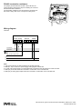
Wiring diagram
TA-Smart
Note:
1.A,BandMterminalsareNOTisolatedfromallotherterminals.
2.GND(M-0V)iscommontopowersupply,analogsignalsandRS485.
3.IncaseofACpowersupply,L24andMshouldbeconnectedtothesamephaseforeachTA-Smart.
4.GND(0V)ofRS485shouldbeconnectedto0VAC/VDConthecontrollerside.
5.GND(0V)ofanaloginput/outputshouldbeconnectedto0VAC/VDConthecontrollerside.
We reserve the right to introduce technical alterations without prior notice.
www.imi-hydronic.com
RS-485 termination resistance
ThejumperplacedbesidetheRS-485A,BandMwirecon-
nectorsmustbeclosed(settoON)foractivatingthe120Ohm
RS-485terminationresistance.
TheterminationresistancemustbeactivatedifTA-Smartisat
theendofadaisychainorifitisnotpartofadaisychain.
L24
M (0V)
Xv
M (0V)
Y
RX- (6)
RX+ (3)
TX- (2)
TX+ (1)
A
B
M (0V)
Y = 0-10V
Y = 0-20mA
RS485
Termination R
Contains Transmitter
Module FCC ID:
X8WBC840M
OFF
ON
L24M XvY
24 VAC/VDC
0 VAC/VDC
0(2)..10 VDC
0(2)..10 VDC or 0(4)..20 mA
AMB
RX- TX-RX+TX+
M
AnalogPower Ethernet RS485
A
B
RS 485
-
 1
1
-
 2
2
-
 3
3
-
 4
4
-
 5
5
-
 6
6
-
 7
7
-
 8
8


IMI Hydronic IMI-Hydronic 322231 TA-Smart BACnet Instrukcja obsługi
- Typ
- Instrukcja obsługi
w innych językach
Inne dokumenty
-
Fujitsu UTY-ABGX Instrukcja obsługi
-
-
Mettler Toledo 5000TOCi Sensor Instrukcja obsługi
-
Carrier 30AWH006HB Instrukcja instalacji
-
Tesy AquaThermica 260 S Instrukcja instalacji
-
 Key Automation 580ISCT-101 Instrukcja obsługi
-
 Beninca MATRIX and CP.BULL Instrukcja obsługi
-
 Beninca CP.BULL Instrukcja obsługi
-
 Beninca CP.B1024ESA Instrukcja obsługi
-
 Roger Technology B70/1DCHP control board Instrukcja obsługi


