
L8542678
12/2013 rev 3
CP.B24ESA
CP.B1024ESA
UNIONE NAZIONALE COSTRUTTORI
AUTOMATISMI PER CANCELLI, PORTE
SERRANDE ED AFFINI
CP.B24ESA CP.B1024ESA

2
LAMP
24Vdc
24Vdc
500mA max
- +
AUX1
AUX2
RADIO
BATTERY CHARGER
F1
+COM
P.P.
STOP
PHC
PHO
PED
BAR
BAR
AUX1
AUX1
BLINK
BLINK
+24V
-24V
N L
F2
MOT
L1
AUX
N1
L1
N1
0V
ANT
ANT
SHIELD
AUX2
AUX2
MOT
AUX
0V
COM
SWO
MOT
SWC
ENCODER
8k2
DAS
DAS
J1 DAS
Open
DAS N.C.
J1 DAS
Close
DAS 8K2
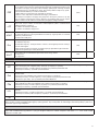
CP.B24 ESA CP.B1024 ESA CP.B24 ESA-A CP.B1024 ESA-A
F1 T2A
F2 T1A T2A T2A T4A
1

3
4
OPEN
OPEN
OPEN
OPEN
MINV:On
MINV:Off
2
3
SCA
AUX1:0
+COM
P.P.
STOP
PHOT
OPEN
CLOSE
BAR
BAR
AUX1
AUX1
BLINK
BLINK
+24V
-24V
SCA 24Vac
3W max
24Vac
500mA max
AUX1:1
II°CH RADIO
+COM
P.P.
STOP
PHOT
OPEN
CLOSE
BAR
BAR
AUX1
AUX1
BLINK
BLINK
+24V
-24V
AUX1:2
SERVICE/ZONE LIGHT
Service Light
AUX1:3
Zone Light
L N
Service/Zone
Light
230Vac
Relè 24Vac
P.P.
STOP
PHOT
OPEN
CLOSE
BAR
BAR
AUX1
AUX1
BLINK
BLINK
+24V
-24V
SCA
AUX2:0
SCA 24Vdc
3W max
24Vdc
1A max
AUX1
AUX1
BLINK
BLINK
+24V
-24V
AUX2
AUX2
AUX2:1
II°CH RADIO
AUX1
AUX1
BLINK
BLINK
+24V
-24V
AUX2
AUX2
SERVICE/ZONE LIGHT
L N
Service/Zone
Light
230Vac
Relè 24Vdc
AUX1
AUX1
BLINK
BLINK
+24V
-24V
AUX2
AUX2
AUX2:2
Service Light
AUX2:3
Zone Light

4
AVVERTENZE
Questo manuale è destinato esclusivamente a personale
qualificato per l’installazione e la manutenzione di aperture
automatiche.
Nessuna informazione qui presente è di interesse o di utilità
per l’utente finale.
Conservare questo manuale per futuri utilizzi.
L’installatore deve fornire tutte le informazioni relative
al funzionamento automatico, manuale e di emergenza
dell'automazione, e consegnare all’utilizzatore dell’impian-
to le istruzioni d’uso.
•
Prevedere sulla rete di alimentazione un inter-
ruttore/sezionatore onnipolare con distanza
d’apertura dei contatti uguale o superiore a 3 mm.
Verificare che a monte dell’impianto elettrico vi sia un interrut-
tore differenziale e una protezione di sovracorrente adeguati.
Alcune tipologie di installazione richiedono il collegamento
dell'anta ad un impianto di messa a terra rispondente alle
vigenti norme di sicurezza.
L’installazione elettrica e la logica di funzionamento devono
essere in accordo con le normative vigenti.
I conduttori alimentati con tensioni diverse, devono essere
fisicamente separati, oppure devono essere adeguata-
mente isolati con isolamento supplementare di almeno
1 mm.
I conduttori devono essere vincolati da un fissaggio sup-
plementare in prossimità dei morsetti.
Durante gli interventi di installazione, manutenzione e ri-
parazione, togliere l’alimentazione prima di accedere alle
parti elettriche.
Ricontrollare tutti i collegamenti fatti prima di dare ten-
sione.
Gli ingressi N.C. non utilizzati devono essere ponticellati.
Le descrizioni e le illustrazioni presenti in questo manuale
non sono impegnative. Lasciando inalterate le caratte-
ristiche essenziali del prodotto il fabbricante si riserva il
diritto di apportare qualsiasi modifica di carattere tecnico,
costruttivo o commerciale senza impegnarsi ad aggiornare
la presente pubblicazione.
Dichiarazione CE di Conformità
Dichiarazione in accordo alle Direttive 2004/108/CE(EMC); 2006/95/CE(LVD)
Fabbricante:
Automatismi Benincà SpA
Indirizzo:
Via Capitello, 45 - 36066 Sandrigo (VI) - Italia
Dichiara che il prodotto:
Centrale di comando per 1 motore 24Vdc, per cancelli scorrevoli:CP.B24ESA /CP.B1024ESA
è conforme alle condizioni delle seguenti Direttive CE:
• DIRETTIVA 2004/108/CE DEL PARLAMENTO EUROPEO E DEL CONSIGLIO del 15 dicembre 2004 concernente
il ravvicinamento delle legislazioni degli Stati membri relative alla compatibilità elettromagnetica e che abroga la direttiva
89/336/CEE, secondo le seguenti norme armonizzate:
EN 61000-6-2:2005, EN 61000-6-3:2007.
• DIRETTIVA 2006/95/CE DEL PARLAMENTO EUROPEO E DEL CONSIGLIO del 12 dicembre 2006 concernente il
ravvicinamento delle legislazioni degli Stati membri relative al materiale elettrico destinato ad essere adoperato entro taluni
limiti di tensione, secondo le seguenti norme armonizzate:
EN 60335-1:2002 + A1:2004 + A11:2004 + A12:2006 + A2:2006 + A13:2008; EN 60335-2-103:2003.
se applicabile:
• DIRETTIVA 1999/5/CE DEL PARLAMENTO EUROPEO E DEL CONSIGLIO del 9 marzo 1999 riguardante le ap-
parecchiature radio e le apparecchiature terminali di telecomunicazione e il reciproco riconoscimento della loro conformità,
secondo le seguenti norme armonizzate: ETSI EN 301 489-3 V1.4.1 (2002) + ETSI EN 301 489-1 V1.4.1 (2002) + ETSI EN
300 220-3 V1.1.1 (2000) + EN 60950-1 (2001)
Benincà Luigi, Responsabile legale.
Sandrigo, 05/07/2011.

5
CENTRALE DI COMANDO CP.B24 ESA / CP.B1024 ESA
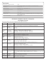
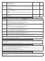
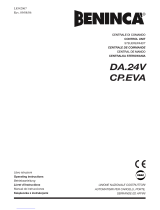
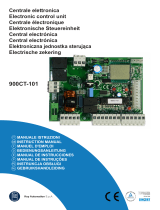
COLLEGAMENTI ELETTRICI
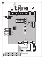
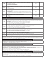
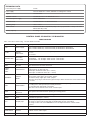
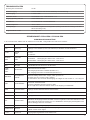
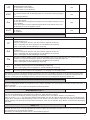
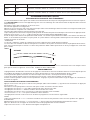
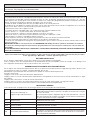
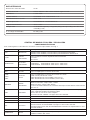
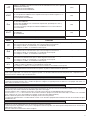
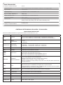
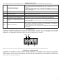
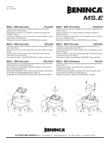
Nella seguente tabella sono descritti i collegamenti elettrici rappresentati in Fig. 1:
Morsetti Funzione Descrizione
L/N Alimentazione
Ingresso 230Vac 50/60Hz (L-Fase/N-Neutro) CP:B24ESA/CP-B1024ESA
Ingresso 115Vac 50/60Hz (L-Fase/N-Neutro) CP:B24ESA-A/CP-B1024ESA-A
L1/N1
Primario
Trasformatore
Connettore per il collegamento del primario trasformatore
L1: Linea
N1: Neutro
0V/MOT/
AUX
Secondario
Trasformatore
Connettore collegamento del secondario trasformatore
CP.B24ESA: 0V:Ingresso 0V - MOT:23 Vac - AUX:18 Vac
CP.B1024ESA: 0V:Ingresso 0V - MOT:30 Vac - AUX:18 Vac
MOT Motore Connettore rapido per il collegamento motore
ENC Encoder Connettore rapido per il collegamento encoder
COM
SWO
SWC
Finecorsa
Connettore rapido per il collegamento dei finecorsa.
COM:Comune per finecorsa
SWO:Ingresso finecorsa APRE (contatto N.C.)
SWC:Ingresso finecorsa CHIUDE (contatto N.C.)
BAR/BAR
COSTA
SICUREZZA
Ingresso contatto costa sensibile
Costa resistiva 8K2: Jumper “DAS” chiuso
Costa meccanica: Jumper “DAS” aperto
L’intervento della costa arresta il movimento dell’anta e inverte per circa 3s.
PED PEDONALE
Ingresso pulsante pedonale (contatto N.O.), comanda l’apertura parziale dell’anta, secondo il
valore impostato dal parametro TPED.
Attivo solo con cancello in completa chiusura.
Diventa ingresso “CHIUDE” con logica OPCL:ON o HTR:ON.
PHO Fotocellula Apre Ingresso fotocellula attiva in fase di apertura e chiusura
PHC Fotocellula Ingresso fotocellula attiva in fase di chiusura.
STOP STOP Ingresso pulsante STOP (contatto N.C.)
P.P. Passo-Passo
Ingresso pulsante passo-passo (contatto N.O.).
Assume la funzione di ingresso APRE se la logica OPCL=ON o HTR=ON.
Nel caso la logica HTR sia ON è VIETATO utilizzare l’ingresso con temporizzatori o altri sistemi
analoghi.
+COM COMUNE Comune per tutti gli ingressi di comando.
SHIELD/ANT Antenna
Collegamento antenna scheda radioricevente incorporata
SHIELD: Schermo / ANT: Segnale
+ 24V - 24 Vdc Uscita alimentazione accessori 24Vdc/500mA max.
DATI TECNICI
Alimentazione centrale di comando
24 Vdc
Alimentazione di rete
230 Vac 50/60 Hz oppure 115Vac 50/60Hz a seconda della versione
Uscita Motore
1 motore 24Vdc
Corrente massima
CP.B24ESA: 2.8 A - CP.B1024ESA: 3.5 A
Uscita alimentazione accessori
24Vdc 500mA max.
Grado di protezione
CP.B24ESA:IP30 - CP.B1024ESA:IP20
Temp. funzionamento
-20°C / +50°C
Ricevitore radio
433,92 MHz incorporato e confgurabile (rolling-code o fisso+rolling-code + ARC
Advanced Rolling Code)
N° codici memorizzabili
64 rolling-code

6
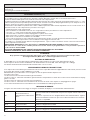
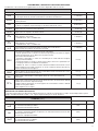
BLINK Lampeggiante Collegamento lampeggiante 24Vdc 15W max.
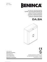
AUX1 AUX1
Contatto pulito (N.O.) configurabile tramite il parametro AUX1 come SCA (spia cancello aperto),
secondo canale radio, luce di cortesia o di zona (vedi Parametro AUX1).
AUX2 AUX2
Contatto pulito (N.O.) configurabile tramite il parametro AUX2 come SCA (spia cancello aperto),
secondo canale radio, luce di cortesia o di zona (vedi Parametro AUX2).
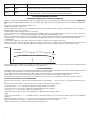
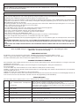
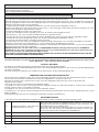
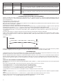
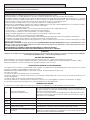
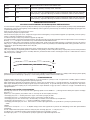
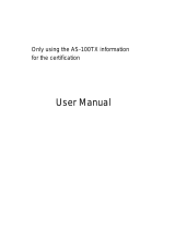
AUTOAPPRENDIMENTO QUOTE E
TARATURA DISPOSITIVO ANTISCHIACCIAMENTO
Dopo aver eseguito il montaggio dell’automazione i collegamenti elettrici e aver programmato tutte le funzioni richieste è OBBLIGATO-
RIO eseguire l’autoapprendimento delle quote e la taratura delle soglie di intervento del dispositivo antischiacciamento (amperometri-
ca).
Portarsi nel menu AUTO e premere il pulsante <PG>
Il display visualizza la scritta PUSH.
Premere nuovamente il pulsante <PG>, ha inizio la procedura di autotaratura: il display visualizza la scritta PRG, mentre vengono co-
mandate almeno 2 manovre complete.
Terminata la procedura il display visualizza la scritta OK.
La procedura può essere eseguita da qualsiasi posizione dell’anta e può essere interrotta in qualsiasi momento con la pressione simul-
tanea dei tasti <+> e <->, o con l’intervento degli ingressi STOP/PHO/PHC/DAS/OPEN/CLOSE.
Al termine della procedura di autoset i parametri PMO e PMC, se precedentemente modificati, vengono riportati ai valori di default*. Se
la procedura non ha esito positivo, viene visualizzato il messaggio ERR, verificare eventuali ostacoli o punti di attrito sull’anta.
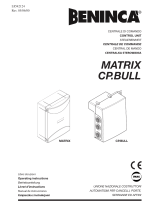
* ATTENZIONE!:
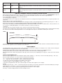
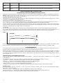
Il calcolo della coppia tiene conto delle variazioni di resistenza che oppone l’anta durante la manovra.
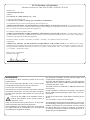
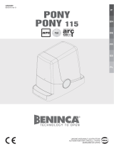
L’intera corsa viene suddivisa in 64 punti in apertura e 64 punti in chiusura la cui coppia ottimale di funzionamento viene letta e memo-
rizzata dalla centrale. I valori dei parametri PMO e PMC rappresentano un offset rispetto a quanto calcolato dalla centrale.
PMO/C %
OPEN
OPEN
CLOSE
40%
AUTOSET
Il valore default al 40% normalmente è sufficiente ad evitare falsi interventi, in ogni caso è necessario eseguire le prove di impatto previste
dalle normative vigenti e se necessario modificare i valori PMO e PMC.
PROGRAMMAZIONE
La programmazione delle varie funzionalità della centrale viene effettuata utilizzando il display LCD presente a bordo della centrale ed
impostando i valori desiderati nei menu di programmazione descritti di seguito.
Il menu parametri consente di impostare un valore numerico ad una funzione, in modo analogo ad un trimmer di regolazione.
Il menu logiche consente di attivare o disattivare una funzione, in modo analogo al settaggio di un dip-switch.
Altre funzioni speciali seguono i menu parametri e logiche e possono variare a seconda del tipo di centrale o revisione software.
UTILIZZO DEI PULSANTI DI PROGRAMMAZIONE
Premere il tasto <PG> per accedere al menù principale (PAR>>LOG>>RADIO>>...) che si possono così selezionare premendo i tasti +
e -.
Selezionare il menu principale con il tasto <PG> per accedere al menu di funzioni desiderato.
• Premendo il tasto <+> si scorre all’interno del menu funzioni dall’alto verso il basso
• Premendo il tasto <-> si scorre all’interno del menu funzioni dal basso verso l’alto.
• Premendo il tasto <PG> si può accedere alle eventuali impostazioni da modificare.
• Con i tasti <+> e <-> si possono modificare i valori impostati.
• Ripremendo il tasto <PG> il valore viene programmato, il display mostra il segnale “PRG”.
NOTE:
La pressione simultanea di <+> e <-> effettuata all’interno di un menu funzione consente di tornare al menu superiore senza apportare
modifiche.
Mantenere la pressione sul tasto <+> o sul tasto <-> per accelerare l’incremento/decremento dei valori.
Dopo un’attesa di 30s la centrale esce dalla modalità programmazione e spegne il display.
La pressione del tasto <-> a display spento equivale ad un impulso P.P.

7
PARAMETRI, LOGICHE E FUNZIONI SPECIALI
Nelle tabelle di seguito vengono descritte le singole funzioni disponibili nella centrale.
PARAMETRI (PAR)
MENU FUNZIONE
MIN-MAX-(Default)
MEMO
TCA
Tempo di chiusura automatica. Attivo solo con logica “TCA”=ON.
Al termine del tempo impostato la centrale comanda una manovra di chiusura.
1-240-(40s)
Tped
Regola lo spazio percorso dall’anta durante l’apertura parziale comandata dall’in-
gresso pedonale.
5-100-(20%)
tsm
Regola la durata della fase di rallentamento.
Il valore è espresso in percentuale sul valore complessivo della corsa.
0-100-(20%)
FSTS
Regola la velocità di apertura e chiusura. 20-99-(70)
sldS
Regola la velocità durante la fase di rallentamento. 20-99-(50)
PMo
Regola la soglia di intervento del dispositivo antischiacciamento* (sensore ampero-
metrico) durante la fase di apertura .
1: massima sensibilità - 99**: minima sensibilità
1-99-(40%)
PMC
Regola la soglia di intervento del dispositivo antischiacciamento* (sensore ampero-
metrico) durante la fase di chiusura.
1: massima sensibilità - 99**: minima sensibilità
1-99-(40%)
TLS
Attivo solo con parametro AUX1 o AUX2 impostato al valore 2.
Regola il tempo di attivazione della luce di servizio.
1-240-(60s)
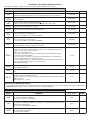
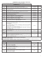
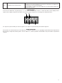
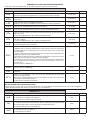
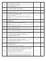
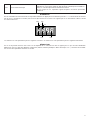
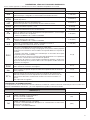
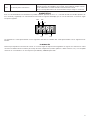
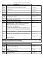
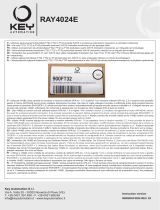
AUX1
Seleziona la modalità di funzionamento dell’uscita AUX1:
0: Spia cancello aperto. La spia è spenta a porta chiusa, lampeggia con porta in
movimento, è accesa con porta aperta.
Vedi schema di collegamento.
1: Secondo canale radio. L’uscita è controllata dal canale radio della ricevente
incorporata (vedi menu RADIO).
2: Luce di servizio. Il contatto si chiude per il tempo impostato con il parametro
TLS. Il conteggio inizia con l’inizio della manovra.
3: Luce di zona. Il contatto si chiude durante la manovra di apertura e resta chiuso
per tutto il tempo TCA e si riapre solo a porta chiusa.
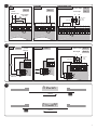
Vedi collegamenti figura 2.
0-3-(0)
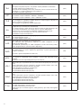
AUX2
Stesse opzioni di funzionamento dell’uscita AUX1, ma riferite ai morsetti AUX2.
Vedi collegamenti figura 3.
0-3-(1)
TBR
Regola lo spazio di arresto dopo l’intercettazione del finecorsa di chiusura e aper-
tura.
1-3-(3)
SPIN
Regola lo spazio di inversione che percorre l’anta a seguito di intervento del bordo
sensibile (o Intervento amperometrica).
Durante la fase di inversione sono ignorati ulteriori interventi del bordo sensibile o
delle fotocellule.
Valore espresso in secondi.
1-4 (2)
* ATTENZIONE: UN’ERRATA IMPOSTAZIONE DI QUESTI PARAMETRI PUÒ RISULTARE PERICOLOSA.
RISPETTARE LE NORMATIVE VIGENTI!
** Impostando il valore a 99 prima di effettuare l’Autotest la centrale non effettua il calcolo della coppia come indicato nel paragrafo
“APPRENDIMENTO QUOTE”, e il sensore amperometrico è di fatto disabilitato.
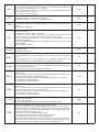
LOGICHE (LOGI)
MENU FUNZIONE
ON-OFF-(Default)
MEMO
TCA
Abilita o disabilita la chiusura automatica
On: chiusura automatica abilitata
Off: chiusura automatica disabilitata
(ON)
IBL
Abilita o disabilita la funzione condominiale.
On: funzione condominiale abilitata. L’impulso P.P. o del trasmettitore non ha effetto
durante la fase di apertura.
Off: funzione condominiale disabilitata.
(OFF)
IBCA
Abilita o disabilita i comandi PP durante la fase TCA.
On: Comandi PP non abilitati.
Off: Comandi PP abilitati.
(OFF)

8
SCL
Abilita o disabilita la chiusura rapida, attivabile solo se TCA:ON
On: chiusura rapida abilitata. Con cancello aperto l’intervento della fotocellula provoca
la chiusura automatica dopo 3 s.
Se l’intervento delle fotocellulla avviene durante la fase di apertura, la manovra viene
completata e dopo 3s viene comanda la chiusura
Off: chiusura rapida disabilitata.
(OFF)
PP
Seleziona la modalità di funzionamento del ”Pulsante P.P.” e del trasmettitore.
On: Funzionamento: APRE > CHIUDE > APRE >
Off: Funzionamento: APRE > STOP > CHIUDE > STOP >
(OFF)
PRE
Abilita o disabilita il pre-lampeggio.
On: Pre-lampeggio abilitato. Il lampeggiante si attiva 3s prima della partenza del
motore.
Off: Pre-lampeggio disabilitato.
(OFF)
HTR
Abilita o disabilita la funzione Uomo presente.
(La logica OPCL viene automaticamente abilitata)
On: Funzionamento Uomo Presente. L’ingresso Passo-Passo diventa ingresso APRE,
l’ingresso PED diventa ingresso CHIUDE.
La pressione simultanea di APRE e CHIUDE effettua lo STOP.
La pressione dei pulsanti APRE/CHIUDE deve essere mantenuta durante tutta la
manovra.
Off: Funzionamento automatico.
(OFF)
LTCA
Abilita o disabilita il lampeggiante durante il tempo TCA.
On: Lampeggiante attivo.
Off: Lampeggiante non attivo.
(OFF)
CVAR
Abilita o disabilita i trasmettitori a codice programmabile.
On: Ricevitore radio abilitato esclusivamente ai trasmettitori a codice variabile (rolling-
code).
Off: Ricevitore abilitato a trasmettitori codice variabile (rolling-code) e programmabile
(autoapprendimento e dip/switch) .
(OFF)
SOFT
Abilita o disabilita la partenza a velocità rallentata.
On: Esegue le partenze a velocità rallentata per poi passare a velocità normale.
Off: Partenza a velocità rallentata non attiva.
(ON)
OPCL
Abilita o disabilita l’ingresso PP come APRE e l’ingresso PED come CHIUDE.
On: Ingresso PP abilitato come APRE e ingresso PED abilitato come CHIUDE.
Off: ingresso PP e PED attivi con la propria funzione.
(OFF)
tst1
Attiva o disattiva la verifica della fotocellula collegata all’ingresso PHO.
Prima di effettuare la manovra di chiusura la centrale verifica la commutazione del
contatto della fotocellula (Attivo solo con ESA:ON).
Se la verifica ha esito negativo non viene avviata la manovra.
On: verifica fotocellule attivata
Off: verifica fotocellule disattivata
(OFF)
tst2
Attiva o disattiva la verifica della fotocellula collegata all’ingresso PHC
Prima di effettuare la manovra di chiusura la centrale verifica la commutazione del
contatto della fotocellula (Attivo solo con ESA:ON).
Se la verifica ha esito negativo non viene avviata la manovra.
On: verifica fotocellule attivata
Off: verifica fotocellule disattivata
(OFF)
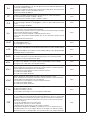
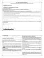
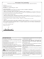
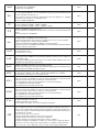
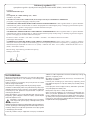
MINV
Seleziona il verso di apertura del motore (vedi Fig.4):
On: Motore installato a destra
Off: Motore installato a sinistra
Se si modifica questa logica è necessario ripetere l’AUTOSET.
(OFF)
esa
Attiva o disattiva la funzionalità di risparmio energetico “ESA”.
On: La centrale una volta terminata la manovra di apertura o chiusura, si pone nella
condizione di massima efficienza energetica, riducendo al minimo l’assorbimento,
disalimentando il trasformatore di potenza e le uscite accessori. Nota: la funzione
ESA non si attiva se:
- la scheda caricabatterie è in fase di ricarica
- la logica AUX2 è posta a 0 e l’anta è aperta.
- durante il tempo di attivazione luce di servizio se AUX2:2.
Off: Risparmio energetico disabilitato. Da utilizzare nel caso si desideri avere l’u-
scita alimentazione accessori sempre attivata, ad esempio se si utilizzano tastiere
alimentate a 24 Vdc, o altri dispositivi che necessitano di essere sempre alimentati.
(ON)

9
REM
Abilita o disabilita l’inserimento remoto dei radiotrasmettitori (vedi paragrafo AP-
PRENDIMENTO REMOTO).
On: Inserimento remoto abilitato
Off: Inserimento remoto disabilitato.
(ON)
TSTM
Abilita o disabilita la verifica dei motori.
On: Verifica abilitata. Se la verifica ha esito negativo non viene comandata nessuna
manovra.
Off: Verifica disabilitata.
(ON)
ENC
Abilita o disabilita l’encoder.
On: Encoder abilitato.
Off: Encoder abilitato. Funzionamento a tempo, apprendimento quote e autoset
non disponibile.
Se si attiva questa logica dopo averla disabillitata è necessario effettuare un nuovo
AUTOSET.
(ON)
THRM
Abilita o disabilita l’intervento protezione termica motore
On: abilitata
Off: disabilitata
(ON)
RADIO (RAD)
MENU FUNZIONE
PP
Selezionando questa funzione la ricevente si pone in attesa (Push) di un codice trasmettitore da assegnare alla funzione
passo-passo.
Premere il tasto del trasmettitore che si intende assegnare a questa funzione.
Se il codice è valido, viene memorizzato e viene visualizzato il messaggio OK
Se il codice non è valido, viene visualizzato il messaggio Err.
2Ch
Selezionando questa funzione la ricevente si pone in attesa (Push) di un codice trasmettitore da assegnare al secondo
canale radio. Premere il tasto del trasmettitore che si intende assegnare a questa funzione.
Se il codice è valido, viene memorizzato e viene visualizzato il messaggio OK
Se il codice non è valido, viene visualizzato il messaggio Err.
PED
Selezionando questa funzione la ricevente si pone in attesa (Push) di un codice trasmettitore da assegnare alla funzione
PED. Premere il tasto del trasmettitore che si intende assegnare a questa funzione.
Se il codice è valido, viene memorizzato e viene visualizzato il messaggio OK
Se il codice non è valido, viene visualizzato il messaggio Err.
CLR
Selezionando questa funzione la ricevente si pone in attesa (Push) di un codice trasmettitore da cancellare dalla memoria.
Se il codice è valido, viene cancellato e viene visualizzato il messaggio OK
Se il codice non è valido o non è presente in memoria, viene visualizzato il messaggio Err
RTR
Cancella completamente la memoria della ricevente. Viene richiesta conferma dell’operazione.
Nota: Non possono essere memorizzati contemporaneamente trasmettitori ARC e Rolling-code/Codice fisso. Se il primo trasmettitore
memorizzato è ad esempio ARC, successivi trasmettitori potranno essere solo ARC. Utilizzare la funzione RTR per azzerare comple-
tamente la memoria nel caso si desideri cambiare tipologia di trasmettitori.
NUMERO MANOVRE (Nman)
Visualizza il numero di cicli completi (apre+chiude) effettuate dall’automazione.
La prima pressione del pulsante <PG>, visualizza le prime 4 cifre, la seconda pressione le ultime 4.
Es. <PG> 0012 >>> <PG> 3456: effettuati 123.456 cicli.
CICLI MANUTENZIONE (maci)
Questa funzione consente di attivare la segnalazione di richiesta manutenzione dopo un numero di manovre stabilito dall’installatore.
Per attivare e selezionare il numero di manovre, procedere come segue:
Premere il pulsante <PG>, il display viusalizza OFF, che indica che la funzione è disabilitata (valore di default).
Con i pulsanti <+> e <-> selezionare uno dei valori numerici proposti (da OFF a 100). I valori vanno intesi come centinaia di cicli di
manovre (ad es.: il valore 50 sta ad indicare 5000 manovre).
Premere il pulsante OK per attivare la funzione. Il display visualizza il messaggio PROG.
La richiesta di manutenzione viene segnalata all’utente con il protrarsi del lampeggio del lampeggiante a fine manovra di circa 10s.
RESET (RES)
RESET della centrale. ATTENZIONE!: Riporta la centrale ai valori di default.
La prima pressione del pulsante <PG> provoca il lampeggio della scritta RES, una ulteriore pressione del pulsante <PG> effettua il
reset della centrale.
Nota: Non vengono cancellati i trasmettitori dalla ricevente, ne la posizione e la corsa dell’anta.

10
AUTOSET (AUTO)
Esegue l’apprendimento della corsa dell’automazione e la taratura delle soglie di intervento del dispositivo antischiacciamento (am-
perometrica).
Vedi paragrafo AUTOAPPRENDIMENTO
PASSWORD DI ACCESSO (CODE)
Consente di inserire un codice di protezione di accesso alla programmazione della centrale.
E’ possibile inserire un codice alfanumerico di quattro caratteri utilizzando i numeri da 0 a 9 e le lettere A-B-C-D-E-F.
Il valore di default è 0000 (quattro zeri) e indica l’assenza di codice di protezione.
In qualsiasi momento è possibile annullare l’operazione di inserimento del codice, premendo contemporaneamente i tasti + e -. Una
volta inserita la password è possibile operare sulla centrale, entrando ed uscendo dalla programmazione per un tempo di circa 10
minuti, in modo da consentire le operazioni di regolazione e test delle funzioni.
Sostituendo il codice 0000 con qualsiasi altro codice si abilita la protezione della centrale, impedendo l’accesso a tutti i menu. Se si
desidera inserire un codice di protezione, procedere come segue:
- selezionare il menu Code e premere PG.
- viene visualizzato il codice 0000, anche nel caso sia già stato inserito in precedenza un codice di protezione.
- con i tasti + e - si può variare il valore del carattere lampeggiante.
- con il tasto OK si conferma il carattere lampeggiante e si passa al successivo.
- dopo aver inserito i 4 caratteri compare un messaggio di conferma “CONF”.
- dopo alcuni secondi viene ri-visualizzato il codice 0000
- è necessario riconfermare il codice di protezione precedentemente inserito, in modo da evitare inserimenti involontari.
Se il codice corrisponde al precedente, viene visualizzato un messaggio di conferma “OK”
La centrale esce automaticamente dalla fase di programmazione, e per accedere nuovamente ai menu sarà necessario inserire il
codice di protezione memorizzato.
IMPORTANTE: ANNOTARE il codice di protezione e CONSERVARLO IN LUOGO SICURO per future manutenzioni.
Per rimuovere un codice da una centrale protetta è necessario entrare in programmazione con la password e riportare il
codice al valore di default 0000.
IN CASO DI SMARRIMENTO DEL CODICE È NECESSARIO RIVOLGERSI ALL’ASSISTENZA
TECNICA AUTORIZZATA, PER IL RESET TOTALE DELLA CENTRALE.
ATTENZIONE:
Dopo qualsiasi variazione apportata alle logiche o reset della centrale è necessario eseguire una procedura
di autoapprendimento (Menu Auto - vedi Autoapprendimento Quote)
BATTERIA DI EMERGENZA
E’ disponibile un accessorio opzionale per l’alimentazione della centrale in caso di assenza di alimentazione di rete.
Il kit è composto da una scheda caricabatteria e da due batterie da 12V ricaricabili, staffe di fissaggio, viti e cablaggi.
Per utlteriori informazioni fate riferimento alle istruzioni fornite con l’accessorio.
APPRENDIMENTO REMOTO TRASMETTITORI
Se si dispone di un trasmettitore già memorizzato nella ricevente è possibile effettuare l’apprendimento radio remoto (senza necessità
di accedere alla centrale). La logica REM deve essere ON.
IMPORTANTE: La procedura deve essere eseguita con ante in apertura durante la pausa TCA.
Procedere come segue:
1 Premere il tasto nascosto del trasmettitore già memorizzato.
2 Premere, entro 5s, il tasto del trasmettitore già memorizzato corrispondente al canale da associare al nuovo trasmettitore. Il lampeg-
giante si accende.
3 Premere entro 10s il tasto nascosto del nuovo trasmettitore.
4 Premere, entro 5s, il tasto del nuovo trasmettitore da associare al canale scelto al punto 2. Il lampeggiante si spegne.
5 La ricevente memorizza il nuovo trasmettitore ed esce immediatamente dalla programmazione.
MESSAGGI DI ERRORE
Di seguito sono elencati alcuni messaggi che vengono visualizzati dal display in caso di anomalie di funzionamento:
err
Errore autotaratura o
apprendimento radiotrasmet-
titore
Se l’errore si presenta in fase di autoapprendimento controllare lo stato degli in-
gressi PP/STOP/PHC/PHO/PED/BAR o la presenza di punti di attrito nella corsa
dell’anta.
Se l’errore si presenta in fase di apprendimento dei radiotrasmettitori, significa
che la memoria della ricevente non può ricevere altri trasmettitori o che il trasmet-
titore non è compatibile.
Err1
Errore motore Verificare collegamenti motore
Err2
Errore fotocellule Verificare collegamenti fotocellule
Err5
Errore encoder Verificare collegamenti encoder
Err7
Errore bordo sensibile Verificare collegamenti e funzionamento del bordo sensibile

11
amp
Intervento amperometrica
Un ostacolo o un punto di attrito ha provocato l’intervento del sensore amperto-
metrico. Rimuovere l’ostacolo o verificare la corsa dell’anta. Eventualmente inter-
venire sul parametro PMO/PMC.
THRM
Interevento termico
La centrale ha messo in condizione di riposo l’automazione a seguito di un nume-
ro eccessivo di manovre consecutive. Trascorso un tempo sufficiente al raffreda-
mento la centrale riprende il normale funzionamento.
Se ciò non avviene potrebbe trattarsi di un guasto al motore che ne richiede la
sostituzione.
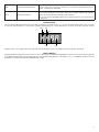
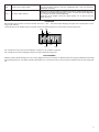
DIAGNOSTICA
Nel caso di anomalie di funzionamento è possibile visualizzare, premendo il tasto + o -, lo stato di tutti gli ingressi (finecorsa, comando
e sicurezza). Ad ogni ingresso è associato un segmento del display che in caso di attivazione si accende, secondo il seguente schema.
PHO
SWC
STOP
SWO
PHC
DAS
P.P. PED
Gli ingressi N.C. sono rappresentati dai segmenti verticali. Gli ingressi N.O. sono rappresentati dai segmenti orizzontali.
SMALTIMENTO
Qualora il prodotto venga posto fuori servizio, è necessario seguire le disposizioni legislative in vigore al momento per quanto riguarda
lo smaltimento differenziato ed il riciclaggio dei vari componenti (metalli, plastiche, cavi elettrici, ecc.); è consigliabile contattare il vostro
installatore o una ditta specializzata ed abilitata allo scopo.

12
WARNINGS
This manual has been especially written to be use by
qualified fitters.
None of the information provide in this manual can be
considered as being of interest for the end users.
Preserve this manual for future needs.
The technician has to furnish all the information related to
the step by step function, the manual and the emergency
function of the operator, and to deliver the manual to the
final user.
•
Foresee on the supply net an onnipolar switch or
selector with distance of the contacts equal or
superior to 3 mms.
Verify that of the electrical system there is an awry diffe-
rential interrupter and overcurrent protection.
Some typologies of installation require the connection of
the shutter to be link at a conductive mass of the ground
according to the regulations in force.
The electrical installation and the operating logic must
comply with the regulations in force.
The leads fed with different voltages must be physically
separate, or they must be suitably insulated with additional
insulation of at least 1 mm.
The leads must be secured with an additional fixture near
the terminals.
During installation, maintenance and repair, interrupt the
power supply before opening the lid to access the elec-
trical parts
Check all the connections again before switching on the
power.
The unused N.C. inputs must be bridged.
The descriptions and the present illustrations in this manual
are not binding. Leaving the essential characteristics of the
product unchanged, the manufacturer reserves himself
the right to bring any change of technical, constructive
or commercial character without undertaking himself to
update the present publication.
EC Declaration of Conformity
Pursuant to Directives 2004/108/CE(EMC); 2006/95/CE(LVD)
Manufacturer:
Automatismi Benincà SpA.
Address:
Via Capitello, 45 - 36066 Sandrigo (VI) – Italy
It is hereby stated that the item:
Control unit for 1 24VDC for sliding gates:CP.B24ESA /CP.B1024ESA
it is compliant with provisions of the following other EC Directives:
• DIRECTIVE 2004/108/EC OF THE EUROPEAN PARLIAMENT AND OF THE COUNCIL of 15 December 2004, on
the harmonisation of the laws of Member States relating to electromagnetic compatibility and which cancels Directive 89/336/
EEC, according to the following harmonised regulations:
EN 61000-6-2:2005, EN 61000-6-3:2007.
• DIRECTIVE 2006/95/EC OF THE EUROPEAN PARLIAMENT AND OF THE COUNCIL of 12 December 2006, on
the harmonisation of the laws of Member States relating to electrical equipment designed for use with certain voltage limits,
according to the following harmonised regulations:
EN 60335-1:2002 + A1:2004 + A11:2004 + A12:2006 + A2:2006 + A13:2008; EN 60335-2-103:2003.
if applicable:
• DIRECTIVE 1999/5/EC OF THE EUROPEAN PARLIAMENT AND OF THE COUNCIL of 9 March 1999 on radio
equipment and telecommunications terminal equipment and the mutual recognition of their conformity, according to the fol-
lowing harmonised standards: ETSI EN 301 489-3 V1.4.1 (2002) + ETSI EN 301 489-1 V1.4.1 (2002) + ETSI EN 300 220-3
V1.1.1 (2000) + EN 60950-1 (2001)
Benincà Luigi, Legal Ofcer.
Sandrigo, 05/07/2011.

13
CONTROL PANEL CP.B24 ESA / CP.B1024 ESA
WIRE DIAGRAM
Wire connections shown in Fig. 1 are described hereunder:
Terminals Function Description
L/N Power supply
Input, 230VAC 50/60 Hz (L-Phase/N-Neutral) CP:B24ESA/CP-B1024ESA
Input, 115VAC 50/60 Hz (L-Phase/N-Neutral) CP:B24ESA/CP-B1024ESA-A
L1/N1
Primary
Transformer
Connector for the connection of the primary transformer
L1: Line
N1: Neutral
0V/MOT/AUX
Secondary
Transformer
Connector for the connection of the secondary transformer
CP.B24ESA: 0V: 0V Input - MOT:23 VAC - AUX:18 VAC
CP.B1024ESA: 0V: 0V Input - MOT:30 VAC - AUX:18 VAC
MOT Motor Fast connector for motor connection
ENC Encoder Fast connector for encoder connection
COM
SWO
SWC
Limit Switches
Rapid connector for the connection of limit switches.
COM:Common for limit switches
SWO:Input, OPEN limit switch (N.C. contact)
SWC:Input, CLOSE limit switch (N.C. contact)
BAR/BAR
SAFETY
EDGE
Input: sensitive safety edge
8K2 resistive safety edge: closed “DAS” jumper
Mechanical safety edge: open “DAS” jumper
When the safety edge is activated, the gate leaf stops and its movement is reversed for around
3 seconds.
PED PEDESTRIAN
Pedestrian push-button intput (N.O. contact). The gate partial opening is controlled
according to the value preset by the TPED parameter.
It is activated only with totally closed gate.
With OPCL:ON or HTR:ON, it becomes “CLOSE” input.
PHO
Open
Photocell
Input, photocell activated in both opening and closing phases
PHC Photocell Input, photocell is activated in the closing phase.
STOP STOP STOP button input (N.C. contact)
P.P. Step by step
Input, Step-by-Step push-button (Normally Open contact)
If the logics is OPCL=ON or HTR=ON, the OPEN input function is provided.
If the logics HTR is ON, it is FORBIDDEN to use the input with timers or other similar
systems.
+COM COMMON Common for all control inputs.
SHIELD/ANT antenna
Connection antenna to the built-in receiver
SHIELD: Screen / ANT: Signal
+ 24V - 24 Vdcs Accessories power supply 24Vdc/500mA max.
TECHNICAL DATA
Contol unit power supply
24 Vdc
Power supply
230 Vac 50/60 Hz or 115Vac 50/60Hz according to the version
Output
1 motor 24Vdc
Maximum current:
CP.B24ESA: 2.8 A - CP.B1024ESA: 3.5 A
Accessories power supply
24Vdc 500mA max.
Protection level
CP.B24ESA:IP30 - CP.B1024ESA:IP20
Operating temp.
-20°C / +50°C
Radio receiver
built in 433,92 MHz confgurabile (rolling-code or programmable + rolling-code+ ARC
Advanced Rolling Code)
Memory capacity
64 rolling-code transmitters

14
BLINK Flashing Connection to flashing light 24Vdc 15W max.
AUX1 AUX1
Normally open (N.O.), clean contact, which is configurable like SCA (open gate indicator
light) through parameter AUX1, second radio channel, courtesy or area light (see Parameter
AUX 1).
AUX2 AUX2
Normally open (N.O.), clean contact, which is configurable like SCA (open gate indicator
light) through parameter AUX2, second radio channel, courtesy or area light (see Parameter
AUX 2).
RUN SELF-LEARNING AND ANTI-CRUSHING DEVICE SETTING
After carrying out the wire connections of the automatic system and programming all functions required, it is MANDATORY to carry out
the self-learning of dimensions and the calibration of intervention thresholds of the anti-crash device (amperometrics).
Access the AUTO menu and press the <PG> push-button.
The wording PUSH is displayed.
Press the push-button <PG> again and self-calibration will start: the wording PRG is displayed while at least 2 complete operations are
carried out.
At the end of procedure, OK will be displayed.
The procedure can be carried out from any position of the gate leaf and can be interrupted at any moment by pressing the <+> and <->
keys at the same moment, or with the triggering of STOP/PHO/PHC/DAS/OPEN/CLOSE inputs.
At the end of self-setting, the PMO and PMC parameters, if previously modified, are shown as default values. If the procedure is not
successful, the wording ERR appears. Check that no obstacles or frictions are present.
*CAUTION!:
The torque value also includes changes in the resistance of the door during movement.
The entire stroke is divided in 64 opening points and 64 closing points where the optimal operating torque is read and memorised by
the control unit. The PMO and PMC parameters are an offset figure with respect to calculations made by the control unit.
PMO/C %
OPEN
OPEN
CLOSE
40%
AUTOSET
The default value at 40% is normally enough to avoid false interventions. In any case, if PMO and PMC should be modified, the impact
tests set out by regulations in force will have to be carried out.
PROGRAMMING
The programming of the various functions of the control unit is carried out using the LCD display on the control unit and setting the
desired values in the programming menus described below.
The parameters menu allows you to assign a numerical value to a function, in the same way as a regulating trimmer.
The logic menu allows you to activate or deactivate a function, in the same way as setting a dip-switch.
Other special functions follow the parameters and logic menus and may vary depending on the type of control unit or the software
release.
USE OF PROGRAMMING KEYS
Press <PG> key to gain access to the Main Menu (PAR>>LOG>>RADIO>>...). These keys can be selected by pressing + and – keys.
Select the Main menu with <PG> key to enter the desired Function Menu .
• If <+> is pressed, the Function Menu can be scrolled from top to bottom.
• If <-> is pressed, the Function Menu can be scrolled from bottom to top.
• If <PG> key is pressed, presetting to be modified can be entered.
• The preset values can be modified by using <+> and <-> keys.
• The value is programmed if <PG> key is pressed again. The word “PRG” appears on the display.
NOTES:
Simultaneously pressing <+> and <-> from inside a function menu allows you to return to the previous menu without making any changes.
Hold down the <+> key or the <-> key to accelerate the increase/decrease of the values.
After waiting 30s the control unit quits programming mode and switches off the display.
Pressing <-> with the display turned off means an impulse of P.P.

15
PARAMETERS, LOGIC AND SPECIAL FUNCTIONS
In the charts following the single available functions are described in the plant.
PARAMETERS (PAR)
MENU FUNCTION
MIN-MAX-(Default)
MEMO
TCA
Automatic closure time. It is enabled only with “TCA”=ON logic.
At the end of the preset time, the control unit controls a closure operation.
1-240-(40s)
Tped
The stroke time of the gate leaf is adjusted during the partial opening phase controlled
by the pedestrian input.
5-100-(20%)
tsm
Braking is adjusted.
The value is expressed in percentage on the aggregate value of the stroke.
0-100-(20%)
FSTS
The opening and closing speed is adjusted. 20-99-(70)
sldS
Speed during braking is adjusted. 20-99-(50)
PMo
Adjustment of amperometric sensor sensitivity in opening*
1: maximum sensibility - 99**: minimum sensibility
1-99-40%)
PMC
Adjustment of amperometric sensor sensitivity in closing*
1: maximum sensibility - 99**: minim sensibility
1-99-(40%)
TLS
It is activated only with AUX1 or AUX2 parameter preset on value 2.
The activation time of the service light is adjusted.
1-240-(60s)
AUX1
It selects the operating mode of the AUX 1 output:
0: Open gate indicator light. The light is off when the door is closed, flashes with
moving door and is on with open door.
See wire diagram.
1: Second radio channel. The output is controlled by the radio channel of the built-in
receiver (see RADIO Menu).
2: Service light. The contact closes for the time preset with TLS parameter. The
countdown starts at the inception of operation.
3: Area light. The contact closes in the opening phase and remains closed for the
entire TCA time. It opens only with closed door.
See wire diagram, Fig. 2.
0-3-(0)
AUX 2
The same operating options as AUX1 output, but referred to AUX2 terminals. See
connections in Fig. 3.
0-3-(1)
TBR
Stop space is adjusted after reaching the opening and closing limit switch. 1-3-(3)
SPIN
It regulates the reversal space that the leaf runs as consequence a result of the safety
edge action (or
triggering of the amperometric sensor)
.
During the reversal phase any further action of safety edge or photocells is ignored.
This value is expressed in second.
1-4 (2)
* ATTENTION: A wrong formulation of these parameters can be dangerous.
Respect the regulations in force!
** By presetting the value at 99 before carrying out the Autotest, the control unit does perform the calculation of the torque, as
indicated in paragraph "LEARNING OF VALUES", and the amperometric sensor is disabled.
LOGICS (LOGI)
MENU FUNCTION DEAFULT MEMO
TCA
Enables or disables automatic closing
On: automatic closing enabled
Off: automatic closing disabled
(ON)
IBL
Enables or disables multi-flat function.
On: multi-flat function enabled. The step-by-step and perdestrian commands have
no effect during the opening phase.
Off: multi-flat function disabled.
(OFF)
IBCA
During the TCA phase, the PP controls are enabled or disabled.
On: PP controls are disabled.
Off: PP controls are enabled.
(OFF)

16
SCL
The rapid closure is enabled or disabled. It can be activated only if TCA:ON
On: enabled rapid closure. With open gate, the photocell activation causes the
automatic closure after 3 s.
If the photocell is activated during the opening phase, the operation is completed
and closure starts after 3s
Off: disabled rapid closure.
(OFF)
PP
The operating mode of “P.P. Push button” and of the transmitter are selected.
On: Operation : OPEN > CLOSE > OPEN >
Off: Operation: OPEN > STOP > CLOSE > STOP >
(OFF)
PRE
Forewarning flashing light enabled or disabled.
On: enabled forewarning flashing light. The flashing light is activated 3 s before the
starting of the motor.
Off: disabled forewarning flashing light.
(OFF)
HTR
The Service Man function is enabled or disabled.
(The OPCL logics is automatically enabled).
On: Service Man operation. The Step-by-Step input becomes OPEN input, the PED
input becomes CLOSE input.
If the OPEN and CLOSE keys are pressed at the same time, the system will STOP.
The OPEN/CLOSE push buttons should be kept pressed for the entire operating
time.
Off: Automatic operation.
(OFF)
LTCA
During the TCA time, the blinker is enabled or disabled.
On: Enables blinker.
Off: Disables blinker.
(OFF)
CVAR
The code programmable transmitters is enabled or disabled.
On: Radio receiver enabled only for rolling-code transmitters.
Off: Receiver enabled for rolling-code and programmable code transmitters (self-
learning and Dip Switch).
(OFF)
SOFT
Soft start is enabled or disabled.
On: Starting is performed at reduced speed and then movement is restored to normal
speed.
Off: Soft start is disabled.
(ON)
OPCL
PP input as OPEN and PED input as CLOSED are enabled or disabled.
On: PP input is enabled as OPEN and PED input is enabled as CLOSED.
Off: PP and PED inputs are enabled with their function.
(OFF)
tst1
The checks on the photocell connected to PHO input are activated or deactivated.
Before carrying out the closing operation, the control unit checks that the photocell
contact has switched (this function is activated only with ESA:ON).In the negative,
the operation will not start.
On: check on photocells is activated
Off: check on photocells is deactivated
(OFF)
tst2
Checking on the photocell connected to PHC input is activated or deactivated.
Before carrying out the closing operation, the control unit checks that the photocell
contact has switched (this function is activated only with ESA:ON). In the negative,
the operation will not start.
On: checking on photocells is activated
Off: checking on photocells is deactivated
(OFF)
minv
Select the opening direction of the motor (see Fig. 4 ):
On: Right side motor mount
Off: Left side motor mount
If this logics is modified, this SELFTESTING will have to be repeated.
(OFF)
ESA
The ESA” energy savings function is activated or deactivated.
On: After completion of the opening or closing operations, the control unit switches
to the energy saving mode, while reducing current consumption to the minimum and
cutting off power from the transformed and the accessory outputs. Note: The ESA
function does not activate if:
- the battery recharge module is being recharged
- the AUX2 logics is on 0 and the gate leaf is open.
- during activation the service light if AUX2 is on 2.
Off: disabled energy savings. This is to be used should the accessory power supply
output is to be always activated, e.g. if keypads powered at 24VDC or other devices
that need to be always powered, are used.
(ON)

17
REM
The remote storage of the radio transmitter codes is enabled or disabled (see par.
REMOTE LEARNING).
On: Enabled remote storage
Off: Disabled remote storage.
(ON)
TSTM
The motor checks are enabled or disabled.
On: Checks are enabled. If the checks are not successful, the door/gate will not
move.
Off: Disabled check.
(ON)
ENC
The Encoder is enabled or disabled.
On: the encoder is enabled.
Off: the encoder is enabled. Timed operation, self-learning and self-setting are not
avvilable.
If this logics is activated after being disabled, a new SELFTEST should be carried
out.
(ON)
THRM
Enables or disables motor thermal protection intervention
On: enabled
Off: disabled
(ON)
RADIO (RAD)
MENU FUNCTION
PP
By selecting this function, the receiver is waiting for (Push) a transmitter code to be assigned to the step-by-step
function.
Press the transmitter key, which is to be assigned to this function.
If the code is valid, it will be stored in memory and OK will be displayed.
If the code is not valid, the Err message will be displayed.
2Ch
By selecting this function, the receiver is waiting for (Push) a transmitter code to be assigned to the second radio
channel.
Press the transmitter key, which is to be assigned to this function.
If the code is valid, it will be stored in memory and OK will be displayed.
If the code is not valid, the Err message will be displayed.
PED
When this function is selected, the receiver awaits (Push) a transmitter code to be assigned to the PED function.
Press the transmitter key, which is to be assigned to this function.
If the code is valid, it will be stored in memory and OK will be displayed.
If the code is not valid, the Err message will be displayed.
CLR
By selecting this function, the receiver is waiting for (Push) a transmitter code to be erased from memory.
If the code is valid, it will be stored in memory and OK will be displayed.
If the code is not valid, the Err message will be displayed.
RTR
The memory of the receiver is entirely erased. Confirmation for the operation is asked.
Note: Transmitters ARC and Rolling-code/Fixed code cannot be stored in memory at the same time. For example, if the first
transmitter stored in memory is ARC, the following transmitters could be only ARC. Use the RTC function to completely erase the
memory should the type of transmitters be changed.
NUMBER OF CYCLES (Nman)
The number of cycles (open+close) completed by the system is displayed.
When the push-button <PG> is pressed once, the first 4 digits are displayed, if the push-button is pressed once more, the last 4
digits are displayed.
E.g. <PG> 0012 >>> <PG> 3456: 123.456 cycles were performed.
MAINTENANCE (maci)
This function allows to activate the indication of maintenance required after a certain number of operations, preset by the installer.
To activate and select the number of operations, proceed as follows:
Press the <PG> button, OFF is displayed, indicating that the function is disabled (default).
Select one of the numbers shown (from OFF to 100) by using the <+> and <-> keys . The figures express the value of hundreds of
cycles (e.g.: the number 50 means 5000 operations).
Press OK to activate the function. The PROG message is displayed.
When the flashing light flashes for around 10 sec at end of operation, this means that maintenance operations are needed.
RESET (RES)
RESET of the control unit. WARNING: Returns the control unit to the default values.
When the <PG> push-button is pressed once, the RES wording begins to flash, if the push-button<PG> is pressed once more, the
control unit is reset.
Note: neither the transmitter codes nor the position and stroked of the gate leaf will be erased from the receiver.

18
AUTOSET (AUTO)
The self-calibration of the triggering thresholds of the anti-crash device (amperometric sensor), as well as the stroke learning are peri-
formed. See paragraph SELF-LEARNING
PASSWORD (CODE)
It allows to type in an access protection code to the programming of the control unit.
A four-character alphanumeric code can be typed in by using the numbers from 0 to 9 and the letters A-B-C-D-E-F.
The default value is 0000 (four zeros) and shows the absence of a protection code.
While typing in the code, this operation can be cancelled at any moment by pressing keys + and – simultaneously. Once the password
is typed in, it is possible to act on the control unit by entering and exiting the programming mode for around 10 minutes in order to
allow adjustments and tests on functions.
By replacing the 0000 code with any other code, the protection of the control unit is enabled, thus preventing the access to any other
menu. If a protection code is to be typed in, proceed as follows:
- select the Code menu and press OK.
- the code 0000 is shown, also in the case a protection code has been previously typed in.
- the value of the flashing character can be changed with keys + and -.
- press OK to confirm the flashing character, then confirm the following one.
- after typing in the 4 characters, a confirmation message “CONF” appears.
- after a few seconds, the code 0000 appears again
- the previously stored protection code must be reconfirmed in order to avoid any accidental typing in.
If the code corresponds to the previous one, a confirmation message “OK” appears.
The control unit automatically exits the programming phase. To gain access to the Menus again, the stored protection code must be
typed in.
IMPORTANT: TAKE NOTE of the protection code and KEEP IT IN A SAFE PLACE for future maintenance operations. To remove
the code from a protected control unit, enter the programming mode with the password and reset the code to the 0000 default
value.
IF YOU LOOSE THE CODE, PLEASE CONTACT THE AUTHORISED SERVICE CENTER FOR THE TOTAL RESET OF THE CON-
TROL UNIT.
ATTENTION:
After any LOGIC change or control panel reset, it is necessary to perform a self-learning procedure
(Menu Auto - See Stroke self learning)
EMERGENCY BATTERY
An optional accessory to power the control unit is available in the event the mains power supply is cut off.
The kit is composed of a battery charger and two 12V rechargeable batteries, fixing brackets, screws and cables.
For further information, please refer to instructions supplied with the accessory.
TRANSMITTER REMOTE LEARNING
If the transmitter code is already stored in the receiver, the remote radio learning can be carried out (without accessing the control unit).
The REM logics must be ON.
IMPORTANT: The procedure should be carried out with gate in the opening phase, during the TCA dwell time.
Proceed as follows:
1 Press the hidden key of the transmitter, the code of which has already been stored in memory.
2 Within 5 seconds, press the already memorised transmitter key corresponding to the channel to be matched to the new transmitter.
The flashing light switches on.
3 Within 10 seconds, press the hidden key of the new transmitter.
4 Within 5 seconds, press the key of the new transmitter to be matched to the channel selected at item 2. The flashing light switches off.
5 The receiver stores the new transmitter code and exits from the programming mode immediately.
ERROR MESAGES
Some messages that are displayed in the event of malfunctions are shown hereunder:
err
Error, radiotransmitter self-adjustment
or
self-learning
If the error occurs during self-learning, check the STOP/PHOTO/PP/CLOSE in-
puts or whether frictions occur during the door leaf stoke.
If the error occurs during self-learning of the radio-transmitters, this means that
the memory of the receiver is no longer able to receive other transmitters or the
transmitter is not compatible.
Err1
Error, motor Check connections to the motor
Err2
Error, photocells Check connections to photocells
Err5
Error, encoder Check connections to the encoder
Err7
Error, sensitive safety edge Check connections and the operation of the sensitive safety edge
amp
Triggering of the amperometric sensor
An obstacle or a point of friction has caused the triggering of the amperometric
sensor. Remove the obstacle or check the door stroke. Act on the PMO/PMC
parameter, if required.

19
THRM
Triggering of the thermal switch
The control unit has switched the system to a rest status due to an excessive
number of consecutive operations. If a sufficient cooling time has elapsed, the
control unit is reset to normal operation.
In the negative, a fault in the motor might have occurred, which requires the
replacing of the motor.
DIAGNOSTICS
In the event of malfunctions, by pressing key + or - the status of all inputs (limit switches, control and safety) can be displayed. One
segment of the display is linked to each input. In the event of failure it switches on according to the following scheme.
PHO
SWC
STOP
SWO
PHC
DAS
P.P. PED
N.C. inputs are represented by the vertical segments. N.O. inputs are represented by the horizontal segments.
WASTE DISPOSAL
If the product must be dismantled, it must be disposed according to regulations in force regarding the differentiated waste disposal and
the recycling of components (metals, plastics, electric cables, etc..). For this operation it is advisable to call your installer or a specialised
company.

20
HINWEISE
Dieses Handbuch ist ausschließlich qualifiziertem Perso-
nal für die Installation und Wartung von automatischen
Öffnungsvorrichtungen bestimmt.
Es enthält keine Informationen die für den Endbenutzer
interessant oder nützlich sein könnten.
Bewahren Sie dieses Handbuch für Nachschlagzwecke
auf.
Der Installateur hat dem Benutzer alle Informationen über
den automatischen, manuellen und Not-Betrieb der Auto-
matik zusammen mit der Bedienungsanleitung zu liefern.
•
Das Stromnetz muss mit einem allpoligen Schalter
bzw. Trennschalter ausgestattet sein, dessen Kon-
takte einen Öffnungsabstand gleich oder größer
als 3 aufweisen.
Kontrollieren ob der elektrischen Anlage ein geeigneter
Differentialschalter und ein Überspannungsschutzschalter
vorgeschaltet sind. Einige Installationstypologien verlangen
den Anschluss des Flügels an eine Erdungsanlage laut den
geltenden Sicherheitsnormen.
Die elektrische Installation und die Betriebslogik müssen
den geltenden Vorschriften entsprechen.
Die Leiter die mit unterschiedlichen Spannungen gespeist
werden, müssen physisch getrennt oder sachgerecht mit
einer zusätzlichen Isolierung von mindestens 1 mm isoliert
werden.
Die Leiter müssen in der Nähe der Klemmen zusätzlich
befestigt werden.
Während der Installation, der Wartung und der Reparatur,
die Anlage stromlos machen bevor an den elektrischen
Teilen gearbeitet wird.
Alle Anschlüsse nochmals prüfen, bevor die Zentrale mit
Strom versorgt wird.
Die nicht verwendeten N.C. Eingänge müssen überbrückt
werden.
Die in diesem Handbuch enthaltenen Beschreibungen
und Abbildungen sind nicht verbindlich. Ausgenommen
der Haupteigenschaften des Produkts, behält sich der
Hersteller das Recht vor eventuelle technische, konstru-
ktive oder kommerzielle Änderungen vorzunehmen ohne
dass er vorliegende Veröffentlichung auf den letzten Stand
bringen muss.
EG-Konformitätserklärung
Erklärung gemäß Richtlinie 2004/108/CE(EMV); 2006/95/CE(LVD)
Hersteller:
Automatismi Benincà SpA
Adresse:
Via Capitello, 45 - 36066 Sandrigo (VI) - Italien
Erklärt, dass das Produkt:
Steuereinheit für 1 Motor zu 24Vdc für Schiebetore: CP.B24ESA /CP.B1024ESA
folgenden EG-Richtlinien entspricht:
• RICHTLINIE 2004/108/EG DES EUROPÄISCHEN PARLAMENTS UND DES RATES vom 15. Dezember 2004 zur
Angleichung der Rechtsvorschriften der Mitgliedstaaten über die elektromagnetische Verträglichkeit und zur Aufhebung der
Richtlinie 89/336/EWG, gemäß nachstehenden Normen:
EN 61000-6-2:2005, EN 61000-6-3:2007.
• RICHTLINIE 2006/95/EG DES EUROPÄISCHEN PARLAMENTS UND DES RATES vom 12. Dezember 2006 zur An-
gleichung der Rechtsvorschriften der Mitgliedstaaten betreffend elektrische Betriebsmittel zur Verwendung innerhalb bestimmter
Spannungsgrenzen, gemäß nachstehenden Normen:
EN 60335-1:2002 + A1:2004 + A11:2004 + A12:2006 + A2:2006 + A13:2008; EN 60335-2-103:2003.
Falls anwendbar:
• RICHTLINIE 1999/5/EG DES EUROPÄISCHEN PARLAMENTS UND DES RATES vom 9. März 1999 über Funkan-
lagen und Telekommunikationsendeinrichtungen und die gegenseitige Anerkennung ihrer Konformität, gemäß nachstehenden
Normen: ETSI EN 301 489-3 V1.4.1 (2002) + ETSI EN 301 489-1 V1.4.1 (2002) + ETSI EN 300 220-3 V1.1.1 (2000) + EN
60950-1 (2001)
Benincà Luigi, Rechtsvertreter
Sandrigo, 05/07/2011.
Strona się ładuje...
Strona się ładuje...
Strona się ładuje...
Strona się ładuje...
Strona się ładuje...
Strona się ładuje...
Strona się ładuje...
Strona się ładuje...
Strona się ładuje...
Strona się ładuje...
Strona się ładuje...
Strona się ładuje...
Strona się ładuje...
Strona się ładuje...
Strona się ładuje...
Strona się ładuje...
Strona się ładuje...
Strona się ładuje...
Strona się ładuje...
Strona się ładuje...
Strona się ładuje...
Strona się ładuje...
Strona się ładuje...
Strona się ładuje...
Strona się ładuje...
Strona się ładuje...
Strona się ładuje...
Strona się ładuje...
Strona się ładuje...
Strona się ładuje...
Strona się ładuje...
Strona się ładuje...
-
 1
1
-
 2
2
-
 3
3
-
 4
4
-
 5
5
-
 6
6
-
 7
7
-
 8
8
-
 9
9
-
 10
10
-
 11
11
-
 12
12
-
 13
13
-
 14
14
-
 15
15
-
 16
16
-
 17
17
-
 18
18
-
 19
19
-
 20
20
-
 21
21
-
 22
22
-
 23
23
-
 24
24
-
 25
25
-
 26
26
-
 27
27
-
 28
28
-
 29
29
-
 30
30
-
 31
31
-
 32
32
-
 33
33
-
 34
34
-
 35
35
-
 36
36
-
 37
37
-
 38
38
-
 39
39
-
 40
40
-
 41
41
-
 42
42
-
 43
43
-
 44
44
-
 45
45
-
 46
46
-
 47
47
-
 48
48
-
 49
49
-
 50
50
-
 51
51
-
 52
52


Beninca CP.B24ESA Instrukcja obsługi
- Typ
- Instrukcja obsługi
- Niniejsza instrukcja jest również odpowiednia dla
w innych językach
- español: Beninca CP.B24ESA Manual de usuario
- italiano: Beninca CP.B24ESA Manuale utente
- Deutsch: Beninca CP.B24ESA Benutzerhandbuch
- français: Beninca CP.B24ESA Manuel utilisateur
- English: Beninca CP.B24ESA User manual
Powiązane artykuły
-
 Beninca Matrix Operating Instructions Manual
-
 Beninca CP.BULL Instrukcja obsługi
-
 Beninca CP.B24 Instrukcja obsługi
-
 Beninca SCRD Instrukcja obsługi
-
 Beninca DA.24V Operating Instructions Manual
-
Beninca Heady Instrukcja obsługi
-
 Beninca MATRIX and CP.BULL Instrukcja obsługi
-
 Beninca MSE instrukcja
-
 Beninca DA.BA Operating Instructions Manual
-
 Beninca PONY Instrukcja obsługi


Inne dokumenty
-
DEA NET724 EVO Instrukcja obsługi
-
 Key Automation 580ISCT-101 Instrukcja obsługi
-
Key Gates Eclipse Instrukcja obsługi
-
-
-
Nice Mindy A400 Instrukcja obsługi
-
-
 Aleph AS-100RX Instrukcja obsługi
-
 Key Automation 580ISRAY4024 Instrukcja obsługi
-
Hama 85014111 Instrukcja obsługi


