
U s er ’ s ma n u a l
For devices with firmware version 1.4.4
6000 series IP recorders

All rights reserved © AAT SYSTEMY BEZPIECZEŃSTWA Sp. z o.o.
2
6000 series IP recorders - User’s manual - version 3.2
PRELIMINARY INFORMATION
This instruction manual contains detailed information concerning the operation of the 6000
series IP recorders.
PRELIMINARY INFORMATION
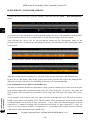
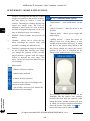
Pictures in this publication showing camera views can be simulations. Actual camera
images may vary depending on the type, model, settings, observation area, or
environmental conditions.
The company AAT SYSTEMY BEZPIECZEŃSTWA Sp. z o.o. has made every effort to
ensure that the information contained in this publication is comprehensive, accurate and
current.
However, due to the continuous development of the product line, graphic design, menu
layout or function descriptions contained in this publication may differ from those
implemented in your device. This does not limit or void this manual.
The following chapters describe all the functionalities present in the 6000 series IP
recorders. However, depending on your recorder model and/or firmware version, some of
the functions may be unavailable or not supported.
Technical data of the recorder, construction description, disk mounting method, first start
of the recorder and basic operation are included in the “Quick Start Guide” attached to
the recorder. When using this “User's Manual”, always have a quick start guide nearby so
that you can refer to it in matters not described in the user’s manual.

All rights reserved © AAT SYSTEMY BEZPIECZEŃSTWA Sp. z o.o.
3
6000 series IP recorders - User’s manual - version 3.2
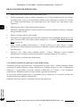
SHORTCUTS
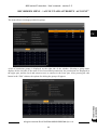
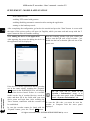
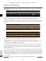
Auxiliary monitor output (Secondary output).
The SPOT auxiliary monitor output is inactive by default (i.e. it does not display any images). To
display an image on it, you must configure a view or sequence for this output. The configuration of
the auxiliary monitor output is described in “Output Settings” menu on page 67.
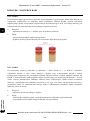
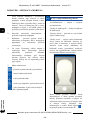
Detection, recognition and comparison of faces.
The recorder configuration for face comparison is a multi-step process. To properly configure this
option should be:
• Enable and configure face detection ( “Face Recognition” menu on page 32)
• Configure response options for face detection ( "Detection - Trigger Mode" submenu on
page 33)
• Configure face comparison options ( "Recognition" submenu on page 33)
• Configure face base ( “Face database management” menu on page 84)
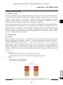
Creating disk arrays.
In recorders that allow mounting several disks, it is possible to build a disk array. Creating a disk
array allows you to increase reliability and fault tolerance. Creating a disk array is described in the
“Disk” menu on page 52 and in the “Array” menu on page 54. A description of the individual types
of RAID arrays is provided in the appendix “RAID Arrays” on page 109.
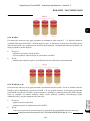
Archiving of recordings.
Recordings from the recorder can be archived on external media. The recorder provides AVI and
Private formats for archiving. To ensure the safety of recordings, it is recommended to use the Private
format. For more information on archiving recordings, see the appendix “Archiving of recordings”
on page 115.
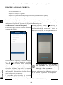
Mobile application.
The recorder allows access to recordings remotely, using a smartphone with a mobile application. For
the description of the application, see the appendix “Mobile application” on page 121.
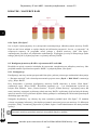
Detection, recognition and comparison of license plates.
The configuration of the recorder for the comparison of license plates also requires several stages of
preparation. To properly configure this option should be:
• Enable and configure license plate detection ( “LPR” menu on page 37)
• Configure response options for license plate detection ( "Recognition" submenu on page 38)
• Configure license plate database ( “License plate database management” menu on page 87)

All rights reserved © AAT SYSTEMY BEZPIECZEŃSTWA Sp. z o.o.
4
6000 series IP recorders - User’s manual - version 3.2
1. Recorder's main window ........................................................................................ 6
1.1. Left mouse button menu ................................................................................... 6
1.2. Right mouse button menu ................................................................................. 7
1.2.1. Camera management menu ........................................................................ 7
1.2.2. Change the resolution of the main monitor output ...................................... 8
2. „Start” menu .......................................................................................................... 9
3. ”Settings” menu ...................................................................................................... 9
3.1. „Camera” menu ........................................................................................... 10
3.1.1. “Manage Camera” settings group ............................................................. 10
3.1.2. “Add Camera” settings group .................................................................. 11
3.1.3. “Image” settings group ............................................................................ 13
3.1.4. “Motion Settings” settings group ............................................................. 14
3.1.5. “PTZ” settings group ............................................................................... 15
3.1.6. PTZ control menu .................................................................................... 20
3.1.7. Methods of controlling the movement of the PTZ camera head................ 22
3.2. “Record” menu ............................................................................................. 22
3.2.1. “Record” settings group ........................................................................... 22
3.2.2. “Encode Parameters” settings group ........................................................ 26
3.2.3. “Record status” settings group ................................................................. 27
3.3. “AI / Event” menu ....................................................................................... 28
3.3.1. “Event Notification” settings group ......................................................... 28
3.3.2. “AI Event” settings group ........................................................................ 31
3.3.2.1."Face recognition" menu ................................................................ 32
3.3.2.2."License plate recognition" menu ................................................... 37
3.3.2.3. „People/Vehicle Perimeter Detection” menu ................................. 41
3.3.2.4."More" menu .................................................................................. 43
3.3.3. “General Event” settings group ................................................................ 48
3.3.4. “Alarm Status” settings group.................................................................. 51
3.4. “Disk” menu ................................................................................................. 52
3.4.1. “Disk Management” settings group.......................................................... 52
3.4.2. “Storage Mode” settings group ................................................................ 55
3.4.3. “Disk” settings group .............................................................................. 56
3.5. “Network” menu .......................................................................................... 56
3.5.1. “Network” settings group ........................................................................ 56
3.5.2. “Stream Settings” settings group ............................................................. 60
3.5.3. “Network Status” settings group .............................................................. 60
3.6. “Account and Authority” menu .................................................................. 61
3.6.1. “Account” settings group ......................................................................... 61
3.6.2. “Security” settings group ......................................................................... 65
3.6.3. “User Status” settings group .................................................................... 66
3.7. “System” menu ............................................................................................ 66
3.7.1. “Basic” settings group ............................................................................. 66
3.7.2. “Maintenance” settings group .................................................................. 69
3.7.3. “Information” settings group ................................................................... 70
4. “Search and Backup” menu ................................................................................. 71
4.1. “By Time-sliced Image” settings group ...................................................... 71
4.2. “By Time” settings group ........................................................................... 74
TABLE OF CONTENTS

All rights reserved © AAT SYSTEMY BEZPIECZEŃSTWA Sp. z o.o.
5
6000 series IP recorders - User’s manual - version 3.2
4.3. “By Event” settings group ............................................................................. 75
4.4. “Tag Management” settings group ................................................................. 77
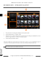
4.5. “Image Management” settings group ............................................................. 77
4.6. “Backup Status” settings group ...................................................................... 78
5. “Playback” menu ................................................................................................. 79
6. “Intelligent Analytics” menu ............................................................................... 84
6.1. “Sample Database” settings group ................................................................. 84
Face database management ............................................................................ 84
License plate database management ............................................................... 87
6.2. “Search” settings group ................................................................................. 88
6.3. “Statistics” settings group .............................................................................. 97
6.4. „Face Attendance” settings group .................................................................. 98
6.5. „Face Check In” settings group ...................................................................... 99
7. Recorder operation using the browser .............................................................. 100
7.1. Minimal PC configuration for browser connections ..................................... 100
7.2. Network connection via browser .................................................................. 100
7.3. Live display panel ........................................................................................ 101
7.4. “Playback” menu ......................................................................................... 106
7.5. “Search and Backup” menu .......................................................................... 107
7.6. “Intelligent Analysis” menu ......................................................................... 108
7.7. “Function Panel” menu ................................................................................ 108
8. Supplement - RAID disk arrays......................................................................... 109
8.1. General information ..................................................................................... 109
8.2. RAID levels ................................................................................................. 109
8.2.1. RAID 0 .................................................................................................. 109
8.2.2. RAID 1 .................................................................................................. 110
8.2.3. RAID 5 .................................................................................................. 110
8.2.4. RAID 6 .................................................................................................. 111
8.2.5. RAID 10 (1+0) ...................................................................................... 111
8.2.6. „Hot Spare” disk. .................................................................................. 112
8.3. RAID configuration in 6000 series IP recorders ........................................... 112
8.31. Configuration ......................................................................................... 112
8.3.2. Rebuilding the disk array ...................................................................... 113
8.3.3. Estimated recovery time for the RAID array ......................................... 114
8.3.4. Procedure with the RAID array in case of damage of the recorder ......... 115
9. Supplement - Archiving of recordings ............................................................... 115
9.1. Archiving of recordings on a USB drive ...................................................... 115
9.2. Moving and playing back the archive on a PC ............................................. 116
9.3. Player options .............................................................................................. 119
10. Supplement - mobile application ...................................................................... 121
10.1. Installation and initial configuration .......................................................... 121
10.2. Adding the device to the application .......................................................... 122
10.3. Basic operation .......................................................................................... 123
10.3.1. Landscape mode .................................................................................. 123
10.3.2. Portrait mode ....................................................................................... 123
10.3.2.1. Application configuration menu ................................................... 124
10.3.2.2. Remote playback menu ................................................................ 125
10.3.2.3. Additional menu options .............................................................. 126
TABLE OF CONTENTS

6000 series IP recorders - User’s manual - version 3.2
All rights reserved © AAT SYSTEMY BEZPIECZEŃSTWA Sp. z o.o.
6
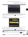
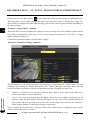
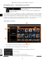
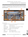
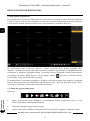
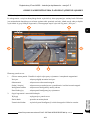
1. Recorder’s main window
After starting the recorder and logging in, the window for observing images from cameras will be
displayed on the monitor. The main elements of this window are described in the short manual
attached to the recorder, here other options, not mentioned in the short manual, will be described.
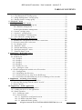
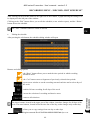
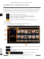
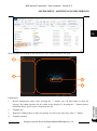
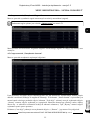
After starting, the camera image observation window displays empty viewing areas. The number of
areas and the division depends on the recorder model and display settings. After adding cameras to the
recorder, the images will be displayed in the preview areas. Adding can be done by going to the "Add
Camera" menu, or by pressing the symbol visible in the empty display area, which is a shortcut to
this menu.
After adding cameras to the viewing areas, each will have two menus for camera management. The
menu is displayed by pressing the left and right mouse buttons, respectively. The number and type of
options in each menu depends on the camera parameters.
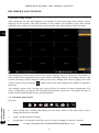
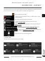
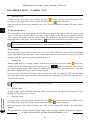
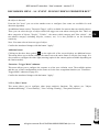
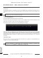
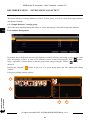
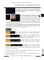
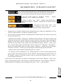
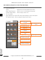
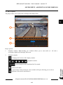
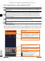
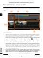
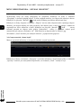
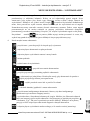
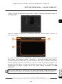
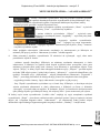
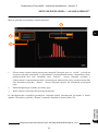
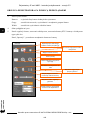
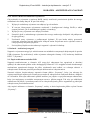
1.1. Left mouse button menu
From left:
• menu moving area. Clicking and holding the left mouse button in this place allows you to
change the position of the menu
• enable / disable manual recording
• fast playback. Clicking the icon allows you to view the recordings for the last 5 minutes
RECORDER'S MAIN WINDOW

6000 series IP recorders - User’s manual - version 3.2
All rights reserved © AAT SYSTEMY BEZPIECZEŃSTWA Sp. z o.o.
7
• enables / disables audio from the camera
• clicking the icon takes a photo (screenshot) of the selected channel. A new window will open,
which allows you to export the photo or save it to the NVR disk
• PTZ control icon. Clicking on the icon displays a simplified PTZ control menu (basic functions
only):
• digital zoom icon. Clicking opens a full screen preview where you can select the location and
degree of magnification. The zoom level can be changed using the appropriate buttons or the
mouse wheel.
• camera image settings icon. Clicking opens the full-screen preview and the image settings
control panel. The number of setting options depends on the camera parameters.
• enables / disables the audio to the camera
• activates the camera event view panel. Clicking opens a full-screen preview and a panel that
displays the current VCA events of the camera.
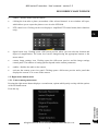
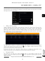
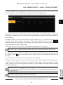
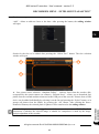
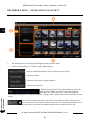
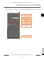
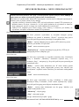
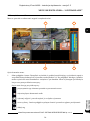
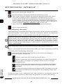
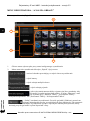
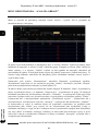
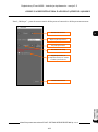
1.2. Right mouse button menu
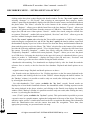
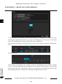
1.2.1. Camera management menu
Pressing the right mouse button displays a second menu, options which partly overlap with the options
of the left button menu.
From the top:
RECORDER'S MAIN WINDOW

6000 series IP recorders - User’s manual - version 3.2
All rights reserved © AAT SYSTEMY BEZPIECZEŃSTWA Sp. z o.o.
8
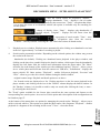
• Manually Record: enables / disables manual recording
• Instant Playback: enables fast playback. This option is analogous to the option of the left mouse
button, but it is possible to change the playback time in the range from 5 seconds to 5 minutes
(predefined), or the user can define the playback time himself ("Customization" option)
• Enable Audio: enables / disables audio from the camera
• Original Proportions / Overspread Window: change the preview display: original aspect ratio or
fit to the window
• Snapshot: takes a photo (screenshot)
• PTZ Control: enables the PTZ control panel. Clicking opens the full screen preview and the PTZ
control panel. Description of the panel functions can be found in chapter 2.1.6. PTZ Control
Menu on page 20.
• Zoom In: clicking opens a full screen preview where you can select the location and degree of
magnification. The zoom level can be changed using the appropriate buttons or the mouse
wheel.
• Target Detection: enables the camera event viewer panel. Clicking opens a full-screen preview
and a panel that displays the current VCA events of the camera.
• Camera info: displays the information window
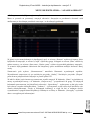
1.2.2. Change the resolution of the main monitor output
Pressing the right mouse button for about 5 seconds changes the image resolution of the main monitor
output. The change takes place in a loop, and each time you press and hold the button, the resolution
changes to the next one from the list of available resolutions. The change is confirmed with an
acoustic signal.
In this way, it is possible to obtain an image in the case when, for example, the monitor attached to the
recorder does not support the currently set resolution.
Clicking can take place anywhere in the main window.
RECORDER'S MAIN WINDOW

6000 series IP recorders - User’s manual - version 3.2
All rights reserved © AAT SYSTEMY BEZPIECZEŃSTWA Sp. z o.o.
9
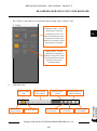
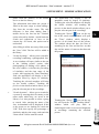
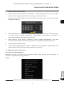
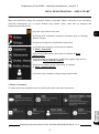
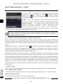
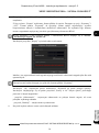
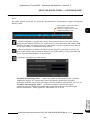
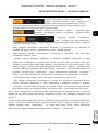
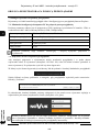
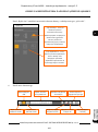
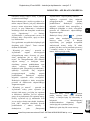
2. “Start” menu
The start menu gives access to all recorder functions. The menu is displayed after pressing the button in
the lower left corner of the screen. Menu options are available to the logged in user.
3. “Settings” menu
This menu allows to modify all main recorder settings.
RECORDER'S MENU - „START MENU”
- logs in/logs out the user into the recorder menu
- button to display the start menu
- displays the recorder shutdown window. Available options : Logout,
Reboot, Shutdown
- displays the settings menu. Description of the menu in the
chapter 3. “Settings” menu
- displays the playback menu. Description of the menu in the chapter 5.
“Playback” menu
- displays the search and archive wizard. Description of the
menu in the chapter 4. “Search and Backup” menu
- displays the image analysis menu. Description of the menu in
the chapter 6. “Intelligent Analytics” menu
- displays the name of the currently logged user

6000 series IP recorders - User’s manual - version 3.2
All rights reserved © AAT SYSTEMY BEZPIECZEŃSTWA Sp. z o.o.
10
3.1. “Camera” menu
The “Camera” menu allows to search, add to the recorder and edit the parameters of IP cameras. This
menu also allows to configure the parameters of motion detection, image analysis and programming
cruise and presets for PTZ cameras.
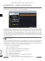
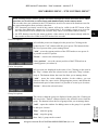
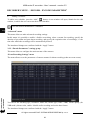
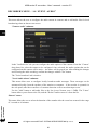
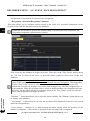
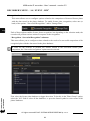
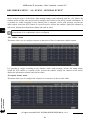
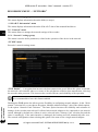
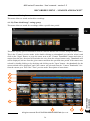
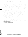
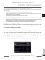
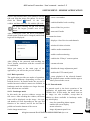
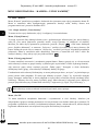
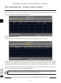
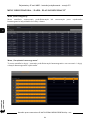
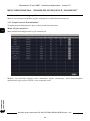
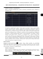
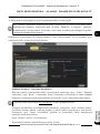
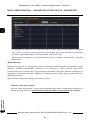
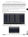
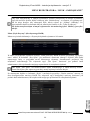
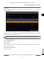
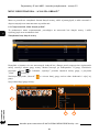
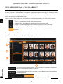
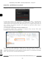
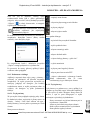
3.1.1. “Manage Camera” settings group
This menu contains options for adding, editing, configuring and removing cameras.
“Edit Camera” menu
This menu displays a list of added cameras along with basic information, such as: camera name, IP
address, port, connection status, protocol, model, firmware version (depending on the model). It is
also possible to edit connection parameters (“Edit” button ). For cameras added by “Quickly
Add” with the status “Online” it is only possible to edit the camera name, for cameras added manually
or with the status “Offline” it is possible to edit all connection parameters. This menu also allows to
update the firmware on 3000 and 6000 series cameras. To remove the camera from the list, use the
delete button.
“Edit Camera Group” menu
This menu allows to create and manage camera groups. Cameras are grouped to create mini-
sequences (cameras collected in the group are displayed sequentially in the selected channel window).
To create a group, press the “Add group” button. Then in the add window, you define the group name,
sequence time and add cameras to the group.
The mini-sequence is started using the context menu in the “live display” (menu is displayed on the
right side of the live view window). In this menu, click on the “Single Channel Sequences” bar to
display available groups. Then select in the live view window the channel, on which we want to run
the mini-sequence and double-click the name of the selected group. The mini-sequence is turned off
by right-clicking on the mini-sequence channel and selecting the “Close Dwell” option.
“IP Planning” menu
This menu allows to manage cameras and recorders in the local network. Individual and group change
of network parameters of cameras, and adding cameras to the recorder is possible. In the case of
recorders, it is possible to add/remove cameras, change the IP address, change the administrator login
data and enable the buzzer in the device location.
RECORDER'S MENU - “CAMERA - MANAGE CAMERA”
The mini-sequence can be run on any channel window, even empty.

6000 series IP recorders - User’s manual - version 3.2
All rights reserved © AAT SYSTEMY BEZPIECZEŃSTWA Sp. z o.o.
11
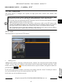
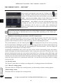
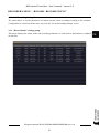
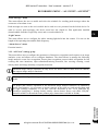
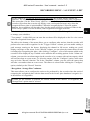
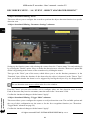
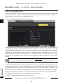
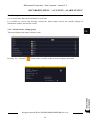
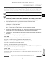
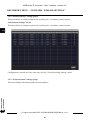
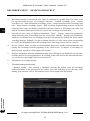
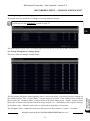
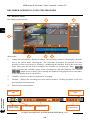
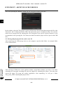
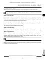
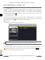
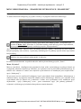
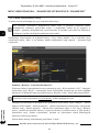
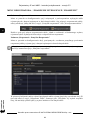
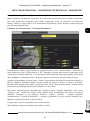
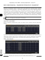
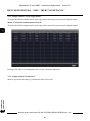
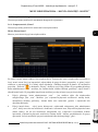
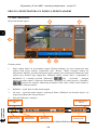
3.1.2. “Add Camera” settings group
This menu allows to add cameras and channels of other recorders to the recorder. It is also possible to
edit camera network parameters. The add window also displays information from the recorder
network card about the available bandwidth.
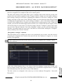
“Quickly Add” menu
After selecting this menu, the recorder automatically searches and displays available cameras.
The camera is added by selecting it in the list and click “Add” button. It is possible to select multiple
cameras and add them a few at a time, and modification of network parameters cameras.
The “Default password” button allows to set default login details for various protocols used by the
recorder to connect to cameras, which significantly speeds up and simplifies the process of adding
cameras, especially with a larger number of them.
RECORDER'S MENU - “CAMERA - ADD CAMERA”
In recorders equipped with PoE ports, configuration should be started by connecting cameras to
PoE ports. The NOVUS 3000 and 6000 series cameras will be automatically detected and added.
Cameras of other series require, before connecting, setting the IP address compatible with the
addressing range, set for the internal Ethernet port of the recorder (default 10.151.151.1). Then
enter the username and password for the camera.
Please note that adding a camera not connected to PoE ports (located on the network) takes a
logical channel for connecting the camera to the PoE port. If the camera is blocking the channel
for the camera in the PoE port, remove it from the configuration and add it after detecting the
camera connected to the PoE port.

6000 series IP recorders - User’s manual - version 3.2
All rights reserved © AAT SYSTEMY BEZPIECZEŃSTWA Sp. z o.o.
12
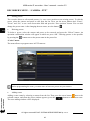
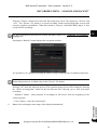
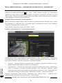
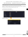
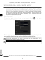
“Add Manually” menu
This menu allows you to manually create a camera in the system by providing its IP address, data port,
login data and communication protocol.
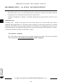
“Add Recorder” menu
This menu allows to add channels of another recorder working in the same network.
Adding a recorder is done by selecting it on the list and clicking the “Add” button. The next window
will be displayed, presenting the list of channels of the selected recorder. After selecting the desired
cameras, click OK. The window will close and the added channels will be shown in the editing
window.
The “Manual add” button allows you to manually add a recorder by entering its IP address, data port,
login data and communication protocol.
RECORDER'S MENU - “CAMERA - ADD CAMERA”
Only NOVUS 3000 or 6000 series recorders can be added.

6000 series IP recorders - User’s manual - version 3.2
All rights reserved © AAT SYSTEMY BEZPIECZEŃSTWA Sp. z o.o.
13
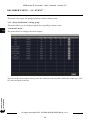
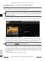
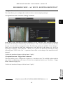
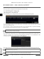
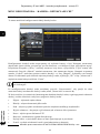
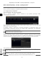
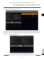
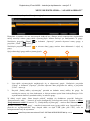
3.1.3. “Image” settings group
This menu allows to modify settings and adjust images in added cameras.
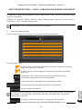
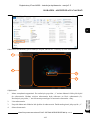
“OSD Settings” menu
This menu allows to set the channel name. It is also possible to enable / disable the channel name
display, as well as change the format and enable / disable the date and time display. To change the
position of the OSD on the image, click and hold the left mouse button on the red border, move the
OSD to the desired location.
In this menu it is also possible to add a watermark (in text form), which will be displayed during
playback of recordings from a given channel only, if the recording will not be modified in any way.
To save the settings, press the “Apply” button.
“Image Settings” menu
In this menu, we can set image parameters such as brightness, contrast, saturation, hue and other,
depending on the camera. Use the “Default” button to set default image values.
“Mask Settings” menu
This menu allows to set privacy zones. To set the zone, press the “Draw” button and holding the left
mouse button pressed, select the appropriate area on the image. Then enable the mask by selecting
“On” from the “Mask” drop-down list. To save the settings, press the “Apply” button.
“Fisheye Settings” menu
This menu contains image settings for fisheye cameras. You can select the display mode and specify
the camera installation location.
RECORDER'S MENU - “CAMERA - IMAGE”
The range of available settings and adjustments may vary depending on the camera type /
model / manufacturer.
It is possible to set up to four privacy zones (masks).

6000 series IP recorders - User’s manual - version 3.2
All rights reserved © AAT SYSTEMY BEZPIECZEŃSTWA Sp. z o.o.
14
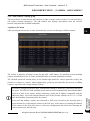
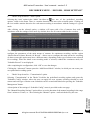
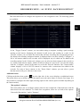
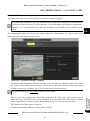
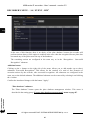
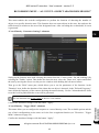
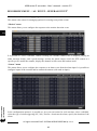
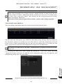
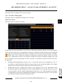
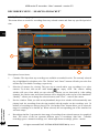
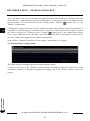
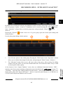
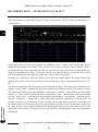
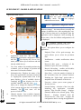
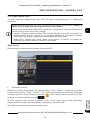
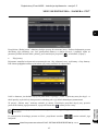
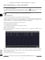
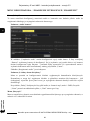
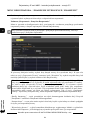
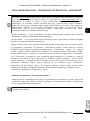
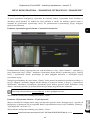
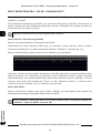
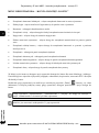
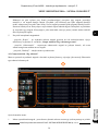
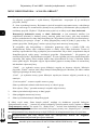
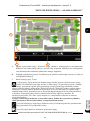
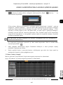
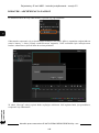
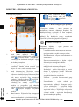
3.1.4. “Motion Settings” settings group
This menu allows you to configure the motion detection function.
Configuring motion detection starts by selecting a camera from the list. Then set the zone: select the
appropriate area on the image, holding the left mouse button pressed. The “All” button can be used to
select the entire image, and the “Clear” button can be used to remove the entire selection. The
“Reverse” button replaces selected and unselected areas. Then, using the “Sensitivity” slider, set the
detection sensitivity level, and select the duration of the alarm from the “Duration” list. After making
these settings, enable motion detection by selecting “On” from the “Motion” list and save the settings
with the “Apply” button.
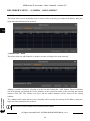
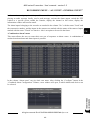
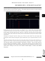
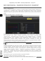
After configuring motion detection, press the “Processing Mode” button to go to the “Alarm Handling
Settings” window for setting the response to the motion detection event (“Motion” menu on page 44).
In the window it is possible to set the motion detection schedule, the rules for recording the detection
event, as well as to set the response to the occurrence of motion detection:
• Snapshot - performing saving snapshot
• Audio - starts playing the audio file
• Push - enables sending push messages to the user's mobile device
• Alarm-out - activation of alarm outputs in camera or recorder
• Preset - selects the preset for PTZ cameras
• Buzzer - enabling the sound signaller
• Pop-up Video - displays the image in a window appearing on the screen
• E-mail - sends an email notification
RECORDER'S MENU - “CAMERA - MOTION SETTINGS”
For cameras other than Novus 3000 or 6000 series, motion detection or some of its options may
not be available.

6000 series IP recorders - User’s manual - version 3.2
All rights reserved © AAT SYSTEMY BEZPIECZEŃSTWA Sp. z o.o.
15
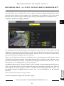
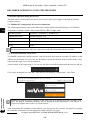
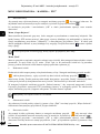
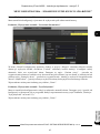
3.1.5. “PTZ” settings group
This menu allows to configure PTZ options for high speed dome cameras and cameras with
motorzoom lens.
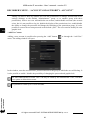
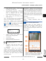
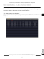
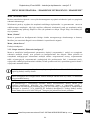
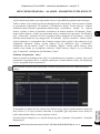
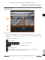
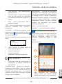
“Preset” menu
The menu allows to set presets on PTZ cameras.
• Adding presets
Adding presets starts by selecting a camera from the “Camera” list. Using the arrow buttons and the
“Zoom”, “Focus” and “Iris” buttons set the desired field of observation, and then press the “Add”
button or the arrow button next to the selected camera (a preset window will appear in which we
press the button ).
In the newly opened preset window, select the preset number from the “Preset” list that you want to
save (you can also give it your own name) and save with “OK”.
In the same way you can add more presets.
RECORDER'S MENU - “CAMERA - PTZ”
When creating presets, cruises, groups and tracks through the menus described above, these
functions are saved in the recorder menu and simultaneously in the camera menu.
The recorder does not synchronize the PTZ functions saved in its menu with functions saved in
the camera through its menu (website), therefore:
• PTZ functions previously saved in the camera, will not be visible in the PTZ menu of the
recorder after adding the camera to it. This means that if, for example, presets were saved in
the camera before it were added to the recorder, they can be overwritten without warning.
• the PTZ function saved by the menu (website) of the camera, in the camera already added to
the recorder will not be visible in the PTZ menu of the recorder.

6000 series IP recorders - User’s manual - version 3.2
All rights reserved © AAT SYSTEMY BEZPIECZEŃSTWA Sp. z o.o.
16
• Editing presets
The recorder allows to edit created presets (i.e. save a new position on an existing preset). To edit the
preset, select the camera and preset to edit from the list. Next, use the arrow buttons and “Zoom”,
“Focus” and “Iris” to set a new observation field and press the “Save position” button. You can also
change the preset name. After changing the new name, save the button
• Deleting presets
To delete a preset, select the camera and preset to be removed and press the “Delete” button. An
operation confirmation window will appear in which we press “OK”. Deleting presets is also possible
by pressing the button next to the preset name in the preset list.
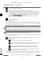
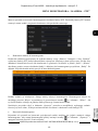
“Cruise” menu
The menu allows to program routes in PTZ cameras.
• Adding routes
Adding a route starts by selecting a camera from the list. Then press the arrow button next to the
selected camera, and when the preset window appears, press the button to add a new route.
The route adding window will be displayed:
RECORDER'S MENU - “CAMERA - PTZ”
Before programming the route, you must store at least two presets on your camera.

6000 series IP recorders - User’s manual - version 3.2
All rights reserved © AAT SYSTEMY BEZPIECZEŃSTWA Sp. z o.o.
17
The “Add preset” button is used to add additional presets to the created route. When adding a preset, its
parameters are defined, i.e. the time camera stays on the given preset and movement speed (these
parameters can also be changed later, by pressing the button in the “Edit” column).
• Editing a route
The recorder allows you to edit created routes. To edit the route, select the camera from the list.
Editable route options will be displayed under the preview window.
If more than one route is added to the camera, the “Cruise” list is used to select the route to be edited -
the table below will display the list of presets included in it with their current parameters.
In the “Cruise name” position, we can change route name. Pressing the edit button next on the preset,
allows to change its parameters, and the delete button removes the preset from the route.
After selecting any preset in the list, you can change the order with the arrow buttons.
RECORDER'S MENU - “CAMERA - PTZ”
This action deletes the preset as part of the route, but does not delete it from the list of presets
saved in the camera.

6000 series IP recorders - User’s manual - version 3.2
All rights reserved © AAT SYSTEMY BEZPIECZEŃSTWA Sp. z o.o.
18
• Deleting a route
To delete a route, select the camera and then press the button to open the route list window. After
hovering over the name of the route to delete, the delete button will be displayed.
After pressing the button and confirming with “OK” in the confirmation window, the route will be
deleted.
“Cruise Group” menu
The menu allows you to create groups of routes which are then run in a preset order. One cruise group
can be created for each PTZ camera, consisting of up to eight routes. The group is started with the
"Play" button, and stopped with the "Stop" button. The table below the preview window, shows the
routes that make up the group. The delete button removes the selected route from the group.
“Trace” menu
This menu allows you to save (record) your own trace (path), which the camera will then faithfully
repeat. This option differs from the "Cruise” menu in that no presets are needed to create a track: when
creating a path, the camera saves the commands given to it.
• Adding path
Adding a path starts by selecting a camera from the list. Then press the arrow button next to the
selected camera, and when path window appears, press the button to add a new path. You can
also add the path using the "Add" button. A window will open, in which the default name of the new
path will be displayed. The name can be freely changed.
Next, press the "Start Record" button to start recording the path. By using the PTZ control buttons
move the camera in the required manner. After finishing the recording, press the button "Stop Record ".
The path will be saved.
• Playing a path
To play a path, select its number from the "Trace" list and press the "Run trace" button. We stop
playing with the “Stop Trace” button.
• Deleting a path
To delete a path, select the camera and then press the button to open the paths list window. After
hovering over the name of the path to delete, the delete button will be displayed.
After pressing the button and confirming with “OK” in the confirmation window, the path will be
deleted.
The path can also be deleted with the "Delete" button, after selecting its number from the list of paths.
RECORDER'S MENU - “CAMERA - PTZ”
Before setting the cruise group, you must store at least two routes on your camera.
The maximum recording time for a path is 180 seconds.

6000 series IP recorders - User’s manual - version 3.2
All rights reserved © AAT SYSTEMY BEZPIECZEŃSTWA Sp. z o.o.
19
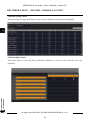
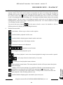
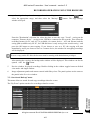
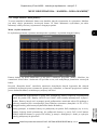
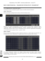
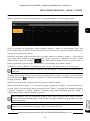
“Task” menu
This menu allows you to schedule PTZ operation. For each PTZ camera, you can create a set of tasks
and assign a time slot to each of them.
• Adding a task to the schedule
Adding a task begins with selecting a camera from the "Camera" list. Then, from the "Function" list,
select the PTZ function that the camera will perform. We can choose a preset, route, path and
additionally random scanning or boundary scanning. Finally, in the "Start Time" and "End Time"
fields, define the time limits for the function operation and add to the schedule with the "Add" button.
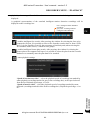
After adding all tasks, go to the schedule window:
The added tasks are inactive, so enable the schedule. The schedule is turned on by pressing the
"Enable" button displayed after pressing the arrow in the "Enable" column. From now on, the
camera waits for the start time of the first set task.
Pressing the edit button in the "Operation" column allows you to modify the selected task. A new
window will open where you can change the start and end times and the PTZ function.
• Deleting the schedule
The recorder does not allow you to delete individual tasks, it is only possible to delete the entire
schedule. To delete the schedule, press the arrow in the "Operation" column and then press the
"Delete All" button.
RECORDER'S MENU - “CAMERA - PTZ”

6000 series IP recorders - User’s manual - version 3.2
All rights reserved © AAT SYSTEMY BEZPIECZEŃSTWA Sp. z o.o.
20
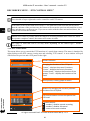
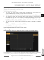
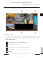
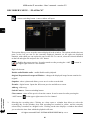
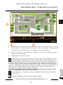
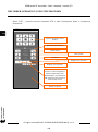
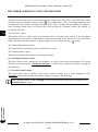
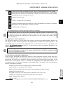
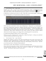
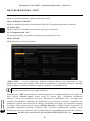
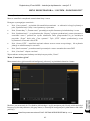
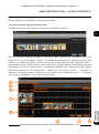
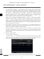
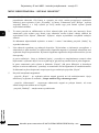
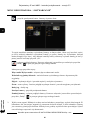
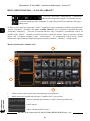
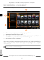
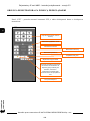
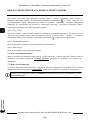
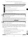
3.1.6. PTZ control menu
This menu allows you to control the PTZ functions of a speed dome camera. The menu is launched by
right-clicking on the PTZ camera viewing area and selecting "PTZ control". A new window will open
with full screen preview and a PTZ panel on the right:
RECORDER'S MENU - “PTZ CONTROL MENU”
One schedule of up to eight tasks can be created for each PTZ camera.
If the times of the created tasks will overlap, i.e. the start time of the next task will be earlier
than the end time of the previous one, the camera will execute the previous task until the set end
time and then move to the next one. If you set two tasks with the same start and end times, the
camera will execute the first task.
Manual PTZ control is possible while the camera is executing schedule tasks. However, when
the operator completes control, the camera will resume its tasks.
The range of tasks that can be set may differ depending on the camera type / model /
manufacturer.
Camera selecon
Changing the funcons of the PTZ panel:
"Preset" - displays the preset’s funcons,
"Cruise" - displays the cruise’s funcons,
"Cruise Group" - displays the funcons of the
groups, "Trace" - displays the funcons of the
tracks
List of presets, cruises, groups or tracks
PTZ control buons and set the speed of the
PTZ head.
Buons for managing the currently selected
funcon of the PTZ panel.
Funcon buons:
- enables / disables manual recording
- enables / disables 3D control
- return to the main window
Strona się ładuje...
Strona się ładuje...
Strona się ładuje...
Strona się ładuje...
Strona się ładuje...
Strona się ładuje...
Strona się ładuje...
Strona się ładuje...
Strona się ładuje...
Strona się ładuje...
Strona się ładuje...
Strona się ładuje...
Strona się ładuje...
Strona się ładuje...
Strona się ładuje...
Strona się ładuje...
Strona się ładuje...
Strona się ładuje...
Strona się ładuje...
Strona się ładuje...
Strona się ładuje...
Strona się ładuje...
Strona się ładuje...
Strona się ładuje...
Strona się ładuje...
Strona się ładuje...
Strona się ładuje...
Strona się ładuje...
Strona się ładuje...
Strona się ładuje...
Strona się ładuje...
Strona się ładuje...
Strona się ładuje...
Strona się ładuje...
Strona się ładuje...
Strona się ładuje...
Strona się ładuje...
Strona się ładuje...
Strona się ładuje...
Strona się ładuje...
Strona się ładuje...
Strona się ładuje...
Strona się ładuje...
Strona się ładuje...
Strona się ładuje...
Strona się ładuje...
Strona się ładuje...
Strona się ładuje...
Strona się ładuje...
Strona się ładuje...
Strona się ładuje...
Strona się ładuje...
Strona się ładuje...
Strona się ładuje...
Strona się ładuje...
Strona się ładuje...
Strona się ładuje...
Strona się ładuje...
Strona się ładuje...
Strona się ładuje...
Strona się ładuje...
Strona się ładuje...
Strona się ładuje...
Strona się ładuje...
Strona się ładuje...
Strona się ładuje...
Strona się ładuje...
Strona się ładuje...
Strona się ładuje...
Strona się ładuje...
Strona się ładuje...
Strona się ładuje...
Strona się ładuje...
Strona się ładuje...
Strona się ładuje...
Strona się ładuje...
Strona się ładuje...
Strona się ładuje...
Strona się ładuje...
Strona się ładuje...
Strona się ładuje...
Strona się ładuje...
Strona się ładuje...
Strona się ładuje...
Strona się ładuje...
Strona się ładuje...
Strona się ładuje...
Strona się ładuje...
Strona się ładuje...
Strona się ładuje...
Strona się ładuje...
Strona się ładuje...
Strona się ładuje...
Strona się ładuje...
Strona się ładuje...
Strona się ładuje...
Strona się ładuje...
Strona się ładuje...
Strona się ładuje...
Strona się ładuje...
Strona się ładuje...
Strona się ładuje...
Strona się ładuje...
Strona się ładuje...
Strona się ładuje...
Strona się ładuje...
Strona się ładuje...
Strona się ładuje...
Strona się ładuje...
Strona się ładuje...
Strona się ładuje...
Strona się ładuje...
Strona się ładuje...
Strona się ładuje...
Strona się ładuje...
Strona się ładuje...
Strona się ładuje...
Strona się ładuje...
Strona się ładuje...
Strona się ładuje...
Strona się ładuje...
Strona się ładuje...
Strona się ładuje...
Strona się ładuje...
Strona się ładuje...
Strona się ładuje...
Strona się ładuje...
Strona się ładuje...
Strona się ładuje...
Strona się ładuje...
Strona się ładuje...
Strona się ładuje...
Strona się ładuje...
Strona się ładuje...
Strona się ładuje...
Strona się ładuje...
Strona się ładuje...
Strona się ładuje...
Strona się ładuje...
Strona się ładuje...
Strona się ładuje...
Strona się ładuje...
Strona się ładuje...
Strona się ładuje...
Strona się ładuje...
Strona się ładuje...
Strona się ładuje...
Strona się ładuje...
Strona się ładuje...
Strona się ładuje...
Strona się ładuje...
Strona się ładuje...
Strona się ładuje...
Strona się ładuje...
Strona się ładuje...
Strona się ładuje...
Strona się ładuje...
Strona się ładuje...
Strona się ładuje...
Strona się ładuje...
Strona się ładuje...
Strona się ładuje...
Strona się ładuje...
Strona się ładuje...
Strona się ładuje...
Strona się ładuje...
Strona się ładuje...
Strona się ładuje...
Strona się ładuje...
Strona się ładuje...
Strona się ładuje...
Strona się ładuje...
Strona się ładuje...
Strona się ładuje...
Strona się ładuje...
Strona się ładuje...
Strona się ładuje...
Strona się ładuje...
Strona się ładuje...
Strona się ładuje...
Strona się ładuje...
Strona się ładuje...
Strona się ładuje...
Strona się ładuje...
Strona się ładuje...
Strona się ładuje...
Strona się ładuje...
Strona się ładuje...
Strona się ładuje...
Strona się ładuje...
Strona się ładuje...
Strona się ładuje...
Strona się ładuje...
Strona się ładuje...
Strona się ładuje...
Strona się ładuje...
Strona się ładuje...
Strona się ładuje...
Strona się ładuje...
Strona się ładuje...
Strona się ładuje...
Strona się ładuje...
Strona się ładuje...
Strona się ładuje...
Strona się ładuje...
Strona się ładuje...
Strona się ładuje...
Strona się ładuje...
Strona się ładuje...
Strona się ładuje...
Strona się ładuje...
Strona się ładuje...
Strona się ładuje...
Strona się ładuje...
Strona się ładuje...
Strona się ładuje...
Strona się ładuje...
Strona się ładuje...
Strona się ładuje...
Strona się ładuje...
Strona się ładuje...
Strona się ładuje...
Strona się ładuje...
Strona się ładuje...
Strona się ładuje...
Strona się ładuje...
Strona się ładuje...
Strona się ładuje...
Strona się ładuje...
Strona się ładuje...
Strona się ładuje...
Strona się ładuje...
Strona się ładuje...
Strona się ładuje...
Strona się ładuje...
Strona się ładuje...
Strona się ładuje...
Strona się ładuje...
Strona się ładuje...
Strona się ładuje...
-
 1
1
-
 2
2
-
 3
3
-
 4
4
-
 5
5
-
 6
6
-
 7
7
-
 8
8
-
 9
9
-
 10
10
-
 11
11
-
 12
12
-
 13
13
-
 14
14
-
 15
15
-
 16
16
-
 17
17
-
 18
18
-
 19
19
-
 20
20
-
 21
21
-
 22
22
-
 23
23
-
 24
24
-
 25
25
-
 26
26
-
 27
27
-
 28
28
-
 29
29
-
 30
30
-
 31
31
-
 32
32
-
 33
33
-
 34
34
-
 35
35
-
 36
36
-
 37
37
-
 38
38
-
 39
39
-
 40
40
-
 41
41
-
 42
42
-
 43
43
-
 44
44
-
 45
45
-
 46
46
-
 47
47
-
 48
48
-
 49
49
-
 50
50
-
 51
51
-
 52
52
-
 53
53
-
 54
54
-
 55
55
-
 56
56
-
 57
57
-
 58
58
-
 59
59
-
 60
60
-
 61
61
-
 62
62
-
 63
63
-
 64
64
-
 65
65
-
 66
66
-
 67
67
-
 68
68
-
 69
69
-
 70
70
-
 71
71
-
 72
72
-
 73
73
-
 74
74
-
 75
75
-
 76
76
-
 77
77
-
 78
78
-
 79
79
-
 80
80
-
 81
81
-
 82
82
-
 83
83
-
 84
84
-
 85
85
-
 86
86
-
 87
87
-
 88
88
-
 89
89
-
 90
90
-
 91
91
-
 92
92
-
 93
93
-
 94
94
-
 95
95
-
 96
96
-
 97
97
-
 98
98
-
 99
99
-
 100
100
-
 101
101
-
 102
102
-
 103
103
-
 104
104
-
 105
105
-
 106
106
-
 107
107
-
 108
108
-
 109
109
-
 110
110
-
 111
111
-
 112
112
-
 113
113
-
 114
114
-
 115
115
-
 116
116
-
 117
117
-
 118
118
-
 119
119
-
 120
120
-
 121
121
-
 122
122
-
 123
123
-
 124
124
-
 125
125
-
 126
126
-
 127
127
-
 128
128
-
 129
129
-
 130
130
-
 131
131
-
 132
132
-
 133
133
-
 134
134
-
 135
135
-
 136
136
-
 137
137
-
 138
138
-
 139
139
-
 140
140
-
 141
141
-
 142
142
-
 143
143
-
 144
144
-
 145
145
-
 146
146
-
 147
147
-
 148
148
-
 149
149
-
 150
150
-
 151
151
-
 152
152
-
 153
153
-
 154
154
-
 155
155
-
 156
156
-
 157
157
-
 158
158
-
 159
159
-
 160
160
-
 161
161
-
 162
162
-
 163
163
-
 164
164
-
 165
165
-
 166
166
-
 167
167
-
 168
168
-
 169
169
-
 170
170
-
 171
171
-
 172
172
-
 173
173
-
 174
174
-
 175
175
-
 176
176
-
 177
177
-
 178
178
-
 179
179
-
 180
180
-
 181
181
-
 182
182
-
 183
183
-
 184
184
-
 185
185
-
 186
186
-
 187
187
-
 188
188
-
 189
189
-
 190
190
-
 191
191
-
 192
192
-
 193
193
-
 194
194
-
 195
195
-
 196
196
-
 197
197
-
 198
198
-
 199
199
-
 200
200
-
 201
201
-
 202
202
-
 203
203
-
 204
204
-
 205
205
-
 206
206
-
 207
207
-
 208
208
-
 209
209
-
 210
210
-
 211
211
-
 212
212
-
 213
213
-
 214
214
-
 215
215
-
 216
216
-
 217
217
-
 218
218
-
 219
219
-
 220
220
-
 221
221
-
 222
222
-
 223
223
-
 224
224
-
 225
225
-
 226
226
-
 227
227
-
 228
228
-
 229
229
-
 230
230
-
 231
231
-
 232
232
-
 233
233
-
 234
234
-
 235
235
-
 236
236
-
 237
237
-
 238
238
-
 239
239
-
 240
240
-
 241
241
-
 242
242
-
 243
243
-
 244
244
-
 245
245
-
 246
246
-
 247
247
-
 248
248
-
 249
249
-
 250
250
-
 251
251
-
 252
252
-
 253
253
-
 254
254
-
 255
255
-
 256
256
-
 257
257
-
 258
258
-
 259
259
-
 260
260


w innych językach
- English: Novus NVR-6204P4-H1 User manual
Powiązane artykuły
-
Novus NVR-6332-H2/F Instrukcja obsługi
-
-
-
-
-
Novus NVIP-5VE-6201-II Instrukcja obsługi
-
Novus NVIP-4H-4231/WLAD Instrukcja obsługi
-
Novus NVIP-5H-6502M/F Instrukcja obsługi
-
-
