flowair Cube R8 Instrukcja obsługi
- Kategoria
- Klimatyzatory typu split
- Typ
- Instrukcja obsługi
Niniejsza instrukcja jest również odpowiednia dla

www.flowair.com | 1
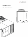
Rooftop Cube
TECHNICAL DOCUMENTATION
USER’S AND INSTALLATION MANUAL
DTR Cube v2.6 EN

2 |www.flowair.com
v2.6 MT-DTR-CUBE/TOTAL-EN-V2 64946
11.2022r

www.flowair.com | 3
Thank you for purchasing Cube unit.
This manual was published by FLOWAIR Sp. z. o. o. (formerly FLOWAIR Głogowski and Brzeziński Sp. J.). User’s and installation
manual is a set of recommendations and tips designed to show procedures, methods and remarks for proper installation, launch
and operation of the unit.
The manufacturer reserves the right to correct and change the user’s manual anytime without notice, so as changes in
the devices not influencing its operation.
The manual is an integral part of the device and must be delivered with it to the customer. Before installation, launch and operation
of Cube device, the customer should read thoroughly this manual, especially with security section to eliminate risk of harm to the
health or damage to material property. All guidelines mentioned in the manual should be applied without omitting any point.
Failure to adhere to the following points may result in life-threating due to improper transport and installation and can lead to
damages to the unit or its improper operation. The manufacturer shall not be liable for deficiencies during installation and unit
improper operation due to failure to comply with this manual. Meanwhile, the producer’s warranty will not be applied in case of
gross negligence or not complying with this manual.
You should consult the service or manufacturer if this manual contains incomprehensible or ambiguous descriptions.
It should be ensured that all users of unit are complied with this manual before launching it. In case of unit’s transfer to
another user, this manual must also be transferred.
All activities during connecting to electrical installation must be conducted by qualified staff, having necessary
attestations and certificates to work with voltage devices according to the laws of the country.
This manual is only intended to use for persons using or installing the Cube devices. Its content is legally protected and must not
be copied, translated or processed (including electronic media) in total or partially without the manufacturer’s written declaration
of consent.
FLOWAIR Sp. z. o. o.
(formerly FLOWAIR Głogowski i Brzeziński Sp.J.)
Office:
ul. Chwaszczyńska 135, 81-571 Gdynia
tel. +48 (58) 627 57 41, fax +48 (58) 627 57 21

4 |www.flowair.com
TABLE OF CONTENTS
TECHNICAL DOCUMENTATION: EN
1. IMPORTANT INFORMATION ...................................................................................................................................................................................... 6
2. REGULATIONS................................................................................................................................................................................................................ 9
2.1. Regulation (EC) No 842/2006 of the European Parliament and the Council ........................................................................................ 9
3. GENERAL INFORMATION .......................................................................................................................................................................................... 10
3.1. Cube application ............................................................................................................................................................................................. 10
3.2. Device configuration ..................................................................................................................................................................................... 10
3.3. General characteristics construction Cube 20 ....................................................................................................................................... 12
3.4. General characteristics construction Cube 40 ....................................................................................................................................... 12
3.5. General characteristics construction Cube 50 – 100 ............................................................................................................................ 13
3.6. General characteristics construction Cube 120/160 ............................................................................................................................ 14
3.7. General characteristics construction Cube R8 ....................................................................................................................................... 15
3.8. General characteristics construction supply module .......................................................................................................................... 15
4. TECHNICAL DATA ....................................................................................................................................................................................................... 16
4.1. Technical parameters – cooling devices for duct installation (Cube 20 -160) ................................................................................... 16
4.2. Technical parameters – ventilation devices for duct installation - Cube R8 ...................................................................................... 19
4.3. Technical parameters – cooling devices for ductless instalation – Cube 20 NWS; Cube 40 NWL ............................................... 20
4.4. Technical parameters – ventilation devices for ductless installation - Cube R8 NWS .................................................................... 22
4.5. Air flow diagram - ventilation part Cube 20 - 100 ...................................................................................................................................... 23
4.6. Air flow diagram - ventilation part Cube 120/160 ...................................................................................................................................... 24
4.7. Air flow diagram - ventilation part Cube R8 ................................................................................................................................................. 25
4.8. Cube 20 charts – cooling module .................................................................................................................................................................... 26
4.9. Cube 20 HP charts – heat pump module ...................................................................................................................................................... 27
4.10. Cube 40 charts – cooling module .............................................................................................................................................................. 28
4.11. Cube 40 HP charts – heat pump module ................................................................................................................................................ 29
4.12. Cube 50-100 charts – cooling module ..................................................................................................................................................... 30
4.13. Cube 50-100 HP charts – heat pump module ....................................................................................................................................... 31
4.14. Cube 120/160 charts – cooling module ................................................................................................................................................... 32
4.15. Cube 120/160 HP charts – heat pump module ..................................................................................................................................... 33
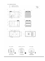
4.16. Service distances ............................................................................................................................................................................................. 34
4.17. Dimensions Cube 20 ...................................................................................................................................................................................... 36
4.18. Dimensions Cube 20 NWS D ....................................................................................................................................................................... 37
4.19. Dimensions Cube 20 NWS V ........................................................................................................................................................................ 38
4.20. Dimensions Cube 40 ...................................................................................................................................................................................... 39
4.21. Dimensions Cube 40 NWL D........................................................................................................................................................................ 40
4.22. Dimensions Cube 40 NWL V ........................................................................................................................................................................ 41
4.23. Dimensions Cube 50/60 ............................................................................................................................................................................... 42
4.24. Dimensions Cube 80/100 ............................................................................................................................................................................. 43
4.25. Dimensions Cube 80/100 L ......................................................................................................................................................................... 44
4.26. Dimensions Cube 120/160 B ....................................................................................................................................................................... 45
4.27. Dimensions 120/160 R .................................................................................................................................................................................. 46
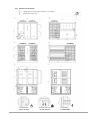
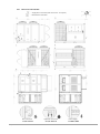
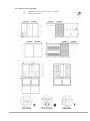
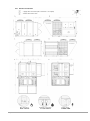
4.28. Dimensions Cube R8 ...................................................................................................................................................................................... 47
4.29. Dimensions Cube R8 NWS D ....................................................................................................................................................................... 48
4.30. Dimensions Cube R8 NWS V ........................................................................................................................................................................ 49
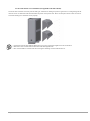
5. TRANSPORT .................................................................................................................................................................................................................. 50
5.1. Horizontal transport ............................................................................................................................................................................................ 50
5.2. Transport dimensions Cube 20 ........................................................................................................................................................................ 50
5.3. Transport dimensions Cube 40 ........................................................................................................................................................................ 51
5.4. Transport dimensions Cube 50/60 .................................................................................................................................................................. 51
5.5. Transport dimensions Cube 80/100 ............................................................................................................................................................... 51
5.6. Transport dimensions Cube 80/100 L ........................................................................................................................................................... 52
5.7. Transport dimensions Cube 120/160 B ......................................................................................................................................................... 52
5.8. Transport dimensions Cube 120/160 R ......................................................................................................................................................... 52
5.9. Transport dimensions Cube R8 ........................................................................................................................................................................ 53
5.10. Transport dimensions NWS module (Cube 20/R8 NWS) .................................................................................................................... 53
5.11. Transport dimensions NWL module (Cube 40 NWL) ........................................................................................................................... 53
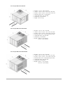
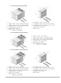
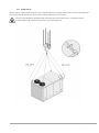
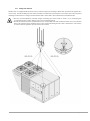
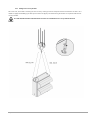
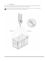
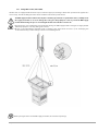
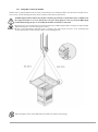
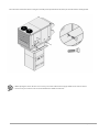
5.12. Lifting information ......................................................................................................................................................................................... 54
5.13. Lifting Cube 20 ................................................................................................................................................................................................ 55
5.14. Lifting Cube 40 ................................................................................................................................................................................................ 56
5.15. Lifting Cube 50/60 .......................................................................................................................................................................................... 57
5.16. Lifting Cube 80/100 ........................................................................................................................................................................................ 58
5.17. Lifting Cube 120/160 ..................................................................................................................................................................................... 59
5.18. Lifting heat recovery module ...................................................................................................................................................................... 60
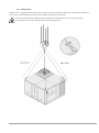
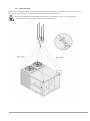
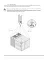
5.19. Lifting Cube R8 ................................................................................................................................................................................................ 61
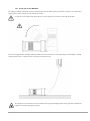
5.20. Rotating the module NWS/NWL ................................................................................................................................................................ 62

www.flowair.com | 5
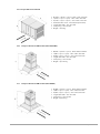
5.21. Lifting NWS module (Cube 20/R8) ............................................................................................................................................................. 64
5.22. Lifting NWL module(Cube 40 NWL) .......................................................................................................................................................... 65
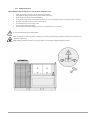
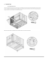
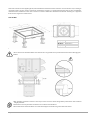
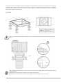
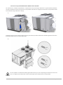
6. FOUNDATION .............................................................................................................................................................................................................. 66
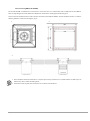
6.1. Foundation Cube unit ......................................................................................................................................................................................... 66
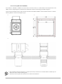
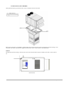
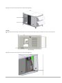
6.2. Roof crosing NWS (Cube 20/R8 NWS) ............................................................................................................................................................ 74
6.3. NWS instalation (Cube 20/R8 NWS) ................................................................................................................................................................ 75
6.4. Roof crossing NWL (Cube 40 NWL) ................................................................................................................................................................. 78
6.5. NWL installation (Cube 40 NWL) ...................................................................................................................................................................... 79
6.6. Ventilation channels connection ..................................................................................................................................................................... 81
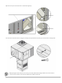
6.7. Inlet and exhaust covers installation (not applicable to the Cube 40 unit) ........................................................................................ 82
6.8. Heat recovery unit installation Cube 80/100 L i Cube 120/160 R .......................................................................................................... 83
7. INSTALLATION ............................................................................................................................................................................................................. 85
7.1. Hydraulic connection - units for duct installation ...................................................................................................................................... 85
7.2. Hydraulic hub chart for water heater in the rooftop unit ........................................................................................................................ 86
7.3. Hydraulic connection – units dor ductless installation ............................................................................................................................. 87
7.4. Hydraulic hub chart for water heater in the NW module ......................................................................................................................... 88
7.5. Condensation drain ............................................................................................................................................................................................. 89
7.6. Electric connection............................................................................................................................................................................................... 91
7.7. Installation flow chart ........................................................................................................................................................................................ 100
8. START-UP AND EXPLOITATION ............................................................................................................................................................................ 102
8.1. Gas heater ............................................................................................................................................................................................................. 102
8.2. Electric heater ...................................................................................................................................................................................................... 103
8.3. Water heat exchanger ....................................................................................................................................................................................... 103
8.4. Water cooler ......................................................................................................................................................................................................... 103
8.5. Rotational exchanger ........................................................................................................................................................................................ 103
8.6. Fans ......................................................................................................................................................................................................................... 103
8.7. Dampers ................................................................................................................................................................................................................ 104
8.8. Automation control systems ........................................................................................................................................................................... 104
8.9. Filter replacment................................................................................................................................................................................................. 104
9. RESPONSIBILITY TABLE ........................................................................................................................................................................................... 108
10. SERVICE AND WARRANTY ................................................................................................................................................................................ 109

6 |www.flowair.com
TECHNICAL DOCUMENTATION: EN
1. IMPORTANT INFORMATION
This manual contains important information about preventing possible accidents and damage to Cube units during operation.
Special care should be taken during all actions with the unit and obey to this manual and all technical data. FLOWAIR shall not be
responsible for any omissions and damages caused by them.
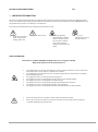
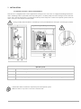
In the manual you will find warnings and important tip marked as below:
Threat of loss of life or
health or permanent
damage to the unit.
Risk of electric shock.
Warnings regarding
unauthorized use of Cube
devices. Unsafe practices,
the occurrence of which
may result in property
damage or minor personal
injury.
Advice and
information on how to
use Cube devices.
SAFETY INFORMATION:
Cube units are compiled with PED 97/23/UE directive (does not apply to Cube R8)
Obey safety instructions under all circumstances!
• It is prohibited to use Cube units for industrial vacuum caused by renovations or other construction
works when dust, harsh or explosive compounds are emitted.
• It is prohibited to use Cube units for rooms’ ventilation system where harsh chemicals are emitted
due to buildings purposes.
• The appliance presents a risk of injury from rotating parts.
• The appliance presents a risk of injury from sharp edges and considerable weight.
• The appliance presents a risk of injury from compressed gas.
• The appliance presents a risk of injury from high and low temperature elements.
• The appliance presents a risk of injury from burns to the refrigerant.
• The appliance presents a risk of injury from burns from high-temperature exhaust fumes.
• Prior to start operations it is essential to switch off the unit with main switch.
• Prior to open casing it is essential to assure that electricity is disconnected and secured against
accidental switching on by other persons.

www.flowair.com | 7
• Cube units must not be used by children or adults with reduced mobility, or limited mental abilities.
• Cube units must not be used by non-trained users or who are not familiar with this manual.
• Cube unit must be used in accordance with its intended use.
• All installation or service works must be done by qualified staff with proper attestations for electricity
and controlled substances (cooling factors).
• Staff should wear suitable protective equipment (helmet, glasses, gloves, etc.).
• During cooling unit operation, some of its parts heat up over 60°C. Precautions shall be taken. Even after
switching off the unit, high temperature may persist which can lead to skin burns.
• Do not touch water exchanger radiators, condenser or vaporizer.
• Do not touch electric heaters with skin under any circumstances.
• Pressure monitoring, filling or emptying cooling systems must be done with existing installation and
proper equipment.
• Installation must be drained from any refrigerant before any dismantling or unsoldering to avoid
explosion risk due to oil and refrigerant splashes.
• Tampering in cooling system by abusing cables or other elements is unacceptable as it may lead to
cooling system decompression and refrigerant leak to atmosphere. The direct contact with refrigerant
may lead to hands or mucous membranes frostbites.
• In order to comply with CE regulations, only original spare parts accepted by the manufacturer can be
used..
• Cube’s cooling system is equipped with safety system protecting against pressure increase, however
containment loss can happen due to safety valve trigger or system unsealing. In such case please leave
the place immediately and call the service. .
• After service works make sure that doors are closed..
• Before unit is launched make sure that all fans and moving parts won’t be interfered by any external
factors.
REFIGERANT:
Cube’s cooling system is filled with R410A – R32/125 (50/50%) refrigerants. It is a HFC group refrigerant not containing chlorine
atoms, therefore it’s ecological and was authorized to use with no limitation.
R410A refrigerant is non-explosive and non-toxic (PED 2nd group), however when contacted with fire, some toxic or corrosive
vapors may appear because of thermal decomposition. Inhaling large amount of this factor may result in narcotic state, oedema,
arrhythmias and in extreme cases – heart attacks and sensitization to adrenaline.
R410A refrigerant, if in contact with fire can create toxic and corrosive (high moisture) hydrogen fluorine
vapors.
R410A refrigerant is heavier than air (gas density 0,44kg/m3) therefore in case of leakage it can accumulate
in hollows, displacing oxygen – risk of suffocation.
In case of first aid need due to injuries caused by:
• Do not administer medication to a person in distress.
• Move to fresh air, administer oxygen and apply artificial respiration if necessary. Leave the victim in safe place. Call the
ambulance.
• Do not administer adrenaline or any similar substances.
In case of a frostbite sprinkle with water for at least 15 minutes. Put a sterile dressing and ask for medical help.
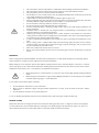
RESIDUAL HAZARD
Despite the Cube unit was designed and tested to be fully safe during operation, there is a slight risk connected to improper
use. The residual risk is connected with improper servicing by a user. By obeying the rules mentioned in points 1.10. and 1.11. a
risk is limited to the lowest level, where there will be no risk of life, health or natural environment.

8 |www.flowair.com
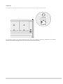
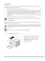
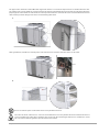
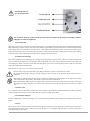
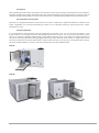
NAMEPLATE
Each Cube unit is equipped with nameplate stuck under the main switch as shown in picture below:
The nameplate contains basic product information such as unit’s code allowing to determine configuration, serial number,
parameters and amount of refrigerant and also basic electrical and air flow parameters.

www.flowair.com | 9
2. REGULATIONS
2.1. Regulation (EC) No 842/2006 of the European Parliament and the Council
In accordance to UE Regulation 842/2006 regarding some fluorinated gases, Cube user is obliged to control them regarding
leakages according to timetable once a year.
ATTENTION: Not complying with the regulation is an offence and is subject to administrative penalties!
Check that refrigeration equipment must be registered in accordance with the laws in force in your country.
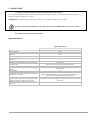
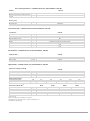
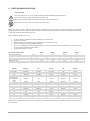
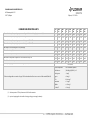
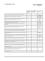
2.2. Commission Regulation (EU) No 327/2011
VENTILATION DEVICES:
Supply / Exhaust fan
Cube R8
Fans quantity
1
Overall efficiency
70,3 %
Measurement category used to determine energy
efficiency
static
Efficiency category
A
Efficiency grade in optimal point of energy
efficiency
79,8 %
Integrated EC controller
Manufacturer’s trademark, trade registry number,
production site.
Ziehl-Abegg,
NIP: 527-23-34-309, Regon 017239920, Germany
Product’s model number
ECblue
Rotations per minute at optimal point of energy
efficiency
2400 rev/min
Specific ratio
1,0
Information essential for dismantling, recycling or
removing after operation
Dismantling process should be made by a person with appropriate
qualifications. Dismantling and recycling process should be done in
agreement with certified waste management unit.
Information essential for minimum environmental
impact and assuring optimal operation time with
regard to installation, operation and fan use
Periodic warranty inspections must be conducted as well as later
maintenance inspections. Regulations mentioned in user’s manual must
be obeyed.
Additional elements to determine fan’s energy
efficiency
N/A

10 |www.flowair.com
3. GENERAL INFORMATION
3.1. Cube application
The Cube unit, due to its compact construction, has all modules for full air processing like air condition and ventilation.
Depending on unit’s type and size, Cube can be used for air recovery ventilation, heating and cooling in buildings like:
• large industrial buildings.: production or storage halls, printeries, logistic centers,
• commercial buildings (shopping malls, supermarkets, petrol stations, car showrooms),
• public buildings such as: cinemas, theatres, gyms,
• restaurants or fast-food places.
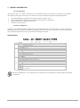
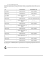
3.2. Device configuration
Cube units can be additionally equipped with heater to increase the temperature of air at outlet. There is a water, electric or gas
modulating heater and an option of a reversible heat pump paired with an electric, water or gas heater. Unit’s size, together with
types and optional equipment creates range described according to chart below:
COOLING DEVICES:
1
Nominal cooling capacity
2
Heat recovery
R
Rotational exchanger
B
No heat recovery
3
Type of heater/cooler
N
No additional heater / cooler
W
Water heater
G
Gas heater
E
Electric heater
HP
Reversible heat pump
C
Water cooler
4
Non-standard
Wx
x-row water heat exchanger
Gmxx
Modulated gas heater (capacity xx)
Exx
Electric heater(capacity xx)
XXYY
Class filter: XX - supply, YY - exhaust
L
Heat recovery module(Cube 80/100)
REC
Execution without exhaust fans
JRN
One-way ventilation system (JRN – fresh and recirculating air; JR – recirculating air;
JN – fresh air)
JR
JN
Full unit’s configuration is set on ordering process, leaded by our Sales Department or Project Support Department
consultations.

www.flowair.com | 11
VENTILATION DEVICES:
1
Heat recovery
R
Rotary heat exchanger
B
No heat recovery
2
Nominal airflow[m3/h *10^3]
3
Type of heater/cooler
N
No additional heater / cooler
W
Water heater
G
Gas heater
E
Electric heater
C
Water cooler
DX
Cooling freon exchanger
DXHP
Cooling and heating freon exchanger
4
Non-standard
Wx
x-row water heat exchanger
Gmxx
Modulated gas heater (capacity xx)
Exx
Electric heater (capacity xx)
XXYY
Non-standard filter XX – supply filter class, YY – exhaust filter class
L
External heat recovery module (Cube 80/100)
REC
Unit without exhaust fans
JRN
One-way ventilation system (JRN – fresh and recirculating air; JR – recirculating air;
JN – fresh air)
JR
JN
SUPPLY MODULE CONFIGURATION:
1
Roof base
NWS
Roof base for Cube R8 i Cube 20
NWL
Roof basefor Cube 40
2
Water heater
N
No additional heater
W2
2-row water heater
W3
3-row water heater
3
Supply module
D
Swirl diffuser with actuator
V
Ventilation ducts connections
3J
Long range nozzles
Full unit’s configuration is set on ordering process, leaded by our Sales Department or Project Support Department
consultations.

12 |www.flowair.com
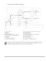
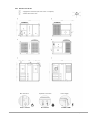
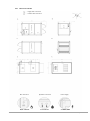
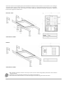
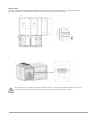
3.3. General characteristics construction Cube 20
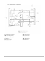
3.4. General characteristics construction Cube 40
1. Supply fan EC
2. Exhaust fan EC
3. Compressor cycle fan
4. Water heat exchanger (Cube – W)
5. Circulating pump (Cube – W)
6. 3-way valve (Cube – W)
7. Electric heater (Cube – E) / Gas heater (Cube – G)
8. Fresh air filter
9. Exhaust filter
10. Recirculation damper (economizer)
11. Rotary heat exchanger
12. Compressor
13. External compressor cycle heat exchanger
14. Internal compressor cycle heat exchanger
15. Crane holders

www.flowair.com | 13
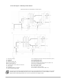
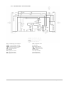
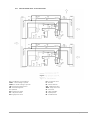
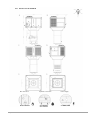
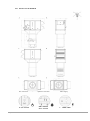
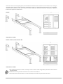
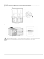
3.5. General characteristics construction Cube 50 – 100
1. Supply fans EC
2. Exhaust fans EC
3. Compressor cycle fans
4. Water heat exchanger (Cube – W)
5. Circulating pump (Cube – W)
6. 3-way valve (Cube – W)
7. Electric heater (Cube – E) / Gas heater (Cube – G)
8. Fresh air filter
9. Exhaust filter
10. Recirculation damper (economizer)
11. Rotary heat exchanger
12. Compressor
13. External compressor cycle heat exchanger
14. Internal compressor cycle heat exchanger
15. Crane holders

14 |www.flowair.com
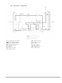
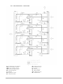
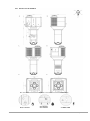
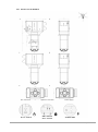
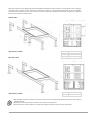
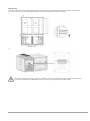
3.6. General characteristics construction Cube 120/160
1. Supply fans EC
2. Exhaust fans EC
3. Compressor cycle fans
4. Water heat exchanger (Cube – W)
5. Circulating pump (Cube – W)
6. 3-way valve (Cube – W)
7. Electric heater (Cube – E) / Gas heater (Cube – G)
8. Fresh air filter
9. Exhaust filter
10. Recirculation damper (economizer)
11. Rotary heat exchanger
12. Compressor
13. External compressor cycle heat exchanger
14. Wymiennik ciepła wewnętrznego obiegu
15. Crane holders

www.flowair.com | 15
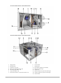
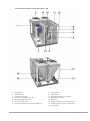
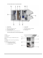
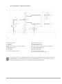
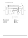
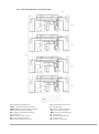
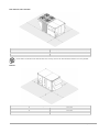
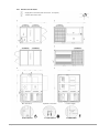
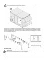
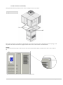
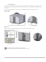
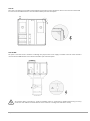
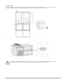
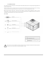
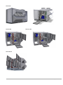
3.7. General characteristics construction Cube R8
1. Supply fans EC
2. Exhaust fans EC
3. Water heat exchanger (Cube – W)
4. Circulating pump (Cube – W)
5. 3-way valve (Cube – W)
6. Electric heater (Cube – E) / Gas heater (Cube – G)
7. Fresh air filter
8. Exhaust filter
9. Recirculation damper (economizer)
10. Rotary heat exchanger
11. Crane holders
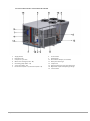
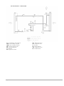
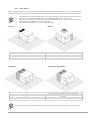
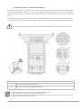
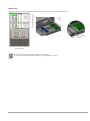
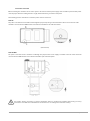
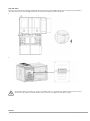
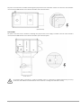
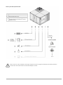
3.8. General characteristics construction supply module
1. Roofing
2. Acoustic silencers
3. Connections
4. Water heat exchanger in the NW module (option)
5. Base
6. Isolation
7. Connection of water heat exchanger with mixing
cycle (option)
8. Possible supply module configurations
• D - swirl diffuser with actuator
• V - ventilation ducts connections
• 3J - long range nozzles

16 |www.flowair.com
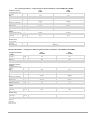
4. TECHNICAL DATA
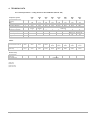
4.1. Technical parameters – cooling devices for duct installation (Cube 20 -160)
Compressor system
Cube
20
Cube
40
Cube
50
Cube
60
Cube
80
Cube
100
Cube
120
Cube
160
Thermodynamic power
- cooling
(1)
kW 19,9 38,2 57,5 65,2 80,8 91,4 132,0 156,8
EER (1)
-
3,24
3,03
3,42
3,42
3,45
3,28
3,56
3,36
SEER(on) (2)
-
5,73
4,09
4,14
4,07
4,12
3,97
4,38
4,19
Energetic efficiency (3)
%
210,5
152,8
153,7
151,6
154,0
148,7
165,4
158,0
Compressor type -
scroll,
inverter
scroll,
tandem
scroll,
multicicuit
Compressors quantity
-
1
2
2
2
2
2
4
4
Circuits quantity
-
1
1
2
2
2
2
4
4
Power range % 40 - 100 50, 100 50, 100 50, 100 50, 100 50, 100
25, 50, 75,
100
25, 50, 75,
100
Refrigerant
R410A
Refrigerant quantity
kg
5,5
9,5
2x8,8
2x8,8
2x9,1
2x9,1
4x9,0
4x9,1
Airflow
Total air flow / Fresh air m3/h 5500 8000 14000
16000
/
15000
19000
/
17000
21000
/
17000
24000
/
20000
28000
/
20000
Minimum cooling
efficiency
m3/h 3000 6000 10500 12000 13500 15750 21000 21000
Heat recovery
Heat recovery
efficiency
(4)
m3/h >78,5 >73,1 >73,7 >73,0 >73,3 >73,3 >73,0 >73,0
Exchanger type
-
rotational
(1) EN 14511
(2) EN14825
(3) UE 2016/2281
(4) UE 1253/2014

www.flowair.com | 17
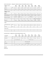
General technical data – cooling devices with heat pump for duct installation (Cube 20 – 160 HP)
Compressor system -
cooling
Cube
20 HP
Cube
40 HP
Cube
50 HP
Cube
60 HP
Cube
80 HP
Cube
100 HP
Cube
120 HP
Cube
160 HP
Thermodynamic power -
cooling
(1)
kW 19,8 38,2 56,8 64,4 79,6 90,3 130,3 154,8
EER netto(1)
-
3,13
2,96
3,87
3,37
3,38
3,25
3,51
3,31
SEER(on) (2)
-
5,63
4,08
4,11
4,02
4,07
3,91
4,33
4,13
Energetic efficiency (3)
%
206,7
152,4
152,6
149,6
152,1
146,3
163,1
155,6
Compressor system -
heating
Thermodynamic power –
heating
(1)
kW 20,2 40,9 53,9 61,4 76,5 87 126,8 152
COP
(1)
-
4,05
3,63
3,76
3,76
3,91
3,85
3,8
3,75
SCOP(on)
(2)
-
4,53
3,55
3,34
3,33
3,49
3,44
3,56
3,52
Energetic efficiency
(3)
%
172,8
133,6
125,5
125,2
131,4
129,4
134,0
132,7
Compressor type -
scroll,
inverter
scroll,
tandem
scroll,
multicicuit
Compressors quantity
-
1
2
2
2
2
2
4
4
Circuits quantity
1
1
2
2
2
2
4
4
Power range % 40 -100 50, 100 50, 100 50, 100 50, 100 50, 100
25, 50, 75,
100
25, 50, 75,
100
Refrigerant
R410A
R410A
R410A
R410A
R410A
R410A
R410A
R410A
Refrigerant quantity
kg
5,9
9,5
2x9,3
2x9,3
2x9,6
2x9,6
4x9,5
4x9,6
Airflow
Total air flow / Fresh air m3/h
do
5500
do
8000
do
14000
do 16000
/
do 15000
do 19000
/
do 17000
do 21000
/
do 17000
do 24000
/
do 20000
do 28000
/
do 20000
Minimum cooling
efficiency
m3/h 3000 6000 10500 12000 13500 15750 21000 21000
Heat recovery
Heat recovery efficiency(4)
m3/h
>78,5 >73,1 >73,7 >73,0 >73,3 >73,3 >73,0 >73,0
Exchanger type -
rotational
Construction data – cooling devices for duct installation (Cube 20 – 160)
Construction
Cube
20 (HP)
Cube
40 (HP)
Cube
50 (HP)
Cube
60 (HP)
Cube
80 (HP)
Cube
100 (HP)
Cube
120 (HP)
Cube
160 (HP)
Outlet channels
connection mm
900x
500
900x
500
1400x
500
1400x
500
1500x
500
1500x
500
1600x
650
1600x
650
Exhaust channels
connection
mm
900x
500
900x
500
1400x
500
1400x
500
1500x
500
1500x
500
1600x
500
1600x
500
Filters -
pocket
Coarse 80% (~G4)
cassete
Coarse 80% (~G4)
Thermal insulation class
-
M0
Casing / middle panel
color
- RAL 7035 /RAL 7024
Casing
-
insulated panels with 50 mm mineral wool
Main frame
-
steel, integrated
Weight kg
>650
<850
>900
<1100
>1315
<1550
>1350
<1600
>1600
<1990
>1700
<2250
>1800
<2250
>1930
<2350
(1) EN 14511
(2) EN14825
(3) UE 2016/2281
(4) UE 1253/2014

18 |www.flowair.com
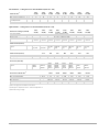
Electrical data – cooling devices for duct installation (Cube 20 – 160)
Electrical data (1)
Cube
20 (HP)
Cube
40 (HP)
Cube
50 (HP)
Cube
60 (HP)
Cube
80 (HP)
Cube
100 (HP)
Cube
120 (HP)
Cube
160 (HP)
Max. power consumption
kW
15
25
34
39
54
59
72
100
Max. current consumption
A
27
45
63
72
92
107
135
173
Start-up current
consumption LRA
A 12 129 171 186 188 242 246 255
Power supply
V/Hz
3x400/50
Optional data – cooling devices for duct installation (Cube 20 – 160)
Water heat exchanger (Cube W)
Cube
20 (HP)
Cube
40 (HP)
Cube
50 (HP)
Cube
60 (HP)
Cube
80 (HP)
Cube
100 (HP)
Cube
120 (HP)
Cube
160 (HP)
Type of exchanger
-
water exchanger, 2-row
Nominal heating power (2)
kW
55
74
111
120
158
167
182
199
Pressure drop
-
0 – built-in circulation pump
Connection ″
G 1″
internal
G 1″
internal
G 1 1/4″
internal
G 1 1/4″
internal
G 1 1/4″
internal
G 1 1/4″
internal
G 1 1/4″
internal
G 1 1/4″
internal
Electric heater (Cube E)
Option - E15, E23,
E30, E45
E15, E23,
E30, E45
E15, E30,
E45, E60,
E75
E15, E30,
E45, E60,
E75
E30, E45,
E60, E75,
E90
E30, E45,
E60, E75,
E90
E30, E45,
E60, E75,
E90
E30, E45,
E60, E75,
E90
Electric heater (Cube E)
E15
E23
E30
E45
E60
E75
E90
Nominal heating power
kW
15,0
22,5
30,0
45,0
60,0
75,0
90,0
Heating degrees - 2 3 3 3 3
3
4
Gas heater (Cube Gm)
Option - Gm20,
Gm34
Gm20,
Gm34,
Gm45
Gm45,
Gm65,
Gm80,
Gm105
Gm45,
Gm65,
Gm80,
Gm105
Gm45,
Gm65,
Gm80,
Gm105
Gm45,
Gm65,
Gm80,
Gm105
Gm65,
Gm80,
Gm105
Gm65,
Gm80,
Gm105
Gas heater technical data (3)
Gm20 Gm34 Gm45 Gm65 Gm80 Gm105
Nominal heating power
kW
18,2
33,6
40,5
62,9
80
97,2
Gas consumption (G20)
m3/h
2,01
3,69
4,44
6,88
8,68
10,58
Flue gas exhaust system
-
integrated
Gas connection
″
GZ 3/4”
GZ 3/4”
GZ 3/4”
GZ 3/4”
GZ 3/4”
GZ 3/4”
Minimum air flow
m3/h
3000
3500
4200
6500
8200
10000
(1) It does not apply to devices with an electric heater.
(2) Heating factor's temperature 70/50°C and inlet air temperature 8°
(3) Data refer to G20 gas supply

www.flowair.com | 19
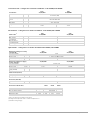
4.2. Technical parameters – ventilation devices for duct installation - Cube R8
Air flow
Cube R8
Total air flow / Fresh air
m3/h
up to 8000
External pressure drop for the 8000 m3/h
air flow
m3/h 350
Heat recovery
Heat recovery efficiency
(1)
m3/h
>73,1
Exchanger type -
rotational
Construction data – ventilation devices for duct installation - Cube R8
Construction
Cube R8
Outlet channels connection
mm
900x500
Exhaust channels connection
mm
900x500
Filters (supply/exhaust)
-
ePM2,5 65% (~F7) / ePM10 50% (~M5)
Thermal insulation class
-
M0
Casing / middle panel color
-
RAL 7035 /RAL 7024
Casing
-
insulated panels with 50 mm mineral wool
Main frame
-
steel, integrated
Weight kg
>650
<800
Electrical data – ventilation devices for duct installation - Cube R8
Electrical data( (2)
Cube R8
Max. power consumption
kW
7
Max. current consumption
A
11
Power supply
V/Hz
3x400/50
Optional data – ventilation devices for duct installation - Cube R8
Water heat exchanger (Cube W)
Cube R8
Type of exchanger
-
water exchanger, 2-row
Nominal heating power (3)
kW
74
Pressure drop
-
0 – built-in circulation pump
Connection
″
G 1″ internal
Electric heater (Cube E)
E15 E23 E30 E45 E60
Nominal heating power
kW
15,0
22,5
30,0
45,0
60,0
Heating degrees - 2 3 3 3 3
Gas heater technical data (4)
Gm20 Gm34 Gm45 Gm65
Nominal heating power
kW
18,2
33,6
40,5
62,9
Gas consumption (G20)
m3/h
2,01
3,69
4,44
6,88
Flue gas exhaust system
-
integrated
Gas connection
″
GZ 3/4”
GZ 3/4”
GZ 3/4”
GZ 3/4”
Minimum air flow
m3/h
3000
3500
4200
6500
(1) UE 1253/2014
(2) it does not apply to devices with an electric heater
(3) heating factor's temperature 70/50°C and inlet air temperature 8°C
(4) data refer to G20 gas supply

20 |www.flowair.com
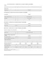
4.3. Technical parameters – cooling devices for ductless instalation – Cube 20 NWS; Cube 40 NWL
Compressor system
Cube
20 NWS
Cube
40 NWL
Thermodynamic power
- cooling
(1)
kW 19,9 38,2
EER (1)
-
3,24
3,03
SEER(on) (2)
-
5,73
4,09
Energetic efficiency
(3)
%
210,5
152,8
Compressor type -
scroll,
inverter
scroll,
tandem
Compressors quantity
-
1
2
Circuits quantity
-
1
1
Power range
%
40 - 100
50, 100
Refrigerant
R410A
R410A
Refrigerant quantity
kg
5,7
8,6
Airflow
Total air flow / Fresh air
m3/h
do 5500
do 8000
Minimum cooling
efficiency
m3/h 3000 6000
Heat recovery
Heat recovery
efficiency
(4)
m3/h >78,5 >73,1
Exchanger type
-
rotational
General technical data – cooling devices with heat pump for ductless installation – Cube 20 NWS; Cube 40 NWL
Compressor system -
cooling
Cube
20 HP NWS
Cube
40 HP NWL
Thermodynamic power -
cooling
(1)
kW 19,8 38,2
EER (1)
-
3,13
2,96
SEER(on)
(2)
-
5,63
4,08
Energetic efficiency
(3)
%
206,7
152,4
Compressor system -
heating
Thermodynamic power –
heating
(1)
kW 20,2 40,9
COP
(1)
-
4,05
3,63
SCOP(on) (2)
-
4,53
3,55
Energetic efficiency 3)
%
172,8
133,6
Compressor type -
scroll,
inverter
scroll,
tandem
Compressors quantity
-
1
2
Circuits quantity
1
1
Power range
%
40 -100
50, 100
Refrigerant
R410A
R410A
Refrigerant quantity
kg
5,9
8,6
Airflow
Total air flow / Fresh air
m3/h
do 5500 do 8000
Minimum cooling
efficiency
m3/h 3000 6000
Heat recovery
Heat recovery
efficiency
(4)
m3/h >78,5 >73,1
Exchanger type
-
rotational
(1) EN 14511
(2) EN14825
(3) UE 2016/2281
(4) UE 1253/2014
Strona się ładuje...
Strona się ładuje...
Strona się ładuje...
Strona się ładuje...
Strona się ładuje...
Strona się ładuje...
Strona się ładuje...
Strona się ładuje...
Strona się ładuje...
Strona się ładuje...
Strona się ładuje...
Strona się ładuje...
Strona się ładuje...
Strona się ładuje...
Strona się ładuje...
Strona się ładuje...
Strona się ładuje...
Strona się ładuje...
Strona się ładuje...
Strona się ładuje...
Strona się ładuje...
Strona się ładuje...
Strona się ładuje...
Strona się ładuje...
Strona się ładuje...
Strona się ładuje...
Strona się ładuje...
Strona się ładuje...
Strona się ładuje...
Strona się ładuje...
Strona się ładuje...
Strona się ładuje...
Strona się ładuje...
Strona się ładuje...
Strona się ładuje...
Strona się ładuje...
Strona się ładuje...
Strona się ładuje...
Strona się ładuje...
Strona się ładuje...
Strona się ładuje...
Strona się ładuje...
Strona się ładuje...
Strona się ładuje...
Strona się ładuje...
Strona się ładuje...
Strona się ładuje...
Strona się ładuje...
Strona się ładuje...
Strona się ładuje...
Strona się ładuje...
Strona się ładuje...
Strona się ładuje...
Strona się ładuje...
Strona się ładuje...
Strona się ładuje...
Strona się ładuje...
Strona się ładuje...
Strona się ładuje...
Strona się ładuje...
Strona się ładuje...
Strona się ładuje...
Strona się ładuje...
Strona się ładuje...
Strona się ładuje...
Strona się ładuje...
Strona się ładuje...
Strona się ładuje...
Strona się ładuje...
Strona się ładuje...
Strona się ładuje...
Strona się ładuje...
Strona się ładuje...
Strona się ładuje...
Strona się ładuje...
Strona się ładuje...
Strona się ładuje...
Strona się ładuje...
Strona się ładuje...
Strona się ładuje...
Strona się ładuje...
Strona się ładuje...
Strona się ładuje...
Strona się ładuje...
Strona się ładuje...
Strona się ładuje...
Strona się ładuje...
Strona się ładuje...
Strona się ładuje...
Strona się ładuje...
Strona się ładuje...
Strona się ładuje...
Strona się ładuje...
Strona się ładuje...
Strona się ładuje...
Strona się ładuje...
-
 1
1
-
 2
2
-
 3
3
-
 4
4
-
 5
5
-
 6
6
-
 7
7
-
 8
8
-
 9
9
-
 10
10
-
 11
11
-
 12
12
-
 13
13
-
 14
14
-
 15
15
-
 16
16
-
 17
17
-
 18
18
-
 19
19
-
 20
20
-
 21
21
-
 22
22
-
 23
23
-
 24
24
-
 25
25
-
 26
26
-
 27
27
-
 28
28
-
 29
29
-
 30
30
-
 31
31
-
 32
32
-
 33
33
-
 34
34
-
 35
35
-
 36
36
-
 37
37
-
 38
38
-
 39
39
-
 40
40
-
 41
41
-
 42
42
-
 43
43
-
 44
44
-
 45
45
-
 46
46
-
 47
47
-
 48
48
-
 49
49
-
 50
50
-
 51
51
-
 52
52
-
 53
53
-
 54
54
-
 55
55
-
 56
56
-
 57
57
-
 58
58
-
 59
59
-
 60
60
-
 61
61
-
 62
62
-
 63
63
-
 64
64
-
 65
65
-
 66
66
-
 67
67
-
 68
68
-
 69
69
-
 70
70
-
 71
71
-
 72
72
-
 73
73
-
 74
74
-
 75
75
-
 76
76
-
 77
77
-
 78
78
-
 79
79
-
 80
80
-
 81
81
-
 82
82
-
 83
83
-
 84
84
-
 85
85
-
 86
86
-
 87
87
-
 88
88
-
 89
89
-
 90
90
-
 91
91
-
 92
92
-
 93
93
-
 94
94
-
 95
95
-
 96
96
-
 97
97
-
 98
98
-
 99
99
-
 100
100
-
 101
101
-
 102
102
-
 103
103
-
 104
104
-
 105
105
-
 106
106
-
 107
107
-
 108
108
-
 109
109
-
 110
110
-
 111
111
-
 112
112
-
 113
113
-
 114
114
-
 115
115
-
 116
116


flowair Cube R8 Instrukcja obsługi
- Kategoria
- Klimatyzatory typu split
- Typ
- Instrukcja obsługi
- Niniejsza instrukcja jest również odpowiednia dla
w innych językach
- English: flowair Cube R8 User manual
Inne dokumenty
-
 SolarPower SP4002 Installation and Owner's Manual
-
 Lyson W4097 Instrukcja obsługi
-
Dometic RM 7400(L) Instrukcja obsługi
-
Tesla Air to Water Heat Pump-TGTP-14HMDA1 Instrukcja obsługi
-
TOPMET CABI12 DUO E Instrukcja obsługi
-
Ferplast Star 120 Instrukcja obsługi
-
BOMANN EWB 6068 CB Instrukcja obsługi
-
Electrolux ERB2623 Instrukcja obsługi
-
Konica Minolta JACK Instrukcja obsługi
-
ProfiCook PC-EWB 1253 Instrukcja obsługi

