Samsung SCC-C4207P Instrukcja obsługi
- Kategoria
- Kamery ochrony
- Typ
- Instrukcja obsługi
Niniejsza instrukcja jest również odpowiednia dla

E
CODE : AB68-00545A(00)
Printed in China
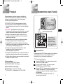
✽ Be sure to read the "Safety Precautions" in this manual
to ensure correct use and operation of this product.
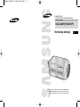
320X POWER ZOOM WDR CAMERA
SCC-C4207(P)/C4307(P)
RU
PL
Owner’s Instructions
êÛÍÓ‚Ó‰ÒÚ‚Ó ÔÓθÁÓ‚‡ÚÂÎfl
Instrukcja obs∏ugi
00544A_C4207(P)-E+R+P 6/5/06 10:29 AM ˘` a

1
E
Safety Precautions
Important Safety Instructions
2
The purpose of safety precautions is to prevent accidental
injury or property damage. Always observe all safety
precautions.
❖ The precautions are divided into "Warnings" and
"Cautions" as distinguished below:
Warning
Ignoring this precaution
may result in death or
serious injury.
Caution
Ignoring this precaution
may result in injury or
damage to property.
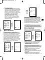
Warnings
1. Be sure to use only the standard adapter which is
specified in the specification sheet.
Using any other adapter could cause fire, electrical
shock, or damage to the product.
2. Check the external connection terminals first before
connecting the power source and signal wires.
Connect the alarm signal wires to the alarm terminals.
Connect the DC12V power adapter to the SCC-
C4207(P) power input, making
sure that the currect polarity is observed.
Connect the DC12V or AC24V power adapter to the
SCC-C4307(P) power input.
3. Do not connect multiple cameras to a single adapter.
(Exceeding the capacity may cause abnormal heat
generation or fire.)
1. Read these instructions.
2. Keep these instructions.
3. Heed all warnings.
4. Follow all instructions.
5. Do not use this apparatus near water.
6. Clean only with dry cloth.
7. Do not block any ventilation openings, Install in
accordance with the manufacturer's instructions.
8. Do not install near any heat sources such as radiators,
heat registers, or other apparatus (including amplifiers) that
produce heat.
9. Do not defeat the safety purpose of the polarized or
grounding- type plug. A polarized plug has two blades with
one wider than the other.
A grounding type plug has two blades and a third
grounding prong.
The wide blade or the third prong are provided for your
safety. If the provided plug does not fit into your outlet,
consult an electrician for replacement of the obsolete
outlet.
10. Protect the power cord from being walked on or pinched
particularly at plugs, convenience receptacles, and the
point where they exit from the apparatus.
11. Only use attachments/accessories specified by the
manufacturer.
12. Use only with cart, stand, tripod, bracket, or table specified
by the manufacturer, or sold with the apparatus.
13. Unplug this apparatus. When a cart is used, use caution
when moving the cart/apparatus combination to avoid
injury from tip-over.
14. Refer all servicing to qualified service personnel. Servicing
is required when the apparatus has been damaged in any
way, such as power-supply cord or plug is damaged, liquid
has been spilled or objects have fallen into the apparatus
the apparatus has been exposed to rain or moisture, does
not operate normally, or has been dropped.
00544A_C4207(P)-E+R+P 6/5/06 10:29 AM ˘` 1

4
E
3
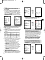
Cautions
1. Do not drop objects on the product or apply strong shock
to it. Keep away from a location subject to excessive
vibration or magnetic interference.
2. Do not install in a location subject to high temperature,
low temperature, or high humidity. (Doing so may cause
fire or electrical shock.)
3. Avoid a location which is exposed to direct sunlight, or
near heat sources such as heaters or radiators.
(Neglecting to do so may result in a risk of fire.)
4. If you want to relocate the already installed product, be
sure to turn off the power before moving or reinstalling it.
5. Install in a well-ventilated location.
6. Remove the power plug from the outlet when there is a
lightning storm. (Neglecting to do so may cause fire or
damage to the product.)
4. Securely plug the power cord into the power receptacle.
(A loose connection may result in fire.)
5. When mounting the camera on a wall or ceiling, fasten it
safely and securely. (A falling camera may cause
personal injury.)
6. Do not place conductive objects (e.g., screwdrivers,
coins, and metal things) or containers filled with water on
top of the camera.
(Serious injury may result from fire, electrical shock, or
falling objects.)
7. Do not install the unit in humid, dusty, or sooty locations.
(Doing so may cause fire or electrical shock.)
8. If any unusual smells or smoke come from the unit, stop
using the product. In such case, immediately disconnect
the power source and contact the service center.
(Continued use in such a condition may cause fire or
electrical shock.)
9. If this product fails to operate normally, contact the store
of purchase or your nearest service center. Never
disassemble or modify this product in any way.
(Problems caused by unauthorized user disassembly or
repairs are not covered by your warranty.)
10. When cleaning, do not spray water directly onto parts of
the product. (Doing so may cause fire or electrical
shock.) Gently wipe the surface with a dry cloth. Never
use detergents or chemical cleaners on the product, as
this may result in discoloration of surface or cause
damage to the finish.
00544A_C4207(P)-E+R+P 6/5/06 10:29 AM ˘` 3

5
E
6
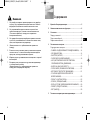
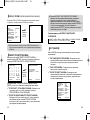
Contents
1. Overview.............................................................7
2. Part Names and Functions ...............................8
3. Installation........................................................11
Checking the Package Contents .......................11
Preparing the Cables ........................................12
Connecting the Cables ......................................13
4. Navigating the Setup Menu.............................15
Structure of the Setup Menu .............................15
- CAMERA ID.....................................................16
- IRIS..................................................................16
- SHUTTER........................................................19
- FLICKERLESS ................................................20
- AGC/MOTION ................................................21
- WHITE BAL .....................................................22
- FOCUS MODE ................................................23
- MOTION DET ..................................................23
- COLOR / BW ...................................................25
- PRIVACY.........................................................27
- SPECIAL .........................................................28
- DISPLAY ZOOM..............................................31
- PRESET ..........................................................31
- EXIT.................................................................32
5. Product Specification .....................................33
FCC Statement
This device complies with Part 15 of the FCC Rules.
Operation is subject to the following two conditions:
(1) This device may not cause harmful interference, and
(2)
This device must accept any interference received,
including interference that may cause undesired operation.
Note:
This equipment has been tested and found to comply with
the limits for Class B digital devices, pursuant to Part 15 of
the FCC rules. These limits are designed to provide
reasonable protection against harmful interference in a
residential installation. This equipment generates, uses and
can radiate radio frequency energy and, if not installed and
used in accordance with the instructions, may cause harmful
interference to radio communications. However, there is no
guarantee that interference will not occur in a particular
installation. If this equipment does cause harmful
interference to radio or television reception, which can be
determined by turning the equipment off and on, the user is
encouraged to try to correct the interference by one or more
of the following measures:
- Reorient or relocate the receiving antenna
- Increase the separation between the equipment and
receiver
- Connect the equipment into an outlet on a circuit different
from that to which the receiver is connected
- Consult the dealer or an experienced radio/TV technician
for help Use of shielded cable is required to comply with
Class B limits in Subpart B of Part 15 of the FCC rules.
Do not make any changes or modifications to the
equipment unless otherwise specified in the manual.
If such changes or modifications should be made, you
could be required to stop operation of the equipment.
00544A_C4207(P)-E+R+P 6/5/06 10:29 AM ˘` 5

7
Overview
1
8
Part Names and Functions
2
E
This is a state-of-art WDR zoom camera which employed the
x32 zoom lens and digital zoom IC to monitor up to 320 times
as large as an original image.
SCC-C4207(P)/C4307(P) has the following functions.
●
WDR for distinct photographing of both bright and dark
parts of an image.
●
DAY/NIGHT to raise the sensitivity by automatic
conversion into the White & Black mode at night or in poor
illumination environment.
●
Low - Light Surveillance function that enables image
capture even under extremely low light conditions.
●
White Balance function that provides accurate color
rendition under any light conditions.
●
BLC function that enables effective back light
compensation even under a spotlight or a very bright
incident light.
●
Auto Focus function that automatically tracks and focuses
on the moving subject.
●
Privacy Zone function to hide a special area for privacy
protection.
●
RS485/ Wired remote control function.
Broadcast System
●
SCC-C4207/4307 : NTSC System
●
SCC-C4207P/4307P : PAL System
Power System/Power Consumption
●
SCC-C4207(P): DC 12V/5.5W
●
SCC-C4307(P): AC 24V, DC 12V/6W
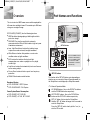
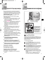
REMOTE RS-485 PWR IN
SET-UP button
The function of the SET-UP button varies depending on
whether you are currently in Normal Operation mode (i.e.,
the Setup Menu is not displayed) or Setup Menu mode.
✔
In Normal Operation Mode
- UP/ DOWN buttons : Use as the ZOOM Tele button
and the ZOOM Wide button respectively.
- LEFT/ RIGHT buttons : Use as the FOCUS Near
button and the FOCUS Far button respectively.
- SET- UP button: Use to enter the Setup Menu.
Hold the SET- UP button for longer than 3 seconds to
enter the Setup Menu.
Press the [SET UP] switch shortly (within 1 sec.) to
start the AF function.
SET-UP button
Instead of “POWER”, “DC IN”
is writtern in SCC-C4207(P).
Instead of “POWER”, “PWR
IN” and instead of “GND”,
“DC12&AC24V” is writtern in
SCC-C4307(P).
00544A_C4207(P)-E+R+P 6/5/06 10:29 AM ˘` 7

E
109
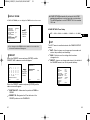
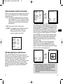
✔
In Setup Menu Mode
- UP/ DOWN buttons: Use to move the cursor up or down.
- LEFT/ RIGHT buttons: Use to move the cursor left or
right, or to sequentially view the values that can be
assigned to a parameter.
- ENTER button: Use to select a Sub Menu item, and to
accept the current value.
ZOOM/ FOCUS REMOTE terminals
This port is used for ZOOM/FOCUS, MENU CONTROL,
HOME RETURN, and AF by using an external controller.
Depending on the input condition, 4 modes, A, B, C, and
D are available. (SPECIAL - CTRL TYPE)
(Operation Voltage Range : +3V~+13V, -3V~-13V)
1)
When the voltage is supplied to either ZOOM or FOCUS port,
❖ 1: During MENU OFF, controls ZOOM/FOCUS and
during MENU ON, changes the direction, Up, Down,
Left, and Right.
2) When the voltage is supplied to both ports
❖ 2: For short voltage supply during MENU OFF,
executes AF and for more than 2 second
❖ 3: For more than 2 second long voltage supply, moves
to the PRESET 0(HOME) position.
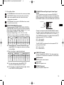
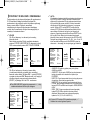
DAY/NIGHT External Signal Input & Alarm Signal
Output
This is a function to receive the external DAY/NIGHT
signal from the sensor(option) and convert the signal into
BW. An alarm signal is output from this terminal when the
MOTION DET mode is activated or BW mode is activated.
Connect an external sensor to the DAY/NIGHT terminal
as shown in
➀
then connect any external device such as
a buzzer or lamp to the ALARM terminal as shown in
➁
.
The ALARM output terminal is an open collector with the
following capacity: DC 16V and 100mA.
OFF : Open contact
ON : Below 100mA
The DAY/NIGHT input terminal has the input of DC 5V
pull-up and over 0.2mA.
OFF : Open contact
ON : Closed contact
VIDEO OUT terminal
Connect the monitor's VIDEO IN. The video signal from
the camera is transmitted to the monitor via this terminal.
RS485 terminal
RS485 remote control terminal.
Power LED
Lights when power is on.
POWER IN terminal
Plug in the power adapter here.
Function
❖ 1
A
B
C
D
TELE(Up)
-6V
-6V
+6V
+6V
ZOOM Port
FOCUS Port
WIDE(Down)
+6V
+6V
-6V
-6V
NEAR(Left)
-6V
+6V
-6V
+6V
FAR(Right)
+6V
-6V
+6V
-6V
Code
Function
A
B
C
D
-6V
-6V
+6V
+6V
ZOOM Port
FOCUS Port
ENTER/AF ❖ 2
HOME RETURN ❖ 3
ZOOM Port
FOCUS Port
-6V
+6V
-6V
+6V
+6V
+6V
-6V
-6V
+6V
-6V
+6V
-6V
Code
DAY/NIGHT IN
ALARM OUT
GND
1
2
00544A_C4207(P)-E+R+P 6/5/06 10:29 AM ˘` 9

E
12
To install and use the camera, first prepare the following
cables.
The requirements for the power adapter, which connects to
the camera's POWER IN terminal, are as follows:
●
SCC-C4207(P) : DC12V 600mA
●
SCC-C4307(P) : AC24V 300mA
DC12V 600mA
Video Cable
Use a BNC cable, such as the one shown below, to connect
the camera's VIDEO OUT to the monitor.
11
Installation
3
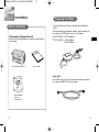
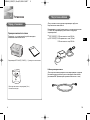
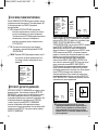
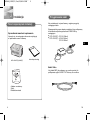
Checking the Package Contents
Make sure that the following accessories are included in
the package.
SCC-C4207(P)/4307(P)
User's Guide
Mount Adapter
Screw (2)
Terminal Block
Before Installation
Preparing the Cables
00544A_C4207(P)-E+R+P 6/5/06 10:29 AM ˘` 11

E
14
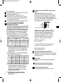
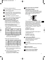
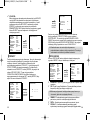
6. The requirements for RS485 control is as follows :
●
Signaling Speed: 9600 bps
●
Data Bit : 8 bits
●
Stop Bit : 1 bit
●
Parity Bit : none
SAMSUNG PROTOCOL
ADDRESS 0
TYPE
RS-485, HALF
BAUD RATE 9600
LENS OK
EEP VER 1.000
ROM VER 1.000
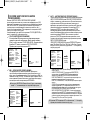
4. Determine the type of power supply and set the POWER
SELECTION switch accordingly. Next, plug the power
adapter into a wall outlet.
The requirements for the power adapter for each model are
as follows:
●
SCC-C4207(P) : DC12V 600mA
●
SCC-C4307(P) : AC24V 300mA
DC12V 600mA
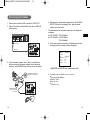
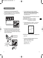
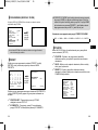
5. If the camera operates normally, the following screen will
be displayed for 5 seconds and then disappears.
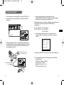
13
1. Connect one end of the BNC cable to the VIDEO OUT.
2. Connect the other end of the BNC cable to the VIDEO IN
of the monitor.
3.
Plug in the power adapter. Use a "minus" screwdriver to
connect one part of the power adapter, which consists of
two lines, to the POWER terminal of the camera as follows :
Video terminals on the back
of the monitor
BNC cable
POWER SELECTION switch
underneath the power adapte
POWER SELECTION
switch underneath the
power adapte
Connecting the Cables
❖
ROM VER and EEP VER may change without notice.
00544A_C4207(P)-E+R+P 6/5/06 10:29 AM ˘` 13

E
16
15
Navigating the Setup Menu
4
In this chapter, we will take a look at the menu system of the
SCC-C4207(P),C4307(P). First, we will take a look at the
structure of the Setup Menu and then describe the functions
of each menu item in the menu.
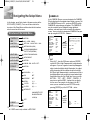
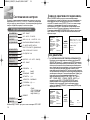
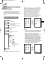
Structure of the Setup Menu
OFF/ON...
ALC.../WDR.../MANU...
OFF/1/100 ~ 1/10K/AUTO X2...~X160...
OFF/LOW/HIGH(AGC)
S.SLOW/SLOW/NORMAL/
FAST/F.FAST(MOTION)
ATW1/ATW2/AWC/MANU...
AF/MF/ONEAF
OFF/ON...
COLOR.../BW.../AUTO.../EXT...
OFF/ON...
PRIVACY
COLOR/BW
MOTION DET
FOCUS MODE
WHITE BAL
AGC/MOTION
SHUTTER
IRIS
CAMERA ID
...
POSI/NEGA +/-
DIS OFF
REVERSE OFF
DETAIL ( 1)-I-
Y-LEVEL ( 0)|--------
C-LEVEL ( 0)|--------
OTHER SET ...
LANGUAGE/CTRL TYPE/
RS-485/SYSTEM INFO/
V-SYNC(❖)
RET
...
EXIT
PRESET
SPECIAL
❖ V-SYNC menu is only available in SCC-C4307.
Press the
ENTER
button.
Press the
ENTER
button.
CAMERA ID OFF
IRIS ALC...
SHUTTER OFF
AGC LOW
WHITE BAL ATW
FOCUS MODE AF
MOTION DET OFF
COLOR/BW AUTO...
PRIVACY ...
SPECIAL ...
PRESET ...
EXIT QUIT
(IRIS/ALC)
BLC OFF
LEVEL (00) ----I----
RET
❙
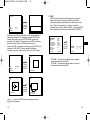
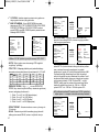
CAMERA ID
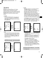
In the CAMERA ID menu, you may designate the CAMERA
ID to be displayed in the monitor connected to a camera. Set
the CAMERA ID menu to ON... and press [ENTER] and the
CAMERA ID setup submenu will appear. The CAMERA ID
may be created by up to 20 digits by using alphabets,
numbers, and some special texts served by the submenu
screen. You may locate the designated CAMERA ID on your
own by using the LOCATION... submenu.
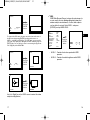
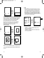
❙
IRIS
✔
ALC
Select ALC... from the IRIS menu and press [ENTER]
and the BLC(Back Light Compensation) setup submenu
will appear. If you use a general camera to photograph a
subject under backlight or bright illumination, the subject
will be shown dark on the monitor due to the backlight.
BLC(Back Light Compensation) is used to prevent such a
backlight problem to secure distinct images under bright
illumination. Using the [Left, Right] keys, you can set up
BOTTOM…, TOP…, LEFT…, RIGHT…, CENTER… 5
preset areas and the USER…function that can directly
set the areas. For example, for the items in the BLC
menu, you can confirm the preset BOTTOM area by
pressing [ENTER] key in the BOTTOM… status.
CAMERA ID ON...
IRIS ALC...
SHUTTER OFF
AGC LOW
WHITE BAL ATW1
FOCUS MODE AF
MOTION DET OFF
COLOR/BW AUTO...
PRIVACY OFF
SPECIAL ...
PRESET ...
EXIT QUIT
(CAMERA ID)
ABCDEFGH I JKL
MNOPQR ST U VWX
YZ0 123 456 789
.; ! -+
*
() /
SP
❿❿➛➛
SP
LOCATION...
RET
......................
00544A_C4207(P)-E+R+P 6/5/06 10:29 AM ˘` 15

E
1817
Press the
ENTER
button.
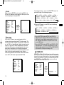
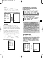
✔
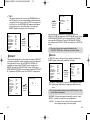
WDR
WDR(Wide Dynamic Range) enlarges the advantage of a
screen, mostly effective photographing both indoor and
outdoor subjects simultaneously. In short, both subjects
can be distinctly revived. Select WDR... and press
[ENTER] to set up WDR LEVEL.
- LEVEL 1 : Controls the shutter speed while WDR
operates.
- LEVEL 2 : Controls the whole brightness while WDR
operates.
CAMERA ID OFF
IRIS WDR...
SHUTTER OFF
AGC LOW
WHITE BAL ATW1
FOCUS MODE AF
MOTION DET OFF
COLOR/BW COLOR
PRIVACY OFF
SPECIAL ...
PRESET ...
EXIT QUIT
(IRIS/WDR)
LEVEL1 L --- I --- H
LEVEL2 L --- I --- H
RET
For items in the BLC menu, the user can set the size and location of
the BLC area by pressing [ENTER] key after put the cursor on
USER… using the [Left, Right] key. For SIZE items, you can use the
[Up, Down, Left, Right] key to designate the SIZE, and then press the
[ENTER] key. You can set the location for areas using the [Up, Down,
Left, Right] key in the LOCATION.
Use [Left, Right] key in the LEVEL menu to control the video
output level(brightness).
Press the
ENTER
button.
(IRIS/ALC)
BLC BOTTOM...
LEVEL (0) ----I----
RET
Press the
ENTER
button.
(IRIS/ALC)
BLC USER...
LEVEL (0) ----I----
RET
Press the
ENTER
button.
SIZE
LOCATION
SIZE
LOCATION
SIZE
LOCATION
00544A_C4207(P)-E+R+P 6/5/06 10:29 AM ˘` 17

20
E
19
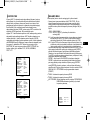
❙
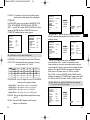
SHUTTER
In the SHUTTER menu, you may determine the fast
electronic shutter speed or slow AUTO shutter speed. The
fast electronic shutter supports 7 speeds from 1/100(1/120)
sec. to 1/10K sec. to photograph a bright and quick moving
image. The slow AUTO shutter supports about 10 speed
from x2 to x160 to make an image projected to the screen
more distinct and brighter by selecting the slow shutter
speed. If you want the camera to sense the brightness and
adjust the shutter speed accordingly, select a menu
commencing with Slow AUTO Shutter. When SHUTTER is
set to AUTO, AGC will be replaced with MOTION.
❙
FLICKERLESS
Either NTSC (for 50 Hz)or PAL (for 60 Hz areas)is an anti-flickering system
that is designed to avoid image flickering on the screen due to inconsistency
between the vertical synchronizing frequency of the picture and the flashing
frequency of the lightening. If you select and set AUTO to ON in SHUTTER
from VIDEO SET, you can set NTSC or PAL for your area and the auto
shutter speed is fixed at 1/100(1/120) second.
CAMERA ID OFF
IRIS ALC...
SHUTTER OFF
AGC LOW
WHITE BAL ATW1
FOCUS MODE AF
MOTION DET OFF
COLOR/BW COLOR
PRIVACY OFF
SPECIAL ...
PRESET ...
EXIT QUIT
➞
OFF ➞ AUTOX2...➞ AUTOX4...➞ AUTOX6...➞ AUTOX8...➞
AUTOX12...➞ AUTOX16...➞ AUTOX20...➞ AUTOX40...➞
AUTOX80...➞ AUTOX160...➞ OFF ➞ 1/100(120) ➞ 1/250 ➞
1/500 ➞ 1/1000 ➞ 1/2000 ➞ 1/4000 ➞ 1/10K ➞ OFF
If you keep pressing and ➞ in the SHUTTER menu, the
speed will change in the following sequence.
➞
❖When the IRIS mode is set to WDR, only the following
modes are available.
➞
OFF ➞ AUTOX2...➞ AUTOX4...➞ AUTOX6...➞ AUTOX8...➞
AUTOX12...➞ AUTOX16...➞ AUTOX20...➞ AUTOX40...➞
AUTOX80...➞ AUTOX160...➞ OFF
Press the
ENTER
button.
(MANUAL)
LEVEL (00) ----I----
RET
✔
MANU
When you press [ENTER] key after selecting MANU in the
IRIS item, an additional screen appears in which you can set
manually opening or closing the IRIS.
CAMERA ID OFF
IRIS MANU...
SHUTTER OFF
AGC LOW
WHITE BAL ATW
FOCUS MODE AF
MOTION DET OFF
COLOR/BW COLOR...
PRIVACY ...
SPECIAL ...
PRESET ...
EXIT QUIT
❈
If you set SHUTTER to between AUTO X4... and AUTO X128...,
FOCUS mode will be displayed as “MF“ (the product can operate only
in MF mode). You can ’t adjust the settings manually. If you set it to
OFF, 1/100(1/120)/10K or AUTO X2..., the product will recover the
previous FOCUS mode.
❈
If you set SHUTTER to between AUTO X2... and AUTO X128..., DIS
will be displayed as “---“ (it can only operate in Off mode). You can ’t
adjust the settings manually. If you set it to OFF or 1/100(1/120)/10K,
the product will recover the previous settings of DIS.
Press the
ENTER
button.
CAMERA ID OFF
IRIS ALC...
SHUTTER AUTO X2...
MOTION NORM
WHITE BAL ATW1
FOCUS MODE ONEAF
MOTION DET OFF
CLOLOR/BW COLOR...
PRIVACY OFF
SPECIAL ...
PRESET ...
EXIT QUIT
(FLICKERLESS)
FLICKERLESS OFF
RET
00544A_C4207(P)-E+R+P 6/5/06 10:29 AM ˘` 19

22
E
21
❙
WHITE BAL
You can select one of four modes for white balance adjustment as
follows:
- ATW1/ATW2(Auto-Tracing White Balance Mode): In these
modes, the color temperature is monitored continuously and
thereby white balance is set automatically. The following are the
approximate supported color temperature ranges in these modes.
ATW1 : 2500K ~ 9300K(✻1)
ATW2 : 2000K ~ 10000K(Mode recommended for sodium
lighting)(✻2)
✻ 1. If the color temperature is out of this range in ATW1 mode,
proper white balance may not be obtained. In that case,
select ATW2 mode.
✻ 2. In ATW2 mode, if one color is dominated in the shooted area,
the color can be displayed differently. Therefore, select the
mode which is appropriate for the environment.
- AWC(Auto-Tracing White Balance Control): In this mode, accurate
white balance is obtained by pressing [ENTER] while having a
white paper in front of the camera. White Balance data will be
maintained after set it once. AWC mode is best in locations where
the color temperature of light source is constant.
- MANU : If WHITE BAL menu is set to MANU mode, the user can
set the white Balance considering the current illumination. Select
MANU item and press [ENTER], the sub screen where you can
select Manual White Balance will be shown. Use the left/right
keys to select 3200K, 5600K or OFF(USER) mode in the
PRESET menu.
✔
3200K : Set color temperature to 3200K
✔
5600K : Set color temperature to 5600K
✔
USER : Choose out a proper value from the RED and BLUE
graph for color and temperature setup.
(MANU)
PRESET OFF(USER)..
RED (80) ----I- ---
BLUE (80) ----I- ---
RET
❙
AGC/MOTION
In the AGC (Automatic Gain Control) option, you can specify
whether to automatically control the GAIN when the obtained
video is below a certain level of brightness because it was
recorded under insufficient lighting. To automatically control
the GAIN, set the AGC option to LOW or HIGH. Otherwise,
set it to OFF. If the you set the AGC option to LOW, the
maximum GAIN of the AGC will be set to low, and if set to
HIGH, the maximum GAIN will be set to high.
If the SHUTTER option is set to an auto low-speed, the AGC
option will change to the MOTION option. In the MOTION
option, use the LEFT and RIGHT buttons to select from S.S,
SLOW, NORMAL, FAST, and F.F.
<AGC>
<MOTION>
CAMERA ID ON...
IRIS ALC...
SHUTTER OFF
AGC LOW
WHITE BAL ATW1
FOCUS MODE AF
MOTION DET OFF
COLOR/BW COLOR
PRIVACY OFF
SPECIAL ...
PRESET ...
EXIT QUIT
CAMERA ID ON...
IRIS ALC...
SHUTTER AUTOX2
MOTION S.SLOW
WHITE BAL ATW1
FOCUS MODE AF
MOTION DET OFF
COLOR/BW COLOR
PRIVACY OFF
SPECIAL ...
PRESET ...
EXIT QUIT
00544A_C4207(P)-E+R+P 6/5/06 10:29 AM ˘` 21

24
E
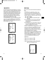
23
If you select ON and press the ENTER button, the MOTION
DET screen will come up. You can set the AREA to which the
Motion Detection function will be applied to either PRESET or
USER. If you set the AREA option to PRESET, the Motion
Detection function will be applied to the areas preset as factory
defaults. If you set the AREA option to USER and press the
ENTER button, you can change the area size and position and
select the area where you want to apply the Motion Detection
function. You can specify the size of the area by using the UP,
DOWN, LEFT, and RIGHT buttons. If the area is not flashing,
press the ENTER button. When the area starts flashing, use the
UP, DOWN, LEFT and RIGHT buttons to specify the location of
the area. Use the ENTER button and the UP, DOWN, LEFT,
and RIGHT buttons to specify the size of the area and to
position the area. Press the ENTER button again to exit the
AREA setting menu. You can use the SENSITIVITY option to
set the motion detection sensitivity. The higher the setting, the
more sensitive the motion detection.
SIZE
LOCATION
CAMERA ID OFF
IRIS ALC...
SHUTTER OFF
AGC LOW
WHITE BAL ATW1
FOCUS MODE AF
MOTION DET ON...
COLOR/BW COLOR
PRIVACY ...
SPECIAL ...
PRESET ...
EXIT QUIT
(MOTION DET)
AREA PRESET...
SENSITIVITY L---I---H
RET
(MOTION DET)
AREA USER...
SENSITIVITY L---I---H
RET
Press the
ENTER
button.
Press the
ENTER
button.
❙
FOCUS MODE
The FOCUS MODE menu performs AF(Auto Focus),
MF(Manual Focus), and ONEAF(One Auto Focus).
✔
AF : Focuses automatically by continuously monitoring the
screen in AUTO FOCUS mode. It does not process the
FOCUS button input because it focuses automatically
during ZOOM.
✔
MF : You can manually adjust the focus.
✔
ONEAF : Focusing will take about 5 seconds in ONEAF
mode. When turned off, it is same to the MF
mode.
CAMERA ID OFF
IRIS ALC...
SHUTTER OFF
AGC LOW
WHITE BAL ATW1
FOCUS MODE AF
MOTION DET OFF
COLOR/BW COLOR
PRIVACY OFF
SPECIAL ...
PRESET ...
EXIT QUIT
❙
MOTION DET
MOTION DET detects any motion. Set up this function
during no human movement to detect break-in. Once
detected, an ALARM signal will be given for 5 seconds. As
MOTION DET detects any motion, so it can set up the
motion detection sensitivity. Select ON... and press [ENTER]
and the MOTION DET submenu screen will appear.
❖
MOTION detection function operates based on the
brightness change within the setup region. Therefore,
erroneous operation may occur depending on the brightness
difference between the background and the object that is
being taken, or the status of the area setup, etc.
00544A_C4207(P)-E+R+P 6/5/06 10:29 AM ˘` 23

26
E
25
✔
AUTO...
Depending on illumination, it is automatically switched to
the COLOR or BW mode. In the poor illumination
environment, turns IR Filter off to convert to the Black-and-
White mode for better sensitivity and in the good
illumination environment, turns it on to convert to the
COLOR mode for worse sensitivity. Select AUTO and press
[Enter] and the AUTO BW submenu will appear to control
the BW level. Depending on ON or OFF, the BURST signal
may output or no. It also sets up the duration for conversion
and the brightness level for the conversion from the COLOR
mode to the BW mode. Duration options are 10Sec.,
30Sec., 1Min., and 5Min.. In the BW mode, the WHITE BAL
menu will be marked --- to make setup unavailable.
(AUTO)
BURST ON
LEVEL MEDIUM
DURATION S ---I--- L
RET
CAMERA ID OFF
IRIS ALC...
SHUTTER OFF
AGC ---
WHITE BAL ATW1
FOCUS MODE AF
MOTION DET OFF
COLOR/BW AUTO...
PRIVACY OFF
SPECIAL ...
PRESET ...
EXIT QUIT
Press the
ENTER
button.
❖ In AUTO mode, AGC will be displayed as “---“. You can’t adjust
the settings manually.
- ALARM ON : It sends out signals through the ALARM output
port in the BW mode.
-
ALARM OFF : The ALARM output port is synchronized with the
MOTION DET finction regardiess of the COLOR/BW mode.
- BURST ON : The color burst signal is output together with
black and white composite video signal.
BURST OFF : The color burst signal is not output.
-
LEVEL : You can set the brightness level that changes from
COLOR mode to BW mode in 3 steps : LOW, MEDIUM, and HIGH.
- DWELL TIME : Set the HOLDING time for switching
between COLOR and BW mode depending the changes in
the amount of light. You can set the HOLDING time to 10sec
(S), 30sec, 60sec, or 300sec( L).
❙
COLOR / BW
COLOR/BW turns IR(Infrared) Filter on or off. In the poor
illumination environment, turns IR Filter off to raise the
sensitivity to the same level as an black-and-white camera while
in the good illumination environment, turns it on to convert to the
COLOR mode in the normal screen condition to lower the
sensitivity.
✔
COLOR
This is the IR Filter ON mode with a normal color screen.
You can press the [Enter] key to set the COLOR GAIN
LEVEL. And when the AGC function is on, you can set the
AGC COLOER LEVEL.
✔
BW...
This is the IR Filter OFF mode, black-and-white (with the
same sensitivity as a black-and-white camera). Select BW...
and press [Enter] and the BW submenu will appear. You
may determine to sent out BURST signals by ON or OFF
setting in this submenu.
❖
WHITE BAL will be marked --- so that setup is unavailable.
(BW)
BURST OFF
RET
CAMERA ID OFF
IRIS ALC...
SHUTTER OFF
AGC LOW
WHITE BAL ---
FOCUS MODE AF
MOTION DET OFF
COLOR/BW BW...
PRIVACY OFF
SPECIAL ...
PRESET ...
EXIT QUIT
Press the
ENTER
button.
Press the
ENTER
button.
CAMERA ID ON...
IRIS ALC...
SHUTTER OFF
AGC LOW
WHITE BAL ATW
FOCUS MODE AF
MOTION DET OFF
COLOR/BW COLOR...
PRIVACY ...
SPECIAL ...
PRESET ...
EXIT QUIT
(COLOR)
GAIN (0)I--------
AGC COLOR (0)----I----
RET
00544A_C4207(P)-E+R+P 6/5/06 10:29 AM ˘` 25

28
E
27
Press the
ENTER
button.
PRIVACY NO. 0
POSITION SET ON...
SIZE …
LOCATION …
EXIT QUIT
❖
The rim of the screen cannot be hidden by the
PRIVACY ZONE area. Please be careful for setup.
❖ It is recommended to deactivate the DIS function in the
no vibration environment.
You shall set up the position of ZOOM/FOCUS in the
PRIVACY ZONE area from the POSITION SET menu. Press
UP/DOWN/LEFT/RIGHT key to size the PRIVACY ZONE
area from the SIZE menu. Press UP/DOWN/LEFT/RIGHT
key to locate the PRIVACY ZONE area from the LOCATION
menu.
✔
EXT...
This menu automatically converts the COLOR Mode into
the BW Mode or vice versa depending on illumination with
an external sensor. If you select the EXIT menu and press
the [Enter] key, the EXTERNAL BW submenu will appear
on the menu screen. You will be able to send out the
BURST signal by turning on or off in this menu.
Press the
ENTER
button.
(EXTERNAL BW)
BURST ON
RET
CAMERA ID OFF
IRIS ALC...
SHUTTER OFF
AGC LOW
WHITE BAL ATW1
FOCUS MODE AF
MOTION DET OFF
COLOR/BW EXT...
PRIVACY OFF
SPECIAL ...
PRESET ...
EXIT QUIT
Press the
ENTER
button.
(PRIVACY MAP)
0 1 2 3
4 5 6 7
RET
CAMERA ID OFF
IRIS ALC…
SHUTTER OFF
AGC ---
WHITE BAL ATW1
FOCUS MODE AF
MOTION DET OFF
COLOR/BW AUTO…
PRIVACY OFF
SPECIAL …
PRESET …
EXIT QUIT
❙
PRIVACY
This function designates an area that may violate PRIVACY
and hides it when the camera shoots a screen including the
area to protect Privacy. Up to 8 PRIVACY ZONEs are
available for setup. After PRIVACY menu setup, press
ENTER to enter the PRIVACY MAP screen. Now, press
UP/DOWN/LEFT/RIGHT key to choose one out of PRIVACY
0~7 and press ENTER to enter the PRIVACY setup menu.
❙
SPECIAL
In SPECIAL menu, you can set the settings related to the
VIDEO signals and various additional functions.
CAMERA ID OFF
IRIS ALC...
SHUTTER OFF
AGC LOW
WHITE BAL ATW
FOCUS MODE AF
MOTION DET OFF
COLOR/BW COLOR...
PRIVACY ...
SPECIAL ...
PRESET ...
EXIT QUIT
Press the
ENTER
button.
(SPECIAL)
POSI/NEGA +
DIS OFF
REVERSE OFF
DETAIL (0)--I-
Y-LEVEL (0)I--------
C-LEVEL (0)I--------
OTHER SET ...
RET
- POSI/NEGA : Output as it is or mirror the video brightness signal.
- DIS : Digital Image Stabilization. Compensates hand shivering
errors.
- REVERSE : Mirrors video signals horizontally, vertically, or both.
- DETAIL : Controls the horizontal or vertical distinction.
- Y-LEVEL : It is used to set the levels for the Sync signal and the
entire brightness signal of the video signal.
00544A_C4207(P)-E+R+P 6/5/06 10:29 AM ˘` 27

30
E
29
- C-LEVEL: It is used to set the levels for the Burst signal
and the entire colour signal of the video signal.
- OTHER SET
In OTHER SET menu, you can adjust LANGUAGE, CTRL
TYPE, ZOOM SPEED, D-ZOON, RS-485, SYSTEM
INFO..., and V-SYNC function, DISPLAY ZOOM etc. When
you press [ENTER] key from OTHER SET menu, the
OTHER SET additional menu screen appear.
- LANGUAGE : Selects English/Russian/Polish OSD menu.
- CTRL TYPE : By inputting the wire remote port, you may
set up the mode, A, B, C, or D.
- ZOOM SPEED : Use [Left, Right] key in the ZOOM SPEED
menu to set the speed as follows.
- ZOOM SPEED 1 : About 17Sec. from X 1 to X 32(Slowest)
- ZOOM SPEED 2 : About 10Sec. from X 1 to X 32(Slow)
- ZOOM SPEED 3 : About 6Sec. from X 1 to X 32(Fast)
- ZOOM SPEED 4 : About 3Sec. from X 1 to X 32(Fastest)
- D-ZOOM : Sets up the Digital Zoom magnification ratio up
to x10.
- RS-485 : Sets up RS-485 Communication Protocol,
Address, and Baud Rate.
Code
A
B
C
D
Tele
-6V
-6V
+6V
+6V
Wide
+6V
+6V
-6V
-6V
Far
+6V
-6V
+6V
-6V
Near
-6V
+6V
-6V
+6V
❖
V-SYNC menu is only available in SCC-C4307.
❖
When a DC power is supplied, V-SYNC menu will be displayed
as --- and you cannot make any settings.
(OTHER SET)
LANGUAGE ENGLISH
CTRL TYPE A
ZOOM SPEED 4
D-ZOOM OFF
RS-485 ...
SYSTEM INFO ...
V-SYNC INT
DISPLAY ZOOM OFF
RET
(SPECIAL)
POSI/NEGA +
DIS OFF
REVERSE OFF
DETAIL (0)--I-
Y-LEVEL (0)I--------
C-LEVEL (0)I--------
OTHER SET ...
RET
- SYSTEM INFO : You can confirm settings related to the
RS-485 communication, product serial number, and the
software version.
- V-SYNC : INT shall be selected to use internal
synchronization. LINE... is used to synchronize several
camera phases for the multi camera operation by using an
external signal(AC signal). As there may be a slight deviation
between sets, adjusts PHASE to overcome this handicap.
When you use AC power source, V-SYNC is available.
Select LINE... and press [ENTER] and the PHASE control
submenu will appear. The PHASE control ranges from -106H
to +106H as for NTSC and from -138H to +138H as for PAL.
Press the
ENTER
button.
(OTHER SET)
LANGUAGE ENGLISH
CTRL TYPE A
ZOOM SPEED 4
D-ZOOM OFF
RS-485 ...
SYSTEM INFO ...
V-STNC INT
RET
(RS-485)
PROTOCOL SAMSUNG
BAUD RATE 9600
ADDRESS 0
RET
Press the
ENTER
button.
(OTHER SET)
LANGUAGE ENGLISH
CTRL TYPE A
ZOOM SPEED 4
D-ZOOM OFF
RS-485 ...
SYSTEM INFO ...
V-STNC INT
RET
Press the
ENTER
button.
(SPECIAL)
CTRL TYPE A
POSI/NEGA +
ZOOM SPEED 1
DIS OFF
D-ZOOM OFF
REVERSE OFF
RS-485 ...
V-SYNC LINE...
LANGUAGE ENGLISH
DETAIL (0)--I-
RET
(LINE LOCK)
PHASE (000)----I----
RET
(SYSTEM INFO)
ROM VER 1.000
EEP VER 1.000
PROTOCOL SAMSUNG
ADDRESS 0
TYPE RS-485, HALF
BAUD RATE 9600
SERIAL NO 000000000000000
RET
00544A_C4207(P)-E+R+P 6/5/06 10:29 AM ˘` 29

32
E
31
CAMERA ID OFF
IRIS ALC...
SHUTTER OFF
AGC LOW
WHITE BAL ATW1
FOCUS MODE AF
MOTION DET OFF
COLOR/BW COLOR
PRIVACY OFF
SPECIAL ...
PRESET ...
EXIT QUIT
❙
EXIT
The EXIT menu is used to terminate the CAMERA SETUP
menu.
✔
QUIT : Select to ignore any changes you have made and
restore the previously saved settings.
✔
SAVE : Select to save the settings that have been
changed so far.
✔
PRESET : Ignores any change and returns to the default of
the CAMERA menu as set for the product delivery.
❖ HOME RETURN automatically returns to the HOME
position should there is no key input for a certain time.
The HOME position is set to PRESET 0 if it is saved or
Off if not.
HOME RETURN Time Setup
OFF ➞ 1MIN ➞ 2MIN ➞ 3~60MIN ➞ 2 HOUR ➞ 3~12 HOUR
➞
PRESET NO. 0
POSITION SET ...
PRESET ID OFF
EXIT QUIT
(PRESET MAP)
0 H 1 2 3 4
56789
10 11 12 13 14
15 16 17 18 19
20 21 22 23 24
25 26 27 28 29
30 31 RET
HOME RETURN OFF
EXIT QUIT
❙
PRESET
Select the PRESET menu and press [ENTER] and the
PRESET MAP submenu screen will appear.
Select the PRESET number and press [ENTER] and the
above screen will appear.
✔
POSITION SET :
Memorizes the position of ZOOM or
FOCUS.
✔
PRESET ID :
Designates the ID on the basis of the
PRESET position as the CAMERA ID.
Press the
ENTER
button.
❈ If no change on the ZOOM scale is made for 3 seconds, the
information window will disappear.
❙
DISPLAY ZOOM
In DISPLAY ZOOM, you can display the ZOOM scale on the screen.
Press the
ENTER
button.
(OTHER SET)
LANGUAGE ENGLISH
CTRL TYPE A
ZOOM SPEED 4
DIGITAL ZOOM X10
RS-485 ...
SYSTEM INFO ...
V-SYNC LINE...
DISPLAY ZOOM ON
EXIT
10X
00544A_C4207(P)-E+R+P 6/5/06 10:29 AM ˘` 31

34
E
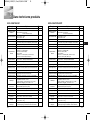
33
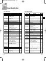
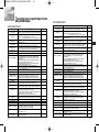
SCC-C4207P/C4307P
Product Type
Power Supply
Voltage
Power Consumption
Broadcast System
Imaging Device
Effective Pixe
Scanning Method
Line Frequency
Synchronization
Method
Resolution
S/N Ratio
Minimum Scene
Illumination
Dynamic Range
Color Temp.
Signal Output
Lens
Remote Control
Alarm
Operating Temp.
Operating Humidity
Dimensions
Weight
Lens Lifetime
Zoom Lens Built-in WDR Color Camera(PAL TYPE)
- SCC-C4207P : DC 12V
±
10%
- SCC-C4307P
: DC 12V±10%
AC 24V±10% (50Hz±0.3Hz)
- SCC-C4207P : 5.5W
- SCC-C4307P : 6W
- PAL Standard Color System
- 1/4 inch WDR compatible Exview HAD CCD
- 752(H) x 582(V)
- 625 Line, 2:1 Interlace
- SCC-C4207P
Horizontal : 15,625 Hz (INT)
Vertical : 50 Hz (INT)
- SCC-C4307P
Horizontal : 15,625 Hz(INT), 15,625 Hz(L/L)
Vertical : 50 Hz(INT), 50 Hz(L/L)
-SCC-C4207P : Internal Only
-SCC-C4307P : Internal/Line-Lock
- 480 TV Lines
- 50dB(AGC OFF)
- Color :
0.18 Lux (SENS UP X4) 0.005 Lux (SENS UP X160)
-
B/W :
0.018 Lux (SENS UP X4) 0.0005 Lux (SENS UP X160)
- Max 128
- ATW1/ATW2/AWC/Manual MODE
(3200K, 5600K, R/B Gain Adjustment)
- Composite Video Out : 1.0 Vp-p 75ohms/BNC
-
32x Zoom Lens in a single unit
- Focal length : 3.55 to 113 mm
- Aperture : F1.69(Wide), F4.17(Tele)
- MOD(Minimum Object Distance) : 2.5m
- Tele/Wide(ZOOM), Near/Far(FOCUS),
Iris Open/Close
- Alarm Output: 1 Out (Motion Detection)
-10°C ~ +50°C
- ~90%
- SCC-C4207 : 59.5 X 60.5 X 115.7 mm
- SCC-C4307 : 59.5 X 60.5 X 149.9 mm
- SCC-C4207 : 390g
- SCC-C4307 : 515g
- About 1 year (when using the Full-AF mode)
Item Description
Remark
5
Product Specification
SCC-C4207/C4307
Product Type
Power Supply
Voltage
Power Consumption
Broadcast System
Imaging Device
Effective Pixe
Scanning Method
Line Frequency
Synchronization
Method
Resolution
S/N Ratio
Minimum Scene
Illumination
Dynamic Range
Color Temp.
Signal Output
Lens
Remote Control
Alarm
Operating Temp.
Operating Humidity
Dimensions
Weight
Lens Lifetime
Zoom Lens Built-in WDR Color Camera(NTSC TYPE)
- SCC-C4207 : DC 12V±10%
- SCC-C4307
: DC 12V±10%
AC 24V±10% (60Hz±0.3Hz)
- SCC-C4207 : 5.5W
- SCC-C4307 : 6W
- NTSC Standard Color System
- 1/4 inch WDR compatible Exview HAD CCD
- 768(H) x 494(V)
- 525 Line, 2:1 Interlace
- SCC-C4207
Horizontal : 15,734 Hz (INT)
Vertical : 59.94 Hz (INT)
- SCC-C4307
Horizontal : 15,734 Hz(INT), 15,750 Hz(L/L)
Vertical : 59.94 Hz(INT), 60 Hz(L/L)
-SCC-C4207 : Internal Only
-SCC-C4307 : Internal/Line-Lock
- 480 TV Lines
- 50dB(AGC OFF)
- Color :
0.18 Lux (SENS UP X4) 0.005 Lux (SENS UP X160)
-
B/W :
0.018 Lux (SENS UP X4) 0.0005 Lux (SENS UP X160)
- Max 128
- ATW1/ATW2/AWC/Manual MODE
(3200K, 5600K, R/B Gain Adjustment)
- Composite Video Out : 1.0 Vp-p 75ohms/BNC
-
32x Zoom Lens in a single unit
- Focal length : 3.55 to 113 mm
- Aperture : F1.69(Wide), F4.17(Tele)
- MOD(Minimum Object Distance) : 2.5m
- Tele/Wide(ZOOM), Near/Far(FOCUS),
Iris Open/Close
- Alarm Output: 1 Out (Motion Detection)
-10°C ~ +50°C
- ~90%
- SCC-C4207 : 59.5 X 60.5 X 115.7 mm
- SCC-C4307 : 59.5 X 60.5 X 149.9 mm
- SCC-C4207 : 390g
- SCC-C4307 : 515g
- About 1 year (when using the Full-AF mode)
Item Description
Remark
00544A_C4207(P)-E+R+P 6/5/06 10:29 AM ˘` 33

E
Memo
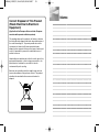
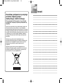
Correct Disposal of This Product
(Waste Electrical & Electronic
Equipment)
(Applicable in the European Union and other European
countries with separate collection systems)
This marking shown on the product or its literature, indicates
that it should not be disposed with other household wastes at
the end of its working life. To prevent possible harm to the
environment or human health from uncontrolled waste
disposal, please separate this from other types of wastes and
recycle it responsibly to promote the sustainable reuse of
material resources.
Household users should contact either the retailer where they
purchased this product, or their local government office, for
details of where and how they can take this item for
environmentally safe recycling.
Business users should contact their supplier and check the
terms and conditions of the purchase contract. This product
should not be mixed with other commercial wastes for
disposal.
00544A_C4207(P)-E+R+P 6/5/06 10:29 AM ˘` 35

Ru
✽
ÑÎfl Ó·ÂÒÔ˜ÂÌËfl Ô‡‚ËθÌÓÈ ˝ÍÒÔÎÛ‡Ú‡ˆËË ‰‡ÌÌÓ„Ó ËÁ‰ÂÎËfl
Ó·flÁ‡ÚÂθÌÓ ÔÓ˜ÚËÚ Ô˂‰ÂÌÌ˚ ‚ ˝ÚÓÏ ÛÍÓ‚Ó‰ÒÚ‚Â
“臂Ë· ÚÂıÌËÍË ·ÂÁÓÔ‡ÒÌÓÒÚË”.
ÇàÑÖéäÄåÖêÄ ë ìÇÖãàóÖçàÖå
320ï à Åéãúòàå
ÑàçÄåàóÖëäàå ÑàÄèÄáéçéå
SCC-C4207(P)/C4307(P)
êÛÍÓ‚Ó‰ÒÚ‚Ó
ÔÓθÁÓ‚‡ÚÂÎfl
00545A_C4207(P)-Ru 6/5/06 10:35 AM ˘` a
Strona się ładuje...
Strona się ładuje...
Strona się ładuje...
Strona się ładuje...
Strona się ładuje...
Strona się ładuje...
Strona się ładuje...
Strona się ładuje...
Strona się ładuje...
Strona się ładuje...
Strona się ładuje...
Strona się ładuje...
Strona się ładuje...
Strona się ładuje...
Strona się ładuje...
Strona się ładuje...
Strona się ładuje...
Strona się ładuje...
Strona się ładuje...
Strona się ładuje...
Strona się ładuje...
Strona się ładuje...
Strona się ładuje...
Strona się ładuje...
Strona się ładuje...
Strona się ładuje...
Strona się ładuje...
Strona się ładuje...
Strona się ładuje...
Strona się ładuje...
Strona się ładuje...
Strona się ładuje...
Strona się ładuje...
Strona się ładuje...
Strona się ładuje...
-
 1
1
-
 2
2
-
 3
3
-
 4
4
-
 5
5
-
 6
6
-
 7
7
-
 8
8
-
 9
9
-
 10
10
-
 11
11
-
 12
12
-
 13
13
-
 14
14
-
 15
15
-
 16
16
-
 17
17
-
 18
18
-
 19
19
-
 20
20
-
 21
21
-
 22
22
-
 23
23
-
 24
24
-
 25
25
-
 26
26
-
 27
27
-
 28
28
-
 29
29
-
 30
30
-
 31
31
-
 32
32
-
 33
33
-
 34
34
-
 35
35
-
 36
36
-
 37
37
-
 38
38
-
 39
39
-
 40
40
-
 41
41
-
 42
42
-
 43
43
-
 44
44
-
 45
45
-
 46
46
-
 47
47
-
 48
48
-
 49
49
-
 50
50
-
 51
51
-
 52
52
-
 53
53
-
 54
54
-
 55
55


Samsung SCC-C4207P Instrukcja obsługi
- Kategoria
- Kamery ochrony
- Typ
- Instrukcja obsługi
- Niniejsza instrukcja jest również odpowiednia dla
w innych językach
- italiano: Samsung SCC-C4207P Manuale utente
Powiązane artykuły
-
Samsung SCC-C6407P Instrukcja obsługi
-
-
-
-
Samsung SCC-C7435 Instrukcja obsługi
-
-
-
-
-
Samsung SCC-A2013P Instrukcja obsługi