Novus NVIP-4SD-6540/25/F Instrukcja obsługi
- Kategoria
- Kamery ochrony
- Typ
- Instrukcja obsługi

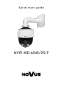
Quick start guide
NVIP-4SD-6540/25/F

NVIP-4SD-6540/25/F Quick start guide version 1.0
All rights reserved © AAT SYSTEMY BEZPIECZEŃSTWA Sp. z o.o.
2
THE PRODUCT MEETS THE REQUIREMENTS CONTAINED IN THE FOLLOWING DIRECTIVES:
Information
The device, as a part of professional CCTV system used for surveillance and control, is not designed
for self installation in households by individuals without technical knowledge.
Excluding of responsibility in case of damaging data on a disk or other devices:
The manufacturer does not bear any responsibility in case of damaging or losing data on a disk or other
devices during device operation.
WARNING!
PRIOR TO UNDERTAKING ANY ACTION THAT IS NOT DESCRIBED FOR THE GIVEN
PRODUCT IN USER’S MANUAL AND OTHER DOCUMENTS DELIVERED WITH THE
PRODUCT, OR IF IT DOES NOT ARISE FROM THE USUAL APPLICATION OF THE
PRODUCT, MANUFACTURER MUST BE CONTACTED UNDER THE RIGOR OF EXCLUDING
THE MANUFACTURER’S RESPONSIBILITY FOR THE RESULTS OF SUCH AN ACTION.
IMPORTANT SAFEGUARDS AND WARNINGS
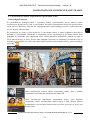
Pictures in this publication showing camera views can be simulations. Actual camera
images may vary depending on the type, model, settings, observation area, or
environmental conditions.
DIRECTIVE 2014/30/EU OF THE EUROPEAN PARLIAMENT AND OF THE
COUNCIL of 26 February 2014 on the harmonization of the laws of the Member States
relating to electromagnetic compatibility (OJ L 96, 29.3.2014, p. 79–106, with changes)
DIRECTIVE 2012/19/EU OF THE EUROPEAN PARLIAMENT AND OF THE
COUNCIL of 4 July 2012 on waste electrical and electronic equipment (WEEE)
(OJ L 197, 24.7.2012, p. 38–71, with changes)
DIRECTIVE 2011/65/EU OF THE EUROPEAN PARLIAMENT AND OF THE
COUNCIL of 8 June 2011 on the restriction of the use of certain hazardous substances in
electrical and electronic equipment (OJ L 174, 1.7.2011, p. 88–110, with changes)
DIRECTIVE 2014/35/EU OF THE EUROPEAN PARLIAMENT AND OF THE
COUNCIL of 26 February 2014 on the harmonization of the laws of the Member States
relating to the making available on the market of electrical equipment designed for use
within certain voltage limits.

NVIP-4SD-6540/25/F Quick start guide version 1.0
All rights reserved © AAT SYSTEMY BEZPIECZEŃSTWA Sp. z o.o.
3
WARNING!
THE KNOWLEDGE OF THIS MANUAL IS AN INDESPENSIBLE CONDITION OF A PROPER
DEVICE OPERATION. YOU ARE KINDLY REQUSTED TO FAMILIRIZE YOURSELF WITH
THE MANUAL PRIOR TO INSTALLATION AND FURTHER DEVICE OPERATION.
WARNING!
USER IS NOT ALLOWED TO DISASSEMBLE THE CASING AS THERE ARE NO USER
-SERVICEABLE PARTS INSIDE THIS UNIT. ONLY AUTHORIZED SERVICE PERSONNEL
MAY OPEN THE UNIT
INSTALLATION AND SERVICING SHOULD ONLY BE DONE BY QUALIFIED SERVICE
PERSONNEL AND SHOULD CONFORM TO ALL LOCAL REGULATIONS
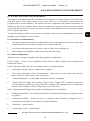
1. Prior to undertaking any action please consult the following manual and read all the safety and
operating instructions before starting the device.
2. Please keep this manual for the lifespan of the device in case referring to the contents of this manual
is necessary;
3. All the safety precautions referred to in this manual should be strictly followed, as they have a direct
influence on user’s safety and durability and reliability of the device;
4. All actions conducted by the servicemen and users must be accomplished in accordance with the
user’s manual;
5. The device should be disconnected from power sources during maintenance procedures;
6. Usage of additional devices and components neither provided nor recommended by the producer is
forbidden;
7. You are not allowed to use the camera in high humidity environment (i.e. close to swimming pools,
bath tubs, damp basements);
8. Mounting the device in places where proper ventilation cannot be provided (e. g. closed lockers etc.)
is not recommended since it may lead to heat build-up and damaging the device itself as a
consequence;
9. Mounting the camera on unstable surface or using not recommended mounts is forbidden.
Improperly mounted camera may cause a fatal accident or may be seriously damaged itself. The
camera must be mounted by qualified personnel with proper authorization, in accordance with this
user’s manual.
10. Device should be supplied only from a power sources whose parameters are in accordance with
those specified by the producer in the camera technical datasheet. Therefore, it is forbidden to
supply the camera from a power sources with unknown parameters, unstable or not meeting
producer’s requirements;
Due to the product being constantly enhanced and optimized, certain parameters and functions
described in the manual in question may change without further notice.
We strongly suggest visiting the www.novuscctv.com/en website in order to access the newest full
manual
IMPORTANT SAFEGUARDS AND WARNINGS

NVIP-4SD-6540/25/F Quick start guide version 1.0
All rights reserved © AAT SYSTEMY BEZPIECZEŃSTWA Sp. z o.o.
4
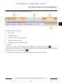
TABLE OF CONTENTS
1. FOREWORD INFORMATION ................................................................................... ..5
1.1. General characteristics ......................................................................................... 5
1.2. Technical specification .................................................................................... ...6
1.3. Camera dimension ........................................................................................... ...8
1.4. Package contents ............................................................................................... ...8
2. START-UP AND INITIAL CONFIGURATION ......................................................... 9
2.1. Description of connectors .................................................................................... 9
2.2. Connecting ethernet cable ................................................................................... 9
2.3. Description of the camera components ............................................................. 10
2.4. Power supply connection .................................................................................. 10
2.5. Wall mounting of the camera. ........................................................................... 11
2.6. Starting the camera ............................................................................................ 12
2.7. Initial configuration via the web browser .......................................................... 13
2.8. Security recommendations for network architecture and configuration ........... 14
3. NETWORK CONNECTION UTILIZING WEB BROSWER ................................ 15
3.1. Recommended PC specification for web browser connections ......................... 15
3.2. Connection with camera via web browser ......................................................... 15
4. WEB INTERFACE - WORKING WITH THE CAMERA ....................................... 17
4.1. The remote preview interface. ............................................................................ 17
5. SD CARD INSTALLATION ....................................................................................... 20
6. RESTORING FACTORY DEFAULTS ..................................................................... 21
6.1. Software factory reset ......................................................................................... 21
6.2. Software factory reset using the NMSiptool ...................................................... 21
6.3. Hardware factory reset ...................................................................................... 21
7. SPECIAL PRESETS ..................................................................................................... 22
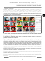
8. FACE RECOGNITION AND COMPARISON ......................................................... 23
8.1. Installation recommendations ............................................................................. 23
8.2. Camera configuration ......................................................................................... 23
8.3. View the results of face recognition and comparison ....................................... 27
8.4. Saving of recognized faces on a memory card - search for recordings ............. 30
9. CONFIGURATION OF OBJECT TRACKING OPTIONS .................................... 34
TABLE OF CONTENTS

NVIP-4SD-6540/25/F Quick start guide version 1.0
All rights reserved © AAT SYSTEMY BEZPIECZEŃSTWA Sp. z o.o.
5
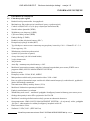
1. FOREWORD INFORMATION
1.1. General Characteristics
• Sensor resolution: 4 megapixels
• Mechanical IR cut filter, IR operation capability
• Min. Illumination from 0,002 lx/F1.65 (0 lx with IR LED on)
• Wide Dynamic Range (WDR) for enhanced image quality in diverse light conditions
• Digital Slow Shutter (DSS)
• Digital Noise Reduction (DNR)
• Defog Function (F-DNR)
• Highlight Compensation (HLC)
• Back Light Compensation (BLC)
• Lens type: motorzoom with AF and AI, f=4.8 ~ 120mm/F1.65 ~ 3.8
• Optical zoom: 25x
• Built-in IR LED illuminator
• 8 cruises (16 presets per cruise)
• 4 traces (up to 180 seconds each)
• 2 scan modes
• 360 presets
• Auto-flip - automatic camera rotation 180°
• The ability to control zoom, tilt and pan directly via the website and from the NMS program
(NOVUS MANAGEMENT SYSTEM)
• Motion detection
• Compression: H.264, H.265, MJPEG
• Max video processing resolution: 2560 x 1440
• Operation in 3-stream mode: ability to define compression, resolution, speed and quality for each
stream
• Advanced Video Content Analysis (VCA)
• The ability to track recognized objects
• Pre & post-alarm functions
• Built-in web server - the ability to view and configure camera settings via the website
• Support for micro SD memory cards up to 256 GB
• Possibility to broadly define the system's reaction to alarm events
• NMS (Novus Management System) software - for video recording, live viewing, playback and
remote configuration of IP video devices
• Degree of protection IP66
• Power supply: 12VDC, PoE+ (IEEE 802.3at)
FOREWORD INFORMATION

NVIP-4SD-6540/25/F Quick start guide version 1.0
All rights reserved © AAT SYSTEMY BEZPIECZEŃSTWA Sp. z o.o.
6
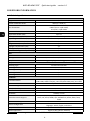
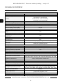
1.2. Technical specification
FOREWORD INFORMATION
IMAGE
Image Sensor 4 MPX CMOS sensor 1/2.5” ON Semiconductor
Number of Eecve Pixels 2592 (H) x 1944 (V)
Min. Illuminaon
0.01 lx/F1.65 - color mode,
0.002 lx/F1.65 - B/W mode,
0 lx (IR on) - B/W mode
Electronic Shuer auto: 1 s ~ 1/100000 s
Digital Slow Shuer (DSS) up to 1 s
Wide Dynamic Range (WDR) yes (double scan sensor), 120dB
Digital Image Stabilizaon (DIS) yes
Digital Noise Reducon (DNR) 2D, 3D
Defog Funcon (F-DNR) yes
Highlight Compensaon (HLC) yes
Back Light Compensaon (BLC) yes
Reducon of image icker (Anicker) yes
LENS
Opcal Zoom 25x
Lens Type motorized, auto-iris funcon, f=4.8 ~ 120 mm/F1.65 ~ F3.8
Auto-focus zoom trigger, day/night mode trigger, manual trigger
DAY/NIGHT
Switching Type mechanical IR cut lter
Switching Mode auto, manual, me
Switching Level Adjustment yes
Switching Schedule yes
Visible Light Sensor yes
NETWORK
Stream Resoluon
2560 x 1440 (QHD), 2048 x 1536 (QXGA), 1920 x 1080 (Full HD),
1280 x 960, 1280 x 720 (HD), 704 x 576, 640 x 480 (VGA), 352 x 288
Frame Rate 30 fps for each resoluon
Mulstreaming Mode 3 streams
Video/Audio Compression H.264, H.265, MJPEG/-
Number of Simultaneous Connecons max. 10
Bandwidth 50 Mb/s in total
Network Protocols Support
HTTP, TCP/IP, IPv4/v6, UDP, HTTPS, FTP, DHCP, DNS, DDNS, NTP,
RTSP, RTP, UPnP, SNMP, QoS, IEEE 802.1X, PPPoE, SMTP, RTCP,
ICMP
ONVIF Protocol Support Prole S
Camera Conguraon
from Internet Explorer browser
languages: Polish, English, and others
Compable Soware NMS, NVR-6000 Viewer, N Control 6000
Mobile applicaons SuperLive Plus (iPhone, Android)

NVIP-4SD-6540/25/F Quick start guide version 1.0
All rights reserved © AAT SYSTEMY BEZPIECZEŃSTWA Sp. z o.o.
7
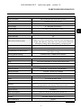
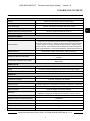
FOREWORD INFORMATION
PTZ
Preset Commands 360 including 20 special (funcon) presets
Tours 8 (up to 16 presets per tour)
Paerns 4 (max. 360 commands or 180 s for each paern)
Tilt/Pan Range -5° ~ 90°/360° (connuous)
Pan/Tilt Speed up to 80°/s (proporonal to zoom)
Preset Speed up to 80°/s
OTHER FUNCTIONS
Moon Detecon yes
Video Content Analysis (VCA)
Auto Tracking linked to Video Content Analysis (VCA) funcons,
tamper, line cross, zone entrance, zone exit, cross counng, Scene
Change, Video Blurred, Video Color Cast, zone entrance detecon
and object tracking, objects disnguishing, comparing faces
Image Processing 180˚ image rotaon, sharpening, mirror eect
Prealarm/Postalarm up to 6 s/up to 120 s
System Reacon to Alarm Events
e-mail with aachment, saving le on FTP server, saving le on SD
card, object tracking
Restoring default sengs via web browser, via NMS IPTool soware
IR LED
LED Number 6
Range up to 130 m (depends on current opcal zoom value)
Smart IR yes (hardware support)
INTERFACES
Network Interface 1 x Ethernet - RJ-45 interface, 10/100 Mbit/s
Memory Card Slot microSD - capacity up to 256GB
INSTALLATION PARAMETERS
Dimensions (mm) 173 (Ф) x 268 (H) with bracket: 173 (W) x 342 (H) x 300 (L)
Weight 2.1 kg with bracket: 2.8 kg
Degree of Protecon IP 66 (details in the user’s manual)
Enclosure
aluminium, white, IK10 impact rang, in set: outdoor housing
(integrated with the camera), wall mount bracket
Power Supply PoE+, 12 VDC (100 ~ 230 VAC/12 VDC PSU in-set included)
Surge protecon TVS 4000 V
Power Consumpon 6 W, 15.5 W (IR on), 20 W (IR and heater on)
Operang Temperature -30°C ~ 55°C
Humidity max. 90%, relave (non-condensing)
Built-in Heater/Fan yes/yes

NVIP-4SD-6540/25/F Quick start guide version 1.0
All rights reserved © AAT SYSTEMY BEZPIECZEŃSTWA Sp. z o.o.
8
FOREWORD INFORMATION
1.3. Camera dimensions
1.4. Package contents
After you open the package make sure that the following elements are inside:
• IP camera
• Wall mount
• AC adapter
• Accessories bag
• Quick start guide
If any of this elements has been damaged during transport, pack all the elements back into the original
box and contact your supplier for further assistance.
Before starting the device familiarize yourself with the description and the role of particular
inputs, outputs and adjusting elements that the device is equipped with.
Caution!
If the device was brought from a location with lower temperature, please wait until it reaches the
temperature of location it is currently in. Turning the device on immediately after bringing it from a
location with lower ambient temperature is forbidden, as the condensing water vapour may cause
short-circuits and damage the device as a result.

NVIP-4SD-6540/25/F Quick start guide version 1.0
All rights reserved © AAT SYSTEMY BEZPIECZEŃSTWA Sp. z o.o.
9
START-UP AND INITIAL CONFIGURATION
2.START-UP AND INITIAL CONFIGURATION
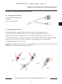
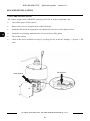
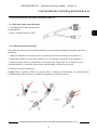
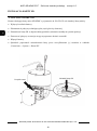
2.2. Connecting ethernet cable
To maintain tightness of ethernet cable connection, please follow instruction below:
1. Unscrew the nut (b) from the connector cover (a), put the sealing ring on the socket (c)
2. Route the network cable through parts (a) and (b). Insert the RJ-45 plug into the socket (c)
3. Screw the connector cover (a) onto the socket (c). Press the cable seal (d) into the upper part of the
connector cover (a) as far as it will go - the seal has a cut enabling it to be put on the cable.
4. Tighten the nut (b) as far as it will go.
Warning! The 12VDC power connector, the audio and alarm I/O connectors are not hermetic. The user
should ensure the tightness of these sockets on his own.
b a
b
a
c
d
1
2
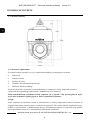
2.1. Description of connectors
1. 100 Mb/s Ethernet port (RJ-45
connector)
2. Power supply 12VDC

NVIP-4SD-6540/25/F Quick start guide version 1.0
All rights reserved © AAT SYSTEMY BEZPIECZEŃSTWA Sp. z o.o.
10
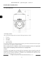
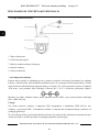
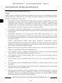
2.3. Description of the camera components
1. Electrical connectors
2. Safety cable
3. Place of installation of the wall bracket
4. Camera housing
5. PTZ dome
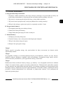
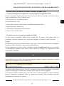
2.4. Power supply connection
The camera should be powered from the included AC adapter. It is allowed to power the camera from
other sources, provided that they meet the technical requirements of the camera. The source must
provide stabilized 12VDC voltage, must allow the consumption of at least 25W of power, and have a
cylindrical DC 2.1 / 5.5 plug with the correct polarity of the contacts:
It is also possible to power the camera via the RJ45 network socket, using PoE + technology (IEEE
802.3at).
Caution!
Do not use power supplies and POE adapters that do not comply with the IEEE 802.3at standard, the so
-called "passive POE" power supplies. Damage resulting from the use of an unsuitable adapter is not
covered by the warranty!
In order to provide protection against voltage surges/lightning strikes, usage of appropriate surge
protectors is advised. Any damages resulting from surges are not eligible for service repairs.
START-UP AND INITIAL CONFIGURATION
1
4
2
3
5

NVIP-4SD-6540/25/F Quick start guide version 1.0
All rights reserved © AAT SYSTEMY BEZPIECZEŃSTWA Sp. z o.o.
11
2.5. Wall mounting of the camera
A. Preparation of the installation site:
1. Place the mounting template (or the foot of the wall mount) on the surface on which the camera
is to be mounted and use it as a template to mark the drilling points.
2. Drill holes in the marked places, insert expansion plugs.
3. Drill a hole for the cables at the connection point (if necessary)
4. Screw the two screws into the upper holes until they protrude by about 12 mm
B. Preparing the camera:
1. Pass the cables through the wall bracket
2. Attach the bracket to the camera.
3. Fasten the safety cable to the ear in the holder.
C. Camera Installation:
1. Connect the electric wires
2. Hang the camera with the bracket on the two upper screws
3. Screw in the two lower screws until they stop
4. Tighten the top screws fully
Caution!
Pay particular attention to the surface to which is attached the camera to have the appropriate capacity.
Caution!
In the case of installation on uneven / rough surfaces, it is recommended to additionally seal the place
of mounting the camera foot with sealing compound. Pay particular attention to the mounting holes
and if they are through, they should also be sealed.
Caution!
The declared tightness class of the camera applies to its housing and does not take into account the
possibility of moisture penetrating the camera through the connection cables. Securing the cables by
e.g. sealing them with an appropriate mass or hiding them in a sealed container is the responsibility of
the person installing the camera. The manufacturer is not responsible for any damage or damage to the
camera caused by failure to fulfill the above-mentioned obligation, which at the same time means that
they are not subject to warranty repairs.
START-UP AND INITIAL CONFIGURATION

NVIP-4SD-6540/25/F Quick start guide version 1.0
All rights reserved © AAT SYSTEMY BEZPIECZEŃSTWA Sp. z o.o.
12
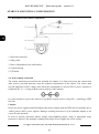
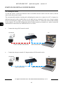
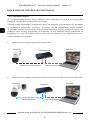
2.6. Starting the camera
To start the camera, connect the Ethernet cable to the RJ45 network socket of the IP camera, and the
other end to the network switch.
The recommended method of starting and configuring the camera is to connect it to a PC or laptop in a
dedicated network switch to which there are no other devices connected. In the case of power supply
from an external power supply, you can use any network switch, or connect the network cable directly
to the computer. For network configuration data (IP address, gateway, netmask etc.), please contact the
administrator of the network in which the device is to work.
• Connection using a PoE network switch
• Connection using an external AC adapter and non-PoE network switch
START-UP AND INITIAL CONFIGURATION
PC IP camera
Power and data transmission Data transmission
PoE switch
IP camera
Data transmission Data transmission
Switch
PC

NVIP-4SD-6540/25/F Quick start guide version 1.0
All rights reserved © AAT SYSTEMY BEZPIECZEŃSTWA Sp. z o.o.
13
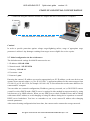
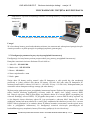
• Connection using the camera's external AC adapter and direct connection to a computer
Caution!
In order to provide protection against voltage surges/lightning strikes, usage of appropriate surge
protectors is advised. Any damages resulting from surges are not eligible for service repairs.
2.7. Initial configuration via the web browser
The default network settings for 6000 IP camera series are :
1. IP address= 192.168.1.200
2. Network mask - 255.255.255.0
3. Gateway - 192.168.1.1
4. User name - root
5. Password - pass
Knowing the camera’s IP address you need to appropriately set PC IP address, so the two devices can
operate in one network subnet ( e.g. for IP 192.168.1.1, appropriate address for the camera ranges from
192.168.1.2 to 192.168.1.254, for example 192.168.1.60). It is not allowed to set the same addresses for
camera and PC computer
You can either set a network configuration (IP address, gateway, net mask, etc.) of NOVUS IP camera
yourself or select DHCP mode (DHCP server is required in this method in target network) by using
web browser or by NMS software. When you use DHCP server check IP address lease and its linking
with camera MAC address to avoid changing or losing IP address during device operation or network/
DHCP server breakdown. You have to remember to use a new camera IP address after changing
network parameters.
After network setting configuration has been done, the camera can be connected to a target network.
START-UP AND INITIAL CONFIGURATION
PC IP camera
Data transmission - Ethernet crossover cable

NVIP-4SD-6540/25/F Quick start guide version 1.0
All rights reserved © AAT SYSTEMY BEZPIECZEŃSTWA Sp. z o.o.
14
2.8. Security recommendations for network architecture and configuration
Caution!
Below are shown security recommendations for network architecture and configuration of
CCTV systems that are connected to the Internet to reduce the risk of unauthorized interference with
the system by a third party.
1. Absolutely change the default passwords and user names (if the device gives this possibility) of
all applied network devices (recorders, cameras, routers, network switches, etc.) to the
severely complexity password. Use lowercase and uppercase letters, numbers, and special
characters if there is such possibility.
2. Depending on the available functionality in the order to restrict access to the used network
devices at the administrator account level, it is recommended to configure the users accounts
accordingly.
3. Do not use DMZ function (Demilitarized zone) in your router. Using that function you open the
access to recorder system from the Internet on all ports, which gives possibility for an
unauthorized interference with the system.
Instead of DMZ use port forwarding redirect only the ports which are necessary for the
performance of the connection (detailed information about ports of communication in
different models of recorders, cameras, etc. can be found in the operating instructions).
4. Use routers with firewall function and make sure it is enabled and properly configured.
5. It is recommended to change the default network communication port numbers of used devices
if there is such possibility.
6. If used network devices has a UPnP feature and it is not used, turn it off.
7. If used network devices has a P2P feature and it is not used, turn it off.
8. If used network devices support HTTPS protocol for connection, it is recommended to use it.
9. If used network devices support IP filtering for authorized connections function, it is
recommended to use it.
10. If used recorder has two network interfaces it is recommended to use both of them to physically
separate network for cameras and network for Internet connection. The only device in the system,
accessible from Internet will be recorder - there will be no physically access directly to any
camera.
START-UP AND INITIAL CONFIGURATION

NVIP-4SD-6540/25/F Quick start guide version 1.0
All rights reserved © AAT SYSTEMY BEZPIECZEŃSTWA Sp. z o.o.
15
3. NETWORK CONNECTION UTILIZING WEB BROSWER
3.1. Recommended PC specification for web browser connections
Requirements below apply to connection with an IP camera, assuming smooth image display in 2592 x
1944 resolution and 30 fps.
1. CPU Intel Core i3 3 GHz or better
2. RAM Memory min. 4 GB
3. Graphic card NVIDIA GeForce 512 MB or equivalent
4. OS Windows 10
5. Internet Explorer browser installed
6. Network card 100/1000 Mb/s
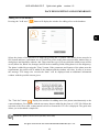
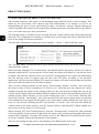
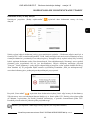
3.2. Connection with camera via web browser
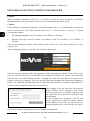
Enter the camera's IP address in the address bar of the web browser. If the provided address is correct
and the target device is currently available, the login page will be displayed.
Caution!
To ensure the correct operation of the function of saving photos and videos on the computer disk, the
web browser should be run with administrator rights.
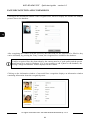
If the browser asks for it, install the NetAIIPCamera plug-in, which is necessary for the proper
operation of the camera menu. The lack of the correct add-on is indicated by the following message:
Click on the "Here" link to start downloading the add-on, then use your browser dialog to install it.
In the window, click the Run button, and then follow the instructions of the installer. After the
installation is completed, the browser window should be refreshed.
If other tabs were open in the browser window when installing the add-on, the installer will ask you to
close the browser. Then, after completing the installation, restart the IE browser and connect to the
camera.
NETWORK CONNECTION UTILIZING WEB BROWSER

NVIP-4SD-6540/25/F Quick start guide version 1.0
All rights reserved © AAT SYSTEMY BEZPIECZEŃSTWA Sp. z o.o.
16
Caution:
When working on Windows 7/8/8.1/10, it is possible to block the ActiveX add-on by Windows
Defender and User Account Control. In this case, you should allow the add-in to run.
Caution:
If the installation performed in the above-mentioned manner fails, it is recommended to change the
browser security level. To do this, select the menu: Tools -> Internet Options -> Security -> Custom
level and then change:
• Downloading unsigned ActiveX controls: set to "Enable" or "Prompt"
• Initialize and script ActiveX controls not marked as safe for execution: set to "Enable" or
"Prompt"
You can also add the IP address of the camera to the Trusted sites zone and set the zone to a low
security level.
After installing the plug-in, you will be able to log into the camera.
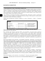
Enter the username and password in the appropriate fields (root, pass by default). In the "Stream type"
field, you can select the type of stream that will be displayed in the preview window after connection
(main stream or one of the auxiliary streams - changing the stream is also possible later, in the preview
window), and in the "Language" field, you can select the menu language (the default menu language is
Polish). The "Remember login and password" option allows the browser to remember login details. For
security reasons, using this option is not recommended.
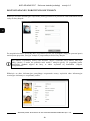
When logging in for the first time, the password
change window will be displayed. You should
select the Modify password option and then enter
and confirm the new password and confirm it with
the OK button.
To skip changing the password, click the OK
button. However, the password change window
will be displayed every time you log in until you
change your password or select Do not show again.
For security reasons, changing the password is highly recommended.
NETWORK CONNECTION UTILIZING WEB BROWSER

NVIP-4SD-6540/25/F Quick start guide version 1.0
All rights reserved © AAT SYSTEMY BEZPIECZEŃSTWA Sp. z o.o.
17
4. WEB INTERFACE - WORKING WITH THE CAMERA
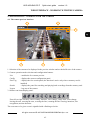
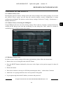
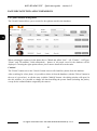
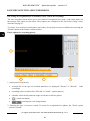
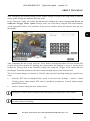
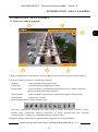
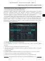
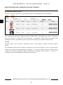
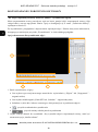
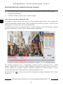
4.1. The remote preview interface
1. Selection of the stream to be displayed in the preview window and set the buffer size of the camera.
2. Camera operation mode selection and configuration buttons:
Live - enables the live stream preview
Config - displays the camera configuration panel
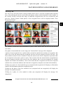
Face Log - displays the face search panel (the function is active only when a memory card is
installed)
Search - displays the panel for searching and playing back recordings from the memory card
Logout - logs out of the camera
3. Alarm event icons display panel:
From left to right: memory card recording indicator, color change, image blur, scene change,
leaving the area, entering the area, crossing the line, counting the line crossing, intrusion, face
recognition, motion detection.
The occurrence of a given event is signalled with a flashing red color.
WEB INTERFACE - WORKING WITH THE CAMERA
4
5
6
2
3
1

NVIP-4SD-6540/25/F Quick start guide version 1.0
All rights reserved © AAT SYSTEMY BEZPIECZEŃSTWA Sp. z o.o.
18
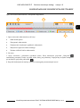
WEB INTERFACE - WORKING WITH THE CAMERA
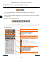
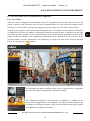
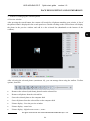
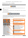
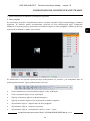
4. Image adjusting buttons:
From left to right: original size, original aspect ratio, automatic window fit, full screen.
5. Live view window.
Double-clicking the left mouse button on the preview window turns the display of the image on and
off in full screen.
6. Buttons for controlling camera functions:
From left to right: takes a photo, enables/disables recording, enables the 3D PTZ control, digital
zoom buttons, enables/disables the PTZ panel, enables/disables the panel displaying photos of
recognized faces with details (provided the recognized face is in the database)
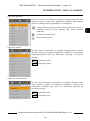
7. PTZ panel functions
Controlling the movement of the PTZ dome
Lens control buons, from the top:
zoom-, zoom+ focus-, focus+
iris-, iris+
List of presets, cruises or traces
Seng the speed of movement of the dome
Camera funcons control, from the le:
- on/o scanning
- on/o wiper (funcon inacve)
- IR illuminator control: turns on, turns on
automac mode, turns o
- enables 360 ° scanning
- enables group scanning
Changing the type of the displayed list:
- displays a list of presets
- displays the list of cruises
- displays a list of traces

NVIP-4SD-6540/25/F Quick start guide version 1.0
All rights reserved © AAT SYSTEMY BEZPIECZEŃSTWA Sp. z o.o.
19
WEB INTERFACE - WORKING WITH THE CAMERA
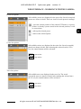
Preset list options:
All available presets are displayed in the preset list. Saved (occupied)
presets are shown in bold. There are icons for each preset to manage:
.
- saves the current position of the camera PTZ dome as a preset.
If there is already a preset stored in the selected position, it will
be overwritten.
- calls up the selected preset
- removes the selected preset
Cruise list options:
All available cruises are displayed in the cruise list. Saved (occupied)
patrols are shown in bold. After selecting the selected cruise (if it is
set), the control buttons will be activated:
.
- start cruise
- stop cruise
Trace list options:
All available traces are displayed in the trace list. The saved
(occupied) traces are shown in bold. After marking the selected trace
(if it is set), the control buttons will be activated:
.
- start trace
- stop trace

NVIP-4SD-6540/25/F Quick start guide version 1.0
All rights reserved © AAT SYSTEMY BEZPIECZEŃSTWA Sp. z o.o.
20
SD CARD INSTALLATION
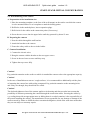
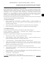
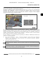
5. SD CARD INSTALLATION
The camera supports micro SD/SDHC cards up to 256 GB. In order to install the card:
• Turn off the power of the camera
• Remove the cover covering the back of the PTZ dome
• Install the SD card in the appropriate slot (indicated by the arrow in the figure below)
• Attach the cover paying attention to the correct position of the gasket
• Turn on the camera
• Check if the card is installed correctly by verifying its size in the tab "Settings -> System -> SD
card".
SD card slot
Reset buon
Strona się ładuje...
Strona się ładuje...
Strona się ładuje...
Strona się ładuje...
Strona się ładuje...
Strona się ładuje...
Strona się ładuje...
Strona się ładuje...
Strona się ładuje...
Strona się ładuje...
Strona się ładuje...
Strona się ładuje...
Strona się ładuje...
Strona się ładuje...
Strona się ładuje...
Strona się ładuje...
Strona się ładuje...
Strona się ładuje...
Strona się ładuje...
Strona się ładuje...
Strona się ładuje...
Strona się ładuje...
Strona się ładuje...
Strona się ładuje...
Strona się ładuje...
Strona się ładuje...
Strona się ładuje...
Strona się ładuje...
Strona się ładuje...
Strona się ładuje...
Strona się ładuje...
Strona się ładuje...
Strona się ładuje...
Strona się ładuje...
Strona się ładuje...
Strona się ładuje...
Strona się ładuje...
Strona się ładuje...
Strona się ładuje...
Strona się ładuje...
Strona się ładuje...
Strona się ładuje...
Strona się ładuje...
Strona się ładuje...
Strona się ładuje...
Strona się ładuje...
Strona się ładuje...
Strona się ładuje...
Strona się ładuje...
Strona się ładuje...
Strona się ładuje...
Strona się ładuje...
-
 1
1
-
 2
2
-
 3
3
-
 4
4
-
 5
5
-
 6
6
-
 7
7
-
 8
8
-
 9
9
-
 10
10
-
 11
11
-
 12
12
-
 13
13
-
 14
14
-
 15
15
-
 16
16
-
 17
17
-
 18
18
-
 19
19
-
 20
20
-
 21
21
-
 22
22
-
 23
23
-
 24
24
-
 25
25
-
 26
26
-
 27
27
-
 28
28
-
 29
29
-
 30
30
-
 31
31
-
 32
32
-
 33
33
-
 34
34
-
 35
35
-
 36
36
-
 37
37
-
 38
38
-
 39
39
-
 40
40
-
 41
41
-
 42
42
-
 43
43
-
 44
44
-
 45
45
-
 46
46
-
 47
47
-
 48
48
-
 49
49
-
 50
50
-
 51
51
-
 52
52
-
 53
53
-
 54
54
-
 55
55
-
 56
56
-
 57
57
-
 58
58
-
 59
59
-
 60
60
-
 61
61
-
 62
62
-
 63
63
-
 64
64
-
 65
65
-
 66
66
-
 67
67
-
 68
68
-
 69
69
-
 70
70
-
 71
71
-
 72
72


Novus NVIP-4SD-6540/25/F Instrukcja obsługi
- Kategoria
- Kamery ochrony
- Typ
- Instrukcja obsługi
w innych językach
- English: Novus NVIP-4SD-6540/25/F User manual
Powiązane artykuły
-
Novus NVIP-5VE-6201-II Instrukcja obsługi
-
Novus NVIP-4H-8002M Instrukcja obsługi
-
-
-
Novus NVIP-5H-6502M/F Instrukcja obsługi
-
-
-
-
-
Novus NVIP-4H-4231/WLAD Instrukcja obsługi