
Operating Instructions
Bedienungsanleitung
Instructions d’utilisation
Istruzioni per l’uso
Gebruiksaanwijzing
Manual de instrucciones
Brugsvejledning
Driftsföreskrifter
Bruksanvisning
Käyttöohjeet
Provozní pokyny
Használati utasítás
Cordless Drill & Driver
Akku-Bohrschrauber
Trapano avvitatore cordless
Snoerloze schroef-boormachine
Destornillador y taladro sin cables
Akku bor & skruetrækker
Sladdlös skruvdragare & borrmaskin
Ledningløs drill og skrutrekker
Ladattava pora & ruuvinväännin
Kablosuz Matkap ve Tahrik Birimi
Akkumulátoros fúró és csavarozó
Model No: EY74A3
Before operating this unit, please read these instructions completely and save this manual for future use.
Vor Inbetriebnahme des Gerätes die Betriebsanleitung bitte gründlich durchlesen und diese Broschüre zum späteren Nachschlagen
sorgfältig aufbewahren.
Prima di usare questa unità, leggere completamente queste istruzioni e conservare il manuale per usi futuri.
Lees deze gebruiksaanwijzing aandachtig door voor u het apparaat in gebruik neemt en bewaar de gebruiksaanwijzing voor eventuele naslag.
Antes de usar este aparato por primera vez, lea todas las instrucciones de este manual y guarde el manual para poderlo consultar en el futuro.
Gennemlæs denne betjeningsvejledning før brugen og gem den til fremtidig brug.
Läs igenom hela bruksanvisningen innan verktyget tas i bruk. Spara bruksanvisningen för senare användning.
Før enheten tas i bruk, vennligst les disse alle anvisningene og oppbevar deretter bruksanvisningen for senere bruk.
Lue ohjeet huolella ennen laitteen käyttöönottoa ja säilytä tämä käyttöohje tallessa tulevaa tarvetta varten.

- 2 -
English: Page 10
Deutsch: Seite 20
Italiano: Pagina 38
Nederlands: Bladzijde 47
Español: Página 56
Dansk: Side 65
Svenska: Sid 74
Norsk: Side 83
Polski: Strona 108
Magyar: Oldal 126
(Q)
(E)
(P)
(S)
(F)
(U)
(H)
(I)
(O)(N)(M)
(L) (K) (J)
(B)
(C)
(D)(A)
(G)
(R)
(T)

- 3 -
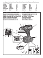
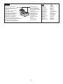
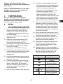
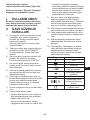
(A)
Keyless drill chuck
Schlüsselfreies Bohrfutter
Mandrino autoserrante
Boorkop zonder sleutel
Mandril sin llave
Nøglefri borepatron
Nyckellös borrchuck
Nøkkelfri drillchuck
Avaimeton poran kiinnityslaite
Bezkluczykowy uchwyt wiertarski
Kulcs nélküli fúrótokmány
(B)
Clutch handle
Kupplungsring
Poignée de l’embrayage
Impugnatura frizione
Koppelingshandgreep
Mango de embrague
Koblinghåndtag
Kopplingshandtag
Koblingshåndtak
Kytkimen kahva
Tengelykapcsolókar
(C)
Support handle mounting space
Befestigungsplatz für Zusatzgriff
Espace de montage du manche de support
Spazio per il montaggio della maniglia di sostegno
Steungreep montageruimte
Espacio de montaje del mango de soporte
Monteringssted for hjælpehåndtag
Monteringsmellanrum för stödhandtag
Monteringsplass for støttehåndtak
Tukikahvan asennustila
(D)
Speed selector switch
Bereichsschalter
Interrupteur de sélection de vitesse
Regolatore di velocità
Snelheidskeuzeschakelaar
Interruptor selector de velocidad
Hastighedsvælger
Hastighetsomkopplare
Hastighetskontroll
Nopeuden valintakytkin
Fordulatszám-választó kapcsoló
(E)
Forward/Reverse lever
Rechts/Linkslauf Schalter
Levier d’inversion marche avant-marche arrière
Leva di avanzamento/inversione
Voorwaarts/achterwaarts-hendel
Palanca de avance/inversión
Greb til forlæns/baglæns retning
Riktningsomkopplare
Forover/Revers bryter
Eteenpäin/taaksepäin vipu
Irányváltó kar
(F)
Belt hook
Riemenhaken
Crochet de ceinture
Gancio da cintura
Riemclip
Gancho del cinturón
Bæltekrog
Bälteskrok
Beltekrok
Vyölenkki
Zaczep paska
Hák na opasek
Övkampó
(G)
Battery pack
Akku
Batterie autonome
Pacco batteria
Accu
Batteripakning
Batteri
Batteripakke
Akku
Akumulator
Blok baterie
Akkumulátoregység
(H)
Battery pack release button
Akku-Entriegelungsknopf
Bouton de libération de batterie autonome
Tasto di rilascio pacco batteria
Accu-ontgrendeltoets
Udløserknap til batteripakning
Frigöringsknapp för batteri
Utløserknapp for batteripakke
Akkupaketin irrotuspainike
Przycisk zwolnienia blokady akumulatora
Akkumulátoregység kioldógombja

- 4 -
(I)
Control panel
Bedienfeld
Panneau de commande
Pannello di controllo
Bedieningspaneel
Panel de controle
Kontrolpanel
Kontrollpanel
Kontrollpanel
Säätöpaneeli
Kumanda paneli
(J)
Battery level button
Akkustandsanzeigeknopf
Bouton de niveau de la batterie
Tasto di livello della batteria
Knop accuniveau
Batteriniveauknap
Batterinivåknapp
Batterinivåknapp
Akun lataustaso
(K)
Battery level indicator/Speed setting
indicator
Akkustandsanzeige/Drehzahleinstellung-
sanzeige
Indicateur de niveau de la batterie/Indica-
teur de réglage de la vitesse
Indicatore di livello della batteria/Indicatore
di impostazione della velocità
Indicator accuniveau/Indicator snelheidsin-
stelling
de ajuste de la velocidad
Batteriniveauindikator/Hastighedsindikator
Batterinivåindikator/Varvtalsindikator
Batterinivåindikator/Indikator for hastighet-
sinnstilling
Akun lataustason ilmaisin/Nopeusasetuk-
sen ilmaisin
-
rychlosti
-
(L)
Speed setting button/Tap mode button
Drehzahleinstellungsknopf/Schrauben-
drehmodus-Taste
Bouton de réglage de la vitesse/Bouton du
mode taraud
Tasto di impostazione della velocità/Tasto
Snelheidsinstellingsknop/Tapmodus-knop
Botón de ajuste de la velocidad/Botón de
modo de roscador
Hastighedsvælgerknap/Skærende
skrue-indstillingsknappen
Varvtalsregleringsknapp/Slaglägesknapp
Knapp for hastighetsinnstilling/Gjengemo-
dus-knappen
Nopeusasetuspainike/Ruuvaustilapainike
trybu gwintowania
üzemmód gomb
(M)
Light button
Leuchtentaste
Bouton d’éclairage
Tasto della luce
Lichtknop
Botón de la luz
Lysknap
Lampknapp
Lysknapp
Valopainike
(N)
Tap mode indicator
Schraubendrehmodus-Anzeige
Indicateur du mode taraud
Tapmodus-indicator
Indicador de modo de roscador
Skærende skrue-indstillingsindikator
Slaglägesindikator
Gjengemodus-indikator
Ruuvaustilan merkkivalo

- 5 -
(O)
Overheat warning lamp (motor/battery)
Überhitzungs-Warnlampe (Motor/Akku)
Témoin d’avertissement de surchauffe
(moteur/batterie)
Spia avvertenza surriscaldamento (mo-
tore/batteria)
Oververhitting-waarschuwingslampje
(motor/accu)
Luz de advertencia de sobrecalentamiento
Advarselslamp til overophedning (motor/
batteri)
Varningslampa för överhettning (motor/
batteri)
Varsellampe for overoppheting (motor/
batteri)
Ylikuumenemisen varoituslamppu (mootto-
ri/akku)
Lampka ostrzegawcza przegrzania (silnik/
akumulator)
(motor/akkumulátor)
(P)
Variable speed control trigger
Betriebsschalter
Gâchette de commande de vitesse
Grilletto di controllo velocità variable
Startschakelaar variabele snelheid
Disparador del control de velocided
variable
Kontroludløser for variabel hastighed
Steglös varvtalsreglerare
Hovedbryter, trinnløs
Nopeudensäätökytkin
i
l
(Q)
LED light
LED-Leuchte
Lumière DEL
Luce LED
LED-lampje
Luz indicadora
LED-lys
LED-ljus
LED-lys
LED-valo
Lampka LED
LED-lámpa
(R)
Battery charger
Ladegerät
Chargeur de batterie
Caricabatterie
Acculader
Batterioplader
Batteriladdare
Batterilader
Akkulaturi
(S)
Alignment marks
Ausrichtmarkierungen
Marques d’alignement
Marcature allineamento
Uitlijntekens
Marcas de alineación
Flugtemærker
Anpassningsmärken
Opprettingsmerke
Sovitusmerkit
Znaczniki
(T)
Pack cover
Akkuabdeckung
Couvercle de la batterie autonome
Coperchio pacco
Accudeksel
Pakningsdæksel
Batteriskydd
Pakkedeksel
Akkukotelon kansi
Kryt bloku
Az akkumulátoregység fedele

- 6 -
(U)
Spare bit storage
Ersatzbit-Ablage
Rangement des mèches de rechange
Magazzino punte di scorta
Reserve-bitopslag
Almacenamiento de brocas de recambio
Magasin til ekstra bit
Förvaring av reservbett
Reservebit-lager
Varaterien säilytyslaatikko
Tartalék fej tároló
NOTE: Not all battery packs display the alignment mark (S).
HINWEIS: Nicht auf allen Akkus ist eine Ausrichtungsmarkierung (S) zu sehen.
REMARQUE: Certaines batteries autonomes ne présentent pas de marque d’alignement (S).
NOTA: Non tutti i pacchi batteria riportano la marcatura di allineamento (S).
OPMERKING: Op niet alle accu’s wordt het uitlijningsteken (S) weergegeven.
OBSERVERA: Alla batterier har inte anpassningsmärken (S).
MERK: Ikke alle batteripakker viser justeringsmerket (S).
HUOMAUTUS: Kaikissa akuissa ei ole kohdistusmerkintää (S).

- 7 -
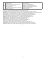
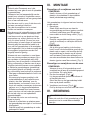
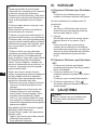
[Fig.1] [Fig.2]
(A)
[Fig.3]
[Fig.4]
Attaching
Anbringen
Connexion
Collegamento
Bevestigen
Acoplamiento
Påsætning
Montering
Montering
Kiinnittäminen
Takma
Mocowanie
Csatlakoztatás
Removing
Entfernen
Retrait
Rimozione
Verwijderen
Desacoplamiento
Aftagning
Lossdragning
Demontering
Irrottaminen
Alignment marks
Ausrichtmarkierungen
Marques d’alignement
Marcature allineamento
Uitlijntekens
Marcas de alineación
Flugtemærker
Anpassningsmärken
Opprettingsmerke
Sovitusmerkit
Znaczniki
Button
Knopf
Bouton
Tasto
Knop
Botón
Knap
Frigöringsknapp
Knapp
Painike
Przycisk
Gomb
[Fig.5]
Reverse
Links
Rotation en sens
inverse
Inversione
Links
Marcha atrás
Baglæns
Bakåt
Bakover
Taaksepäin
Geri
Lewo
Dozadu
Balra
Forward
Rechts
Rotation en sens normal
Avanti
Rechts
Avance
Forlæns
Framåt
Forover
Eteenpäin
Prawo
Jobbra
Switch lock
Schaltersperre
Verrouillage du
commutateur
Blocco interruttore
Vergrendelstand
Bloqueo delinterruptor
Omskifterlås
Låst läge
Bryterlås
Kytkinlukko
Anahtar kilidi
Kapcsoló retesze
[Fig.6]

- 8 -
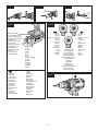
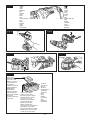
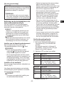
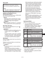
[Fig.12]
Pack cover
Akkuabdeckung
Couvercle de la
batterie autonome
Coperchio pacco
Accudeksel
Pakningsdæksel
Batteriskydd
Pakkedeksel
Akkukotelon kansi
Kryt bloku
Az akkumulátoregy-
ség fedele
Terminals
Anschlüsse
Bornes
Terminali
Aansluitpunten
Terminales
Terminaler
Poler
Ender
Liittimet
Terminaller
Styki
Konektory
Label (red or yellow)
Etikett (rot oder gelb)
Etiquette (rouge ou jaune)
Etichetta (rossa o gialla)
Label (rood of geel)
Etiqueta (roja o amarilla)
Label (rødt eller gult)
Etikett (röd eller gul)
Etikett (rød eller gul)
Tarra (punainen tai keltainen)
[Fig.8]
[Fig.11]
[Fig.10]
[Fig.7]
LOW
NIEDRIG
BAS
BASSO
LAAG
BAJA
LAV
LAV
PIENI
LOW
NÍZKÝ
ALACSONY
HIGH
HOCH
HAUT
ALTO
HOOG
ALTA
HØJ
HÖGA VARVTAL
HØY
SUURI
YÜKSEK
HIGH
VYSOKÝ
MAGAS

[Fig.13]
Attaching
Anbringen
Connexion
Collegamento
Bevestigen
Acoplamiento
Påsætning
Montering
Montering
Kiinnittäminen
Takma
Mocowanie
Csatlakoztatás
Removing
Entfernen
Retrait
Rimozione
Verwijderen
Desacoplamiento
Aftagning
Lossdragning
Demontering
Irrottaminen
Alignment marks
Ausrichtmarkierungen
Marques d’alignement
Marcature allineamento
Uitlijntekens
Marcas de alineación
Flugtemærker
Anpassningsmärken
Opprettingsmerke
Sovitusmerkit
Znaczniki
Battery pack release button
Akku-Entriegelungsknopf
Bouton de libération de batterie
autonome
Tasto di rilascio pacco batteria
Accu-ontgrendeltoets
Udløserknap til batteripakning
Frigöringsknapp för batteri
Utløserknapp for batteripakke
Akkupaketin irrotuspainike
Przycisk zwolnienia blokady akumulatora
Akkumulátoregység kioldógombja

- 10 -
EN
Other languages
and the following before using.
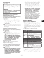
I.
II.
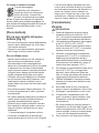
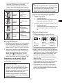
1) If the bit becomes jammed, immedi-
ately turn the trigger switch off to
prevent an overload, which can
damage the battery pack or motor.
Use reverse motion to loosen jammed
bits.
2) Do NOT operate Forward/Reverse
lever when the trigger switch is on.
The battery will discharge rapidly and
damage to the main unit may occur.
3) During charging, the charger may
become slightly warm. This is normal.
Do NOT charge the battery for a long
period.
4) Do not strain the tool by holding the
speed control trigger halfway (speed
control mode) so that the motor stops.
5) To prevent injury during use, hold the
tool steady at all times and avoid
waving it around.
6) Ensure that there are no hidden gas
or water pipes in the area in which
you will be working. Contact with
hidden pipes or wires could cause
electric shock or water or gas leaks.
7) Make sure to hold the object you are
working on steady.
8) Check for damaged parts.
• Check thoroughly for damage to the
protective cover and other parts
before operating.
• Check to make sure the tool and all
of its functions are working properly.
• Check the adjustment of all movable
and free of damage. Check all parts
of the tool for abnormal function.
When attempting to repair the protec-
tive cover or other parts, please follow
the instructions in the user manual. In
cases where there are no instructions
in the manual, please take it back to
the store to have it repaired.
10) If the tool gets exceptionally hot
during use, please take it in for
service and repair.
11) To avoid potential injury, keep face
and hands away from the drill bit and
any shavings.
12) Do not wear gloves when operating
the tool, as they may get caught by
the drill, leading to injury.
13) Battery terminals, screw shavings,
and tool accessories such as drill bits
will be very hot immediately after
operation. Do not touch them as there
is a risk of burning yourself.
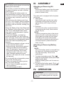
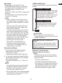
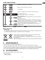
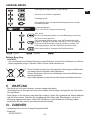
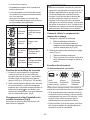
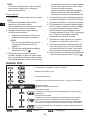
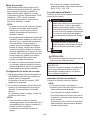
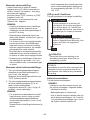
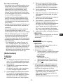
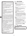
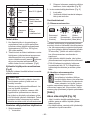
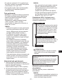
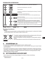
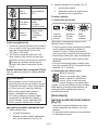
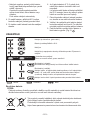
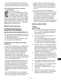
Meaning
Volts
Direct current
No load speed
Revolutions or recip-
rocations per minutes
Electrical capacity of
battery pack
Rotation only
Read the operating
instructions before
use.
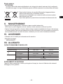
For indoor use only.
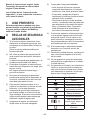
• Do not use other than the Panasonic
battery packs that are designed for use
with this rechargeable tool.
• Panasonic is not responsible for any
damage or accident caused by the use
of recycled or counterfeit battery pack.
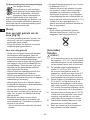
• Do not dispose of the battery pack in a

- 11 -
EN
• Do not allow metal objects to touch the
battery pack terminals.
• Do not carry or store the battery pack in
the same container as nails or similar
metal objects.
• Do not charge the battery pack in a
high-temperature location, such as next
explode.
• After removing the battery pack from
the tool or the charger, always reattach
the pack cover. Otherwise, the battery
contacts could be shorted, leading to a
• When the Battery Pack Has Deteriorat-
ed, Replace It with a New One. Contin-
ued use of a damaged battery pack
may result in heat generation, ignition
or battery rupture.
• To prevent leakage, overheating,
from occurring, follow these instructions
when handling our rechargeable power
tools (tool main body/battery pack/
charger).
- Do not allow material cuttings or dust
to fall onto the battery pack.
- Before storing, remove any material
cuttings and dust from the battery
then place separately from metal
objects (screws, nails, etc.) in tool
case. Damage caused by loose
objects in the case will not be covered
by warranty.
• Do not handle the rechargeable power
tools in the following way.
(There is a hazard of smoke genera-
- Use or leave in places exposed to
rain or moisture
- Use submerging in water
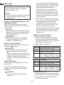
III.
Disconnect battery pack from the main
unit or place the switch in the center
position (switch lock).
The main unit is equipped with a keyless
drill chuck.
1. Attachment
Insert the bit and turn the lock collar
clockwise (looking from the front) to
[Fig.1]
2. Removal
Turn the lock collar counterclockwise
(looking from the front), then remove
the bit. [Fig.2]
If there is excessive play in the chuck,
secure the drill in place and open the
chuck jaws by turning the lock collar
and tighten the screw (left-handed
screw) with a screwdriver by turning it
counterclockwise (viewed from the
front). [Fig.3]
Pack
When the battery pack is removed from
the main unit, the control panel lamp
malfunction.
1. To attach the battery pack: [Fig.4 ]
Align the highlighted marker points and
attach battery pack.
Slide the battery pack until it locks into
position.
2. To remove the battery pack: [Fig.4 ]
Push the button and slide the battery
pack forward.
• Do not inhale smoke emitted from the
main unit or battery pack as it may be
harmful.

- 12 -
EN
[Main Unit]
When storing or carrying the tool, set the
Forward/Reverse lever to the center
position (switch lock).
Exercise caution to ensure no objects
come into contact with the tool’s
trigger switch.
Operation [Fig.5]
Push the lever for forward or reverse
rotation. Check the direction of the lever
before using.
When operating the tool by pulling the
trigger, there may be a momentary lag
before rotation starts. This does not
signal a malfunction.
To prevent damage, do not operate
Forward/Reverse lever until the bit
comes to a complete stop.
Adjust the torque to one of the 18 clutch
• Set the clutch setting at this mark
[Fig.6] before actual operation.
• If the clutch handle cannot be set at
function, set the clutch handle at
position 1 and operate the clutch for a
second.
Choose a low or high speed to suit the
use. [Fig.7]
The more the variable speed control
trigger is pulled, the higher the speed
becomes.
• Check the speed selector switch
before use.
• Use in low gear when high torque is
required in operation. (Using in high
gear with high load can cause motor
overload and possible failure.)
• To prevent excessive temperature
increase of the tool surface, do not
operate the tool continuously using
two or more battery packs. The tool
needs cool-off time before switching
to another pack.
• Ensure that air vents on the sides of the
main unit are not blocked during operation.
Covering them can cause the tool to
overheat and motor damage to occur.
• Do NOT strain the tool (motor). This
may cause damage to the tool.
• Avoid contact with air from vent holes
during operation as under heavy load
this can become hot and potentially
cause injury.
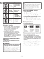
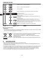
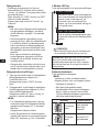
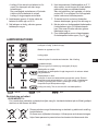
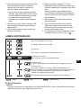
Setting the maximum speed.
1. Press the Speed setting button/Tap
mode button (L) and select a speed.
The speed changes to H, M, L and OFF
(the light is off) in this order.
2. Select OFF to release it.
Display Low mode
H Approx. 300 min
-1
(rpm)
M Approx. 200 min
-1
(rpm)
L Approx. 150 min
-1
(rpm)
OFF Ordinary speed
18 V Approx. 530 min
-1
(rpm)
14.4 V Approx. 430 min
-1
(rpm)
Display High mode
H Approx. 1000 min
-1
(rpm)
M Approx. 670 min
-1
(rpm)
L Approx. 500 min
-1
(rpm)
OFF Ordinary speed
18 V Approx. 1800 min
-1
(rpm)
14.4 V Approx. 1450 min
-1
(rpm)
• Default setting: OFF
• The speed is the same using either 14.4 V
or 18 V when H, M, L settings are selected.
• If a high mode is chosen, the speed is
set as the table above.

- 13 -
EN
• Regardless of the position of the
Forward/Reverse lever (E), every time
the trigger switch is pressed, the drill
working.
The lamp lights up in accordance with
• When using the Tap mode function,
the tap drill may be damaged, so set
the clutch handle at position 1 before
use.
• Tip tools (tap drills) may slip during
work depending on the shape, type,
and surface condition.
In order to ensure safe and accurate
work, before starting work or during
work, check that the tip tool (tap drill)
is securely tightened with the keyless
drill chuck. Also, use a hexagonal
shaft type tip tool (tap drill) with high
holding force when you wish to
perform more accurate work.
• Tap mode is cancelled when no
operation is performed for about
5 minutes or immediately after the
battery pack is removed.
1. Press and hold the Speed setting
button/Tap mode button (L) for
2 seconds or longer.
2. In Tap mode, press the Speed setting
button/Tap mode button (L) to change
the rotational speed.
The speed changes to L, H, M in this
order.
• To cancel Tap mode, press and hold
the Speed setting button/Tap mode
button (L) for 2 seconds or longer.
The Tap mode lamp turns off.
• During Tap mode, the rotational speed
is the same for motor voltage of both
18 V DC and 14.4 V DC
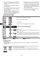
Press the light button to select illumination
setting.
Illuminated - Constant
Select by pressing lamp button light
will activate when trigger is pressed.
It will then stay illuminated for
approximately 5 minutes even if tool
is not used but will then switch off
automatically to save power.
Illuminated - On trigger
By pressing the lamp button again,
the mode will move to illumination
upon the pressing of the trigger
only.
Off
Do not use it as a substitute for a
enough brightness.
DO NOT STARE INTO
BEAM.
Use of controls or adjustments or perfor-
mance of procedures other than those
radiation exposure.
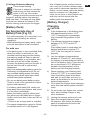
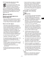
Press the battery level button.
The indicator will not show the battery
level when the button is pressed in the
following cases.
• The tool is powered off.
• Just after attaching the battery pack
• The main unit or battery level button is
Press the battery level button again
after depressing the trigger switch.

- 14 -
EN
Indicator Battery status
3 lamps
illuminated
Fully charged
or high charge
level
2 lamps
illuminated
Approx. 60%
remaining
One lamp
illuminated
Low level
- Will require
charging soon
3 lamps
Empty
- Immediate
charging
required
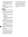
Bit-locking Function
1. With the trigger switch not depressed
and a screwdriver bit locked in place,
the tool can be used as a manual
screwdriver (up to 22.6 N•m,
230 kg
2. This feature is handy for tightening
screws that require more torque than
the maximum torque of the driver
(position
the tightness of a screw or to loosen an
extremely tight screw. [Fig.8]
The belt hook can be attached to either
side of the unit.
• Be sure to attach the belt hook securely
fastened.
• Periodically check screw for tightness.
• When the tool is held by the belt hook,
avoid jumping or running with it.
• When the tool is hooked onto the waist
belt by the belt hook, do not attach
driver bits to the tool. A sharp edge
object, such as a drill bit, may cause
injury or an accident.
How to use spare bit storage
1. Store spare bits.
1 Remove the battery pack.
2 Push it all the way into the spare bit
storage as shown in [Fig.10].
2. Remove spare bit from storage. [Fig.11]
1 Remove the battery pack.
2 Pull out the bit tip on the rear side
of the spare bit and take out the bit.
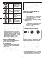
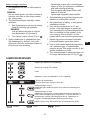
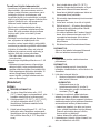
Warning Functions
(1) Overheat Warning
Off
(normal
operation)
Illuminated:
Overheat
(motor)
Flashing:
Overheat
(battery)
Indicates operation has been halted due to
motor or battery overheating.
• If the overheating protection feature
activates, allow the tool to cool thorough-
ly (at least 30 minutes). The tool is ready
for use when the overheat warning lamp
goes out.
• Avoid using the tool in a way that causes
the overheating protection feature to
activate repeatedly.
• -
to work conditions and other factors.

- 15 -
EN
If the tool is subject to a sudden
load during use that causes the
motor to lock up, the overdis-
charge prevention sensor may be
triggered, and the battery low warning
-
ing once you address the cause of the
motor’s locking up and cycle the trigger.
[Battery Pack]
Battery Pack [Fig.12]
• For optimum battery life, store the Li-ion
battery pack following use without
charging it.
• When operating the battery pack, make
sure the work place is well ventilated.
For safe use
•
when the switch is switched on, the
overheat warning lamp and the battery
that safe operation is not possible, and
the main unit will not rotate normally.
Connect the battery pack into the unit of
the tool until the red or yellow label
disappears.
• Only use rechargeable battery packs for
Panasonic rechargeable tools. Do not
battery packs which have been disas-
sembled and parts replaced).
• Do not use deteriorated battery packs.
There is a risk of the generation of heat,
ignition and explosion.
•
it to the store immediately.
• Attach the battery pack by sliding until
the yellow and red labels are no longer
visible, and check that it does not fall out
of place.
- Failure to do so may result in scalding.
• The usage temperature range for lithium
ion battery packs is 0 to 40 degrees.
- Use of battery packs cooled to below
zero, such as in colder northern areas,
may result in abnormal operation of the
device. In such cases, leave the battery
pack in a location of 10 degrees or
more for one hour or more before use,
and only use the device after the
battery pack has warmed up.
[Battery Charger]
Charging
1) If the temperature of the battery pack
stop to prevent degradation of the
battery.
2) The ambient temperature range is
If the battery pack is used when the
properly.
3) Use the charger at temperatures
the battery at a temperature similar to
that of the battery itself. (There should
between the temperatures of the
battery and the charging location.)
4) When charging a cool battery pack
leave the battery pack at the place
and wait for more than one hour to
warm up the battery to the level of the
ambient temperature.
5) Cool down the charger when charging
more than two battery packs consecu-
tively.
6)
hole, when holding charger or any
other occasions.
7) Unplug the charger when not in use.
8) Store the charger between 0 and
40 degrees, and charge the battery
pack at a temperature close to the
storage temperature.

- 16 -
EN
• If the battery pack is charged while at
a temperature below 0 degrees, a full
charge will give only around 50% of a
normal charge. Commence charging
after 1 hour or more at the prescribed
temperature.
Do not charge in a poorly ventilated
place.
Your battery pack is not fully charged at
the time of purchase. Be sure to charge
the battery before use.
How to charge
1. Plug the charger into the AC outlet.
Sparks may be produced when the plug
is inserted into the AC power supply,
but this is not a problem in terms of
safety.
charger.
1 Line up the alignment marks and
place the battery onto the dock on
the charger.
Not all battery packs display the
alignment mark (S) (on page 2).
2 Slide forward in the direction of the
arrow. [Fig.13 ]
3. During charging, the charging lamp will
be lit. When charging is completed, an
internal electronic switch will automati-
cally be triggered to prevent overcharg-
ing.
• Charging will not start if the battery
pack is hot (for example, immediately
after heavy-duty operation).
The orange standby lamp will be
Charging will then begin automatically.
slowly once the battery is approximate-
ly 80% charged.
5. When charging is completed, the
charging lamp in green color will turn
off.
6. If the temperature of the battery pack is
fully charge the battery pack than the
standard charging time.
Even when the battery is fully charged,
it will have approximately 50% of the
power of a fully charged battery at
normal operating temperature.
7. Consult an authorized dealer if the
charging lamp (green) does not turn off.
8. If a fully charged battery pack is insert-
ed into the charger again, the charging
lamp lights up. After several minutes,
the charging lamp in green color will
turn off.
battery pack release button is held up.
[Fig.13 ]

- 17 -
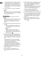
EN
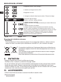
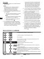
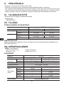
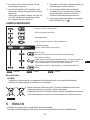
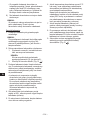
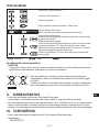
Charging is completed. (Full charge.)
Battery is approximately 80% charged.
Now charging.
Turn off Illuminated
Flashing
Charger is plugged into the AC outlet. Ready to charge.
Charging Status Lamp.
Left: green Right: orange will be displayed.
Battery pack is cool.
The battery pack is being charged slowly to reduce the load on
the battery.
Battery pack is warm.
Charging will begin when temperature of battery pack drops. If
when the temperature of the battery pack goes up.
Charging is not possible. Clogged with dust or malfunction of
the battery pack.
(Green) (Orange)
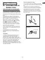
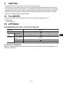
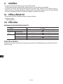
Battery Recycling
For environmental protection and recycling of materials, be sure that it is disposed of at
These symbols indicate separate collection of waste electrical
and electronic equipment or waste batteries.
More detailed information is contained in the full version Operat-
ing Instructions.
https://www.panasonic-powertools.eu/en/construction/documents.htm
• Use only a dry, soft cloth for wiping the unit.
Do not use a damp cloth, thinner, benzine, or other volatile solvents for cleaning.
• In the event that the inside of the tool or battery pack is exposed to water, drain and allow
tool. If you experience any problems operating the tool, consult with a repair shop.
• Use only bits suitable for size of drill’s chuck.
• Support handle
WEY6470K3217

- 18 -
EN
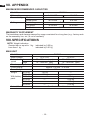
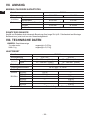
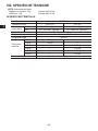
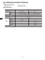
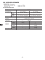
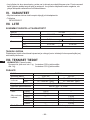
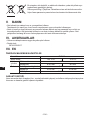
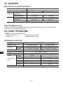
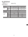
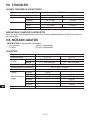
Model No. EY74A3
Motor voltage 14.4 V DC 18 V DC
Screw driving Machine screw M5
Wood screw
Drilling Self-drilling screw
For Wood
For Metal
The breakdown and damage caused by usage consistent for a long time (e.g.: factory work
on the assembly line, etc.) is out of warranty.
Weight indication
Greater than or equal to 1 kg: indicated by 0.05 kg.
Less than 1 kg: indicated by 0.01 kg.
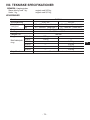
Model No. EY74A3
Motor voltage 14.4 V DC 18 V DC
No load
speed
Low 20 – 430 min
-1
(rpm) 20 – 530 min
-1
(rpm)
High
70 – 1450 min
-1
(rpm) 70 – 1800 min
-1
(rpm)
Chuck capacity
Clutch torque Approx. 0.5 N•m – 4.4 N•m
Overall length
Weight
With battery
pack:
1.55 kg —
1.35 kg —
— g
— 2.00 kg
— 1.75 kg
— 2.00 kg
Noise, Vibration See the included sheet

EN
This appliance is supplied with a moulded
three pin mains plug for your safety and
plug.
Should the fuse need to be replaced
please ensure that the replacement fuse
has a rating of 5 amp and that it is
approved by ASTA or BSI to BS1362.
Check for the ASTA mark or the BSI
mark on the body of the fuse.
If the plug contains a removable fuse
when the fuse is replaced.
If you lose the fuse cover the plug must
not be used until a replacement cover is
obtained.
A replacement fuse cover can be
purchased from your local Panasonic
Dealer.
IF THE FITTED MOULDED PLUG IS
UNSUITABLE FOR THE SOCKET
OUTLET IN YOUR HOME THEN THE
FUSE SHOULD BE REMOVED AND THE
PLUG CUT OFF AND DISPOSED OF
SAFELY. THERE IS A DANGER OF
SEVERE ELECTRICAL SHOCK IF THE
CUT OFF PLUG IS INSERTED INTO ANY
13 AMP SOCKET.
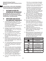
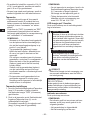
How to replace the fuse
The location of the fuse differs according
B).
follow the instructions below. Illustrations
may differ from actual AC mains plug.
Open the fuse cover with a screwdriver
and replace the fuse and close or attach
the fuse cover.
Figure B
Fuse Cover

- 20 -
DE
I.
II.
1) Falls das Bit stecken bleibt, lassen Sie
sofort den Elektronikschalter los, um eine
Überlastung zu verhüten, die den Akku
oder Motor beschädigen kann.
Verwenden Sie die Rückwärtsdrehung, um
klemmende Bits zu lösen.
2) Betätigen Sie den Rechts-/Linkslauf-Um-
schalthebel NICHT, wenn der Hauptschal-
ter eingeschaltet ist.
Der Akku entlädt sich schnell, und Schä-
den am Hauptgerät können auftreten.
3)
etwas erhitzen. Dies ist normal.
Den Akku daher NICHT über lange Zeit
4) Belasten Sie das Werkzeug nicht, indem
Sie den Elektronikschalter halb gedrückt
halten (Drehzahlregelmodus), sodass der
Motor stehen bleibt.
5) Um Verletzungen während des Gebrauchs
zu vermeiden, halten Sie das Werkzeug
immer fest und vermeiden, es herumzu-
schwenken.
6)
Stellen Sie sicher, dass keine versteckten
Gas- oder Wasserrohre im beabsichtigten
Arbeitsbereich vorhanden sind. Ein unbe-
absichtigter Kontakt mit versteckten Rohren
oder Leitungen kann zu Stromschlägen
oder Wasser- bzw. Gaslecks führen.
7) Achten Sie darauf, den Gegenstand, an
dem Sie arbeiten, richtig festzuhalten.
8) Prüfen Sie, ob beschädigte Teile vorhan-
den sind.
• Prüfen Sie vor der Inbetriebnahme Schutzabde-
ckung und andere Teile gründlich auf Schäden.
• Stellen Sie sicher, dass das Werkzeug und
alle seine Funktionen korrekt arbeiten.
• Kontrollieren Sie die Anpassung aller bewegli-
chen Teile, und überprüfen Sie alle festen
Teile, um sicherzustellen, dass sie richtig
eingebaut wurden und frei von Schäden sind.
Überprüfen Sie alle Teile des Werkzeugs auf
einwandfreie Funktionstüchtigkeit.
Wenn Sie versuchen, die Schutzabdeckung
oder andere Teile zu reparieren, befolgen Sie
bitte die Anweisungen im Benutzerhandbuch.
In Fällen, wo es keine Anleitungen im Hand-
buch gibt, bringen Sie das Gerät zurück in
den Laden, um es dort reparieren zu lassen.
10)
Wenn das Werkzeug während des
Gebrauchs außergewöhnlich heiß wird,
bringen Sie es bitte zurück zum Fachhändler,
um es dort warten und reparieren zu lassen.
11) Um mögliche Verletzungen zu vermeiden,
halten Sie Gesicht und Hände von Bohrer
und Spänen entfernt.
12) Tragen Sie keine Handschuhe beim
Gebrauch des Werkzeugs, da diese in den
Bohrer gelangen und Verletzungen
verursachen können.
13) Batterieanschlüsse, Schraubenspäne und
Werkzeugzubehör wie Bohreinsätze sind
unmittelbar nach dem Betrieb sehr heiß.
Berühren Sie diese nicht, da die Gefahr
von Verbrennungen besteht.
Bedeutung
Volt
Gleichstrom
Leerlaufdrehzahl
Drehzahl oder Hubzahl
pro Minute
Akkukapazitat in
Ampere Stunden
Nur Drehung
Lesen Sie die Bedienungs-
anleitung vor Gebrauch.
Nur für Inneneinsatz.
Strona się ładuje...
Strona się ładuje...
Strona się ładuje...
Strona się ładuje...
Strona się ładuje...
Strona się ładuje...
Strona się ładuje...
Strona się ładuje...
Strona się ładuje...
Strona się ładuje...
Strona się ładuje...
Strona się ładuje...
Strona się ładuje...
Strona się ładuje...
Strona się ładuje...
Strona się ładuje...
Strona się ładuje...
Strona się ładuje...
Strona się ładuje...
Strona się ładuje...
Strona się ładuje...
Strona się ładuje...
Strona się ładuje...
Strona się ładuje...
Strona się ładuje...
Strona się ładuje...
Strona się ładuje...
Strona się ładuje...
Strona się ładuje...
Strona się ładuje...
Strona się ładuje...
Strona się ładuje...
Strona się ładuje...
Strona się ładuje...
Strona się ładuje...
Strona się ładuje...
Strona się ładuje...
Strona się ładuje...
Strona się ładuje...
Strona się ładuje...
Strona się ładuje...
Strona się ładuje...
Strona się ładuje...
Strona się ładuje...
Strona się ładuje...
Strona się ładuje...
Strona się ładuje...
Strona się ładuje...
Strona się ładuje...
Strona się ładuje...
Strona się ładuje...
Strona się ładuje...
Strona się ładuje...
Strona się ładuje...
Strona się ładuje...
Strona się ładuje...
Strona się ładuje...
Strona się ładuje...
Strona się ładuje...
Strona się ładuje...
Strona się ładuje...
Strona się ładuje...
Strona się ładuje...
Strona się ładuje...
Strona się ładuje...
Strona się ładuje...
Strona się ładuje...
Strona się ładuje...
Strona się ładuje...
Strona się ładuje...
Strona się ładuje...
Strona się ładuje...
Strona się ładuje...
Strona się ładuje...
Strona się ładuje...
Strona się ładuje...
Strona się ładuje...
Strona się ładuje...
Strona się ładuje...
Strona się ładuje...
Strona się ładuje...
Strona się ładuje...
Strona się ładuje...
Strona się ładuje...
Strona się ładuje...
Strona się ładuje...
Strona się ładuje...
Strona się ładuje...
Strona się ładuje...
Strona się ładuje...
Strona się ładuje...
Strona się ładuje...
Strona się ładuje...
Strona się ładuje...
Strona się ładuje...
Strona się ładuje...
Strona się ładuje...
Strona się ładuje...
Strona się ładuje...
Strona się ładuje...
Strona się ładuje...
Strona się ładuje...
Strona się ładuje...
Strona się ładuje...
Strona się ładuje...
Strona się ładuje...
Strona się ładuje...
Strona się ładuje...
Strona się ładuje...
Strona się ładuje...
Strona się ładuje...
Strona się ładuje...
Strona się ładuje...
Strona się ładuje...
Strona się ładuje...
Strona się ładuje...
-
 1
1
-
 2
2
-
 3
3
-
 4
4
-
 5
5
-
 6
6
-
 7
7
-
 8
8
-
 9
9
-
 10
10
-
 11
11
-
 12
12
-
 13
13
-
 14
14
-
 15
15
-
 16
16
-
 17
17
-
 18
18
-
 19
19
-
 20
20
-
 21
21
-
 22
22
-
 23
23
-
 24
24
-
 25
25
-
 26
26
-
 27
27
-
 28
28
-
 29
29
-
 30
30
-
 31
31
-
 32
32
-
 33
33
-
 34
34
-
 35
35
-
 36
36
-
 37
37
-
 38
38
-
 39
39
-
 40
40
-
 41
41
-
 42
42
-
 43
43
-
 44
44
-
 45
45
-
 46
46
-
 47
47
-
 48
48
-
 49
49
-
 50
50
-
 51
51
-
 52
52
-
 53
53
-
 54
54
-
 55
55
-
 56
56
-
 57
57
-
 58
58
-
 59
59
-
 60
60
-
 61
61
-
 62
62
-
 63
63
-
 64
64
-
 65
65
-
 66
66
-
 67
67
-
 68
68
-
 69
69
-
 70
70
-
 71
71
-
 72
72
-
 73
73
-
 74
74
-
 75
75
-
 76
76
-
 77
77
-
 78
78
-
 79
79
-
 80
80
-
 81
81
-
 82
82
-
 83
83
-
 84
84
-
 85
85
-
 86
86
-
 87
87
-
 88
88
-
 89
89
-
 90
90
-
 91
91
-
 92
92
-
 93
93
-
 94
94
-
 95
95
-
 96
96
-
 97
97
-
 98
98
-
 99
99
-
 100
100
-
 101
101
-
 102
102
-
 103
103
-
 104
104
-
 105
105
-
 106
106
-
 107
107
-
 108
108
-
 109
109
-
 110
110
-
 111
111
-
 112
112
-
 113
113
-
 114
114
-
 115
115
-
 116
116
-
 117
117
-
 118
118
-
 119
119
-
 120
120
-
 121
121
-
 122
122
-
 123
123
-
 124
124
-
 125
125
-
 126
126
-
 127
127
-
 128
128
-
 129
129
-
 130
130
-
 131
131
-
 132
132
-
 133
133
-
 134
134
-
 135
135
-
 136
136


w innych językach
- čeština: Panasonic EY74A3 Operativní instrukce
- español: Panasonic EY74A3 Instrucciones de operación
- italiano: Panasonic EY74A3 Istruzioni per l'uso
- Deutsch: Panasonic EY74A3 Bedienungsanleitung
- svenska: Panasonic EY74A3 Bruksanvisningar
- français: Panasonic EY74A3 Mode d'emploi
- Türkçe: Panasonic EY74A3 Kullanma talimatları
- English: Panasonic EY74A3 Operating instructions
- dansk: Panasonic EY74A3 Betjeningsvejledning
- suomi: Panasonic EY74A3 Käyttö ohjeet
- Nederlands: Panasonic EY74A3 Handleiding
Powiązane artykuły
-
Panasonic EY79A2 Instrukcja obsługi
-
-
-
Panasonic EY75A7 Instrukcja obsługi
-
-
-
-
-
-