
Quick Installation Guide
ASW30K-LT-G2/ ASW33K-LT-G2
ASW36K-LT-G2/ ASW40K-LT-G2
ASW45K-LT-G2/ ASW50K-LT-G2
English ________________________________________ Quick installation guide
Српски ___________________________________Кратки водич за инсталацију
Dansk _____________________________________ Snelle installatiehandleiding
Deutsche ___________________________________ Schnellinstallationsanleitung
Español ______________________________________Guía de instalación rápida
Français ____________________________________Manuel d’installation rapide
Hrvatski _______________________________________ Kratki vodič za montažu
Magyar ______________________________________ Gyors telepítési útmutató
Polski ____________________________________ Instrukcja szybkiego montażu
Português ___________________________________ Guia de Instalação Rápida
Türk ___________________________________________ Hızlı Kurulum Kılavuzu

TABLE OF CONTENTS
English __________________________________________ 1
Српски ___________________________________________ 7
Dansk ___________________________________________ 13
Deutsche ________________________________________ 19
Español _________________________________________ 25
Français _________________________________________ 31
Hrvatski _________________________________________ 37
Magyar __________________________________________ 43
Polski ___________________________________________ 49
Português _______________________________________ 55
Türk ____________________________________________ 61

1
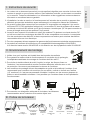
500mm
500mm
500mm 500mm
500mm
ENGLISH
I. Safety Instruction
1. The contents of this document will be updated irregularly for product version upgrade or other
reasons. Unless otherwise specied, this document only works as guide. All statements,
information and suggestions in this document do not constitute any guarantee.
2. This product can only be installed, commissioned, operated and maintained by technicians
who have carefully read and fully understood the user manual.
3. This product must only be connected with PV modules of protection class II (in accordance
with IEC 61730, application class A). PV modules with a high capacitance to ground must
only be used if their capacity does not exceed 1μF.Do not connect any sources of energy
other than PV modules to the product.
4. When exposed to sunlight, the PV modules generate dangerous high DC voltage which is
present in the DC cable conductors and live components. Touching live DC cable conductors
and live components can result in lethal injuries due to electric shock.
5. All components must remain within their permitted operating ranges at all times.
6. The product complies with Electromagnetic compatibility 2014/30/EU, Low Voltage
Directive 2014/35/EU and Radio Equipment Directive 2014/53/EU.
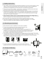
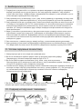
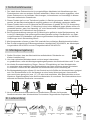
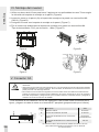
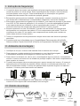
II. Mounting environment
1. Ensure that the inverter is installed out of the reach of children.
2. To ensure best operating status and prolonged service life, the
ambient temperature of the location should be ≤40°C.
3. To avoid direct sunlight, rain, snow, pooling of water on the inverter, it is
suggested to mount the inverter in places which are shaded during the majority
of the day or to install an external cover that provides shade for the inverter.
Do not place a cover directly on top of the inverter.
4. The mounting condition must be suitable for the weight and size of the inverter. The inverter
is suitable to be mounted on a solid wall that is vertical or tilted backwards (Max. 15°). It is not
recommended to install the inverter on walls made of plasterboards or similar materials.
The inverter may emit noise during operation.
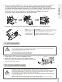
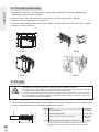
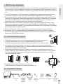
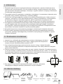
5. To ensure adequate heat dissipation, the recommended clearances
between the inverter and other objects is shown in the image to the right:
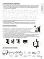
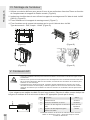
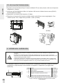
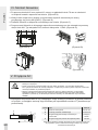
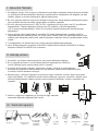
III. Scope of delivery
Inverter x1 Wall mounting
bracket x1
AC/COM
Cover
x1
AC insulation
sheet x3 Documentation
x1
Screw
accessory x1
4G/WiFi
stick x1
(optional)
DC connector
30-36KWx6
40-45KWx8
50KWx10

2
ENGLISH
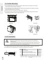
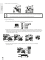
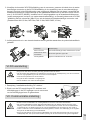
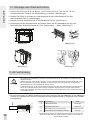
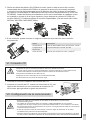
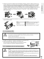
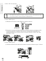
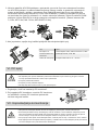
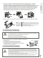
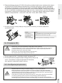
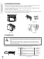
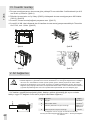
IV. Inverter Mounting
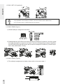
1. Use a Φ12mm bit to drill 3 holes at a depth of about 70mm according to the location
of the wall mounting bracket. (Figure A)
2. Insert wall plugs into the wall and x the wall mounting bracket to the wall by screwing
three M8 Screws (SW13). (Figure B)
3. Hang the inverter to the wall mounting bracket. (Figure C)
4. Secure the inverter to the wall mounting bracket on both sides using two M4 screws.
Screwdriver type:PH2, torque:1.6Nm. (Figure D)
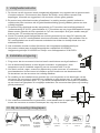
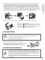
V. AC connection
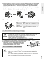
1. AC cable requirements are as follows. Strip the cable as shown in the gure, and crimp
the copper wire to the appropriate OT terminal (provided by the customer).
i
▪ All electrical installations must be done in accordance with all local and national rules.
▪ Make sure that all DC switches and AC circuit breakers have been disconnected before
establishing electrical connection. Otherwise, the high voltage within the inverter may lead
to electrical shock.
▪ In accordance with safety regulations, the inverter need be grounded rmly. When poor ground
connection (PE) occurs, the inverter will report PE grounding error. Please check and ensure
that the inverter is grounded rmly or contact AISWEI service.
。
1
2
(Figure A)
(Figure C)
(Figure B)
(Figure D)
Object Description Value
A External diameter 20-42mm
B Copper conductor cross-section 16-50mm2
CStripping length of the insulated conductors Matching
terminal
DStripping length of the cable outer sheath 130mm
The external diameter of the OT terminal shall be less than 22mm.
Please use a copper - aluminum terminal when aluminum cable
is selected.

3
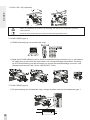
ENGLISH
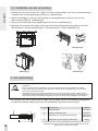
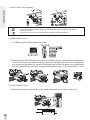
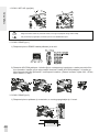
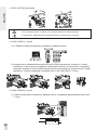
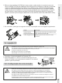
2. Remove the plastic AC/COM cover from the inverter, pass the cable through the waterproof
connector on the AC/COM cover in the wall-mounting accessories package, and retain
the appropriate sealing ring according to the wire diameter, lock the cable terminals onto
the inverter-side wiring terminals respectively (L1/L2/L3/N/PE,M8/M5), install the AC insulation
sheets onto the wiring terminals (as shown in Step 4 of the gure below), then lock the
AC/COM cover with screws (M4x10), and nally tighten the waterproof connector.
(Torque M4:1.6Nm; M5:5Nm; M8:12Nm; M63:SW65,10Nm)
3. If required, you can connect a second protective conductor as equipotential bonding.
VI. DC connection
1. Please refer to “DC Connector Installation Guide”.
2. Before DC connection, insert the DC plug connectors
with sealing plugs into DC input connectors of the inverter
to ensure protection degree.
VII. Communication setup
i
▪ Make sure PV modules have good insulation against ground.
▪ On the coldest day based on statistical records, the Max. open-circuit voltage of the PV modules
must not exceed the Max. input voltage of the inverter.
▪ Check the polarity of DC cables.
▪ Ensure that DC switch has been disconnected.
▪ Do not disconnect DC connectors under load.
Object Description
M5×12 screw Screwdriver type: PH2, torque: 2.5Nm
OT terminal lug Customer provided, type: M5
Grounding cable Copper conductor cross-section: 16-25mm2
▪ Separate communication cables from power cables and serious interference sources.
▪ The communication cables must be CAT-5E or higher-level shield cables. Pin assignment complies
with EIA/TIA 568B standard. For outdoor use, the communication cables must be UV-resistant.
The total length of communication cable cannot exceed 1000m.
▪ If only one communication cable is connected, insert a sealing plug into the unused hole of sealing
ring of the cable gland.
▪ Before connecting communication cables, ensure the protective lm or communication plate
attached to the communication opening on the inverter is sealed tightly.
i

4
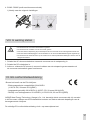
1. COM1: WiFi / 4G (optional)
2. COM2: RS485 (Type 1)
1) RS485 cable pin assignment as below.
2) Disassemble the AC/COM cover and unscrew the waterproof connector, and then guide
the cable through the connector and insert it into the corresponding terminal. Assemble
the AC/COM cover with M4 screws and screw the waterproof connector. (Screw torque:
M4:1.6Nm; M25:SW33,7.5 Nm)
3. COM2: RS485 (Type 2)
1) The cable pin assignment as below, others refer to the above type 1.
ENGLISH
A
GND
B
1
A
GND
B
▪ Only applicable to the company’s products, can’t be connected to other USB devices.
▪ The connection refers to “GPRS/ WiFi-stick User Manual”.
i
i
NOTICE

5
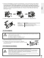
4. COM2: RS485 (Multi-machine communication)
1) Refer to the following Settings
VIII. Commissioning
1. Switch on AC circuit breaker between the inverter and the grid.
2. Switch on DC switch.
3. Please refer to the AiProfessional/Aiswei App manual for commissioning of the inverter via Wi.
When there is sucient DC power and the grid conditions are met, the inverter will start to
operate automatically.
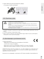
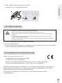
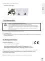
IX. EU Declaration of Conformity
Within the scope of the EU directives
- Electromagnetic compatibility 2014/30/EU
(L 96/79-106, March 29, 2014)(EMC)
- Low voltage directive 2014/35/EU (L 96/357-374, March 29, 2014)(LVD)
- Radio equipment directive 2014/53/EU (L 153/62-106, May 22, 2014)(RED)
AISWEI New Energy Technology (Jiangsu) Co., Ltd. conrms herewith that the inverters
mentioned in this document are in compliance with the fundamental requirements and other
relevant provisions of the above mentioned directives.
The entire EU Declaration of Conformity can be found at www.solplanet.net.
ENGLISH
OFF ON
i
▪ Check that the inverter is grounded reliably.
▪ Check that the ventilation condition surrounding the inverter is good.
▪ Check that the grid voltage at the point of connection of the inverter is within the permitted range.
▪ Check that the sealing plugs in DC connectors and the communication cable gland are sealed
tightly.
▪ Check that grid connection regulations and other parameter settings meet safety requirements.
i
NOTICE

6
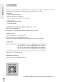
X. Contact
If you have any technical problems with our products, please contact our service.
Provide the following information to assist in providing you with the necessary
assistance:
- Inverter device type
- Inverter serial number
- Type and number of connected PV modules
- Error code
- Mounting location
- Warranty card
AISWEI New Energy Technology (Jiangsu) Co., Ltd.
Web: https://solplanet.net
Add.: No. 198 Xiangyang Road, Suzhou 215011, China
AISWEI Pty Ltd.
Hotline: +61 390 988 673
Service email: [email protected]
Add.: Level 40, 140 William Street, Melbourne VIC 3000, Australia
AISWEI B.V.
Hotline: +31 208 004 844, [email protected] (Netherlands)
+48 13 4926 109, [email protected] (Poland)
+36 465 00 384, [email protected] (Hungary)
+90 850 346 00 24, [email protected] (Turkey)
Add.: Barbara Strozzilaan 101, 5e etage, kantoornummer 5.12, 1083 HN,
Amsterdam, The Netherlands
Rest of the world
Service email: [email protected]
ENGLISH
*The manual is subject to change. The current version is available
on the website. AISWEI is not responsible for typographical or other errors.

7
500mm
500mm
500mm 500mm
500mm
СРПСКИ
I. Безбедносна упутства
1. Садржај овог документа ће се с времена на време ажурирати, када дође до надоградње
верзије производа или из других разлога. Ако није другачије наведено, овај документ
служи само као водич. Ниједна изјава, информација или предлог у овом документу се не
може сматрати гаранцијом било које врсте.
2. Овај производ могу да монтирају, пусте у рад, њиме управљају и одржавају га искључиво
техничари који су пажљиво прочитали и у потпуности разумели упутство за коришћење.
3. Овај производ може да се повеже само са фотонапонским модулима са заштитом класе II
(у складу са стандардом IEC 61730, класа примене A). Фотонапонски модули са великим
електричним капацитетом уземљења могу да се користе само ако њихов капацитет не
прелази 1μF. Немојте повезивати друге изворе енергије осим фотонапонских модула са
овим производом.
4. Када су изложени сунчевом светлу, фотонапонски модули стварају опасно висок напон
једносмерне струје која је присутна у кабловима за спровођење једносмерне струје и
компонентама под напоном. Додиривање каблова за спровођење једносмерне струје
под напоном или компонената под напоном може проузроковати фаталне повреде услед
електричног удара.
5. Све компоненте у сваком тренутку морају да буду у дозвољеним радним распонима.
6. Овај производ је усаглашен са Директивом за електромагнетску компатибилност 2014/30/
EU, Директивом за ниски напон 2014/35/EU и Директивом за радио-опрему 2014/53/EU.
II. Услови окружења за монтажу
1. Инвертор мора да се инсталира ван домашаја деце.
2. Да би се обезбедило најбоље радно стање и продужио радни век уређаја,
температура у околини инвертора мора да буде ≤ 40 °C.
3. Да би се избегло директно излагање сунцу, киши, снегу или течностима,
препоручујемо да се инвертор монтира на месту које је заштићено кровом. Немојте у
потпуности покривати горњу површину инвертора.
4. Услови монтаже морају да одговарају тежини и величини инвертора. Инвертор можеда се
монтира на чврст зид који је вертикалан или нагнут уназад (највише 15°). Не препоручује
се постављање инвертора на зидове од гипсаних плоча или сличних материјала.
Инвертор емитује звук када ради.
5. Да би се обезбедило одговарајуће одвођење топлоте препоручују се
следећа растојања између инвертора и других објеката:
III. Садржај испорученог паковања

8
СРПСКИ
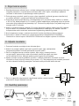
IV. Монтирање инвертора
1. Помоћу бургије Φ12 mm избушите 3 отвора дубине око 70 mm на местима која су
потребна за постављање зидног носача. (Слика А)
2. Уметните типлове у зид и причврстите зидни носач на зид помоћу три завртња M8
(SW13). (Слика Б)
3. Окачите инвертор на зидни носач. (Слика В)
4. Причврстите инвертор на зидни носач са обе стране помоћу два M4 завртња.
Врста одвијача: PH2, затезни моменат: 1,6Nm. (Слика Г)
V. Повезивање наизменичне струје
1. Захтеви за АЦ каблове су следећи. Скините изолацију са кабла као на слици и уведите
бакарне жице у одговарајући OT терминал (обезбеђује купац).
i
▪ Све електричне инсталације морају да се изведу у складу са локалним и државним
правилима.
▪ Сви прекидачи једносмерне струје и осигурачи за наизменичну струју морају да буду
искључени пре успостављања електричне везе. У супротном, високи напон у инвертору може
да проузрокује електрични удар.
▪ Инвертор мора да буде прописно уземљен, у складу са безбедносним прописима. Ако није
(заштитно уземљење – PE), инвертор ће пријавити грешку са уземљењем. Проверите и
обезбедите да инвертор буде добро уземљен или се обратите сервису компаније AISWEI.
。
1
2
Слика A
Слика B
Слика Б
Слика Г
Део Опис Вредност
A Спољни пречник 20–42mm
B Попречни пресек бакарног проводника 16–50mm2
C Дужина уклањања изолације са проводника Одговарајући
терминал
DДужина уклањања спољашњег омота кабла 130mm
Спољашњи пречник OT терминала треба да буде мањи од 22 mm.
За алуминијумски кабл употребите алуминијумско-бакарни терминал.

9
СРПСКИ
2. Уклоните пластични поклопац AC/COM са инвертора, провуците кабл кроз водоотпорни
прикључак на поклопцу AC/COM на паковању прибора за зидну монтажу и поставите
одговарајући заптивни прстен у зависности од пречника жице. Причврстите крајеве
кабла на терминале ожичења инвертора, водећи рачина о распореду (L1/L2/L3/N/PE,
M8/M5). Поставите изолационе листове за наизменичну струју на терминале ожичења
(као је приказано у 4. кораку на следећој слици). Затим причврстите поклопац AC/COM
завртњима (M4x10) и коначно причврстите водоотпорни прикључак. (Затезни моменат за
M4: 1,6 Nm; M5: 5 Nm; M8: 12 Nm; M63: SW65,10 Nm)
3. По потреби можете да повежете и други заштитни проводник као еквипотенцијалан спој.
VI. Повезивање једносмерне струје
1. Погледајте „Водич за инсталацију прикључака једносмерне струје “.
2. Пре повезивања једносмерне струје уметните утикаче за
једносмерну струју са заптивним чеповима у улазне
прикључке једносмерне струје инвертора како би се
обезбедио одговарајући степен заштите.
VII. Постављање комуникације
i
▪ Проверите да ли су фотонапонски модули добро изоловани и уземљени.
▪ Најхладнијег дана, на основу статистичких података, максималан напон отвореног кола
фотонапонских модула не сме да премаши максимални улазни напон инвертора.
▪ Проверите поларитет каблова једносмерне струје.
▪ Прекидач за једносмерну струју мора да буде искључен.
▪ Немојте да искључујете прикључке једносмерне струје док су под напоном.
Део Опис
Завртањ M5×12 Врста одвијача: PH2, затезни моменат: 2,5 Nm
Стопица за OT
терминал Обезбеђује купац, врста: M5
Кабл за уземљење Попречни пресек бакарног проводника: 16-
25mm2
▪ Одвојите комуникационе каблове од напонских каблова и већих извора интерференције.
▪ Комуникациони каблови морају да имају заштиту нивоа CAT-5E или вишег. Распоред пинова
је усаглашен са стандардом EIA/TIA 568B. Комуникациони каблови за спољну употребу
морају да буду отпорни на UV зрачење. Укупна дужина комуникационог кабла не сме да
пређе 1000
▪ Ако је повезан само један комуникациони кабл, поставите заптивни чеп у неискоришћени
заптивни прстен кабловске уводнице.
▪ Пре повезивања комуникационих каблова проверите да ли је добро причвршћен заштитни
филм или комуникациона плоча на комуникацијски отвор инвертора.
i

10
1. COM1: WiFi / 4G (опционално)
2. COM2: RS485 (тип 1)
1) Пинови кабла RS485 распоређени су како је приказано на слици.
2) Расклопите поклопац AC/COM и одврните водоотпорни прикључак, а затим провуците
кабл кроз прикључак и уметните га у одговарајући терминал. Причврстите поклопац AC/
COM помоћу завртања M4 и заврните водоотпорни прикључак. (Затезни моменат: M4:
1,6 Nm; M25: SW33, 7,5 Nm).
3. COM2: RS485 (тип 2)
1) Пинови кабла распоређени су како је приказано на слици, за друге погледајте
претходни тип 1.
СРПСКИ
A
GND
B
1
A
GND
B
▪ Користи се само за производе ове компаније, не може да се повеже са другим USB уређајима.
▪ За повезивање погледајте „Упутство за кориснике GPRS/Wi-Fi адаптера”.
i
i
NOTICE

11
4. COM2: RS485 (комуникација између више уређаја)
1) Погледајте следећа подешавања
VIII. Пуштање у рад
1. Укључите осигурач за наизменичну струју који се налази између инвертора и напонске
мреже.
2. Укључите прекидач за једносмерну струју
3. Када се достигне довољна снага једносмерне струје и када се испуне услови мреже,
инвертор ће почети аутоматски да ради
IX. Декларација о усаглашености ЕУ
У оквиру директива ЕУ:
- Директива за електромагнетску компатибилност 2014/30/EU
(L 96/79-106, 29. март 2014)(EMC)
- Директива за ниски напон 2014/35/EU (L 96/357-374, 29. март 2014)(LVD)
- Директива за радио-опрему 2014/53/EU (L 153/62-106 22. мај 2014)(RED)
AISWEI New Energy Technology (Jiangsu) Co., Ltd. овим потврђује да су инвертори који се
спомињу у овом документу усаглашени са основним захтевима и другим релевантним
одредбама наведених директива.
Комплетан текст декларације о усаглашености ЕУ можете пронаћи на www.solplanet.net.
СРПСКИ
OFF ON
i
▪ Проверите да ли је инвертор добро уземљен.
▪ Проверите да ли је добра вентилација око инвертора.
▪ Проверите да ли је напон мреже на месту повезивања инвертора у оквиру дозвољеног
распона.
▪ Проверите да ли су добро причвршћени заптивни чепови на прикључцима једносмерне
струје и на уводници комуникацијског кабла.
▪ Проверите да ли поставке свих параметара, укључујући прописе за прикључење на мрежу,
испуњавају безбедносне стандарде.
i
NOTICE

12
СРПСКИ
*The manual is subject to change. The current version is available
on the website. AISWEI is not responsible for typographical or other errors.
X. Контакт
Ако имате било каквих проблема са нашим производима, обратите се нашем сервису.
Припремите следеће информације да бисте лакше добили потребну
помоћ:
- врста инвертора
- серијски број инвертора
- врста и број фотонапонских модула
- код грешке
- место монтаже
- гарантни лист
AISWEI New Energy Technology (Jiangsu)Co., Ltd.
веб: https://solplanet.net
адреса: No. 198 Xiangyang Road, Suzhou 215011, Кина
AISWEI Pty Ltd.
дежурна линија: +61 390 988 673
е-адреса сервиса: [email protected]
адреса: Level 40, 140 William Street, Melbourne VIC 3000, Аустралија
AISWEI B.V.
дежурна линија: +31 208 004 844, [email protected] (Холандија)
+36 465 00 384, [email protected] (Мађарска)
+90 850 346 00 24, [email protected] (Турска)
адреса: Barbara Strozzilaan 101, 5e etage, kantoornummer 5.12, 1083 HN, Amsterdam,
Холандија
Остале земље
е-адреса сервиса: [email protected]

13
500mm
500mm
500mm 500mm
500mm
DANSK
I. Veiligheidsinstructie
1. De inhoud van dit document wordt onregelmatig bijgewerkt voor upgrade van de productversie
of andere redenen. Dit document dient slechts als richtlijn, tenzij anders vermeld. Alle
bepalingen, informatie en suggesties in dit document vormen geen garantie.
2. Dit product mag uitsluitend worden geïnstalleerd, in werking worden gesteld, bediend en
onderhouden door monteurs die de gebruikershandleiding grondig hebben gelezen en deze
volledig begrijpen.
3. Dit product mag uitsluitend worden aangesloten op PV-modules van beveiligingsklasse II
(overeenkomstig IE 61370, gebruiksklasse A). PV-modules met een hoge aardcapaciteit mogen
alleen worden gebruikt als hun capaciteit de 1μF niet overschrijdt. Sluit geen andere energie-
bronnen dan PV-modules op het product aan.
4. Als de PV-module wordt blootgesteld aan zonlicht genereert hij een hoge DC-spanning die
aanwezig is in de DC-voedingskabels en stroomvoerende onderdelen. Het aanraken van de
DC-voedingskabels en stroomvoerende onderdelen kan leiden tot dodelijk letsel door een
elektrische schok.
5. Alle onderdelen moeten te allen tijde binnen hun toegestane bedrijfsbereik blijven.
6. Het product voldoet aan de elektromagnetische compabiliteit 2014/30/EU,
laagspanningsrichtlijn 2014/35/EU en richtlijn voor radioapparatuur 2014/53/EU.
II. Installatie-omgeving
1. Zorg ervoor dat de omvormer buiten het bereik van kinderen wordt geïnstalleerd.
2. Om de beste bedrijfsstatus en een langere levensduur te garanderen, dient
temperatuur van de installatie-omgeving van de omvormer ≤40°C te zijn.
3. Om direct zonlicht, regen, sneeuw en plasvorming op de omvormer te voorkomen,
wordt aanbevolen de omvormer te installeren op een locatie met een beschermd dak.
De bovenkant van de omvormer niet volledig afdekken.
4. De conditie van de installatie moet geschikt zijn voor het gewicht en de afmetingen van de
omvormer. De omvormer is geschikt voor installatie op een stevige muur in verticale positie
of naar achteren gekanteld (max. 15°). Het wordt niet aanbevolen de omvormer te installeren
op een wand van gipsplaten of soortgelijke materialen. De omvormer kan tijdens zijn werking
geluid produceren.
5. Om voldoende warmteafvoer te garanderen, wordt aanbevolen de openingen
tussen de omvormer en andere voorwerpen als volgt aan te houden:
III. Bij de levering inbegrepen
Omvormer
x1
Montagebeugel
voor de muur x1
AC/COM
afdekking
x1
AC-isolatie-
plaat x3 Documentatie
x1
Schroevevtoebe-
horen x1
4G/WiFi
stick x1
(optioneel)
DC-stekker-
30-36KWx6
40-45KWx8
50KWx10

14
。
1
2
DANSK
IV. Installatie van de omvormer
1. Gebruik een bit van Φ10 mm om 3 gaten te boren met een diepte van 70 mm overeenkomstig
de plaats van de montagebeugel op de muur. (afbeelding A)
2. Steek muurpluggen in de muur en bevestig de montagebeugel op de muur met de drie
M8-schroeven (SW13). (afbeelding B)
3. Hang de omvormer op de montagebeugel voor de muur. (afbeelding C)
4. Bevestig de omvormer aan beide zijden van de muurmontagebeugel met gebruik van twee
M4-schroeven. Schroevendraaiertype: PH2 draaimoment: 1,6Nm. (afbeelding D)
V. AC-aansluiting
1. De vereisten van de AC-kabel zijn als volgt: Strip de kabel zoals in de afbeelding aangegeven
en plooi de koperen draad op de juiste OT-aansluitklem (geleverd door de klant).
i
▪ Alle elektrische installaties moeten worden uitgevoerd volgens alle plaatselijke en nationale
regelgeving.
▪ Zorg ervoor dat alle DC-schakelaars en AC-stroomonderbrekers zijn losgekoppeld voordat
er een elektrische aansluiting wordt uitgevoerd. Anders kan de hoogspanning in de omvormer
leiden tot een elektrische schok.
▪ Overeenkomstig de veiligheidsvoorschriften moet de omvormer stevig worden geaard. Bij een
gebrekkige aardverbinding (PE) zal de omvormer een PE-aardingsfout geven. Controleer en zorg
ervoor dat de omvormer stevig wordt geaard of neem contact op met de AISWEI-servicedienst.
afbeelding A
afbeelding C
afbeelding B
afbeelding D
Voorwerp Omschrijving Waarde
A Buitendiameter 20-42mm
B Koperen kabeldoorsnede 16-50mm2
C Striplengte van de geïsoleerde geleiders Bijpassende
aansluitklem
DStriplengte van de buitenste kabelmantel 130mm
De buitendiameter van de OT-aansluitklem moet kleiner zijn dan 22 mm.
Maak gebruik van een koper-aluminium aansluitklem als er wordt
gekozen voor een aluminium kabel.

15
DANSK
2. Verwijder de kunststof AC/COM-afdekking van de omvormer, passeer de kabel door de water-
bestendige connector op de AC/COM-afdekking in de verpakking van de muurbevestigings-
beugel. Houd de juiste afdichtingsring vast volgens de diameter van de draad, vergrendel de
kabelaansluitklemmen respectievelijk op de draadaansluitklemmen op de kant van de omvor-
mer (L1/L2/L3/N/PE, M8/M5), installeer de AC-isoleringsplaten op de draadaansluitklemmen
(zoals weergegeven in stap 4 van onderstaande afbeelding), en bevestig daarna de AC/COM
-afdekking met de schroeven (M4x10) en zet als laatste de waterbestendige connector vast.
(Draaimoment M4:1,6 Nm; M5:5 Nm; M8:12 Nm; M63:SW65,10 Nm)
3. Indien gewenst kunt u een tweede beschermende geleider aansluiten als potentiaalvereenin-
gskabel.
VI.DC-aansluiting
1. Raadpleeg ‘Installatiehandleiding DC-stekker’.
2. Steek voor de DC-aansluiting de DC-stekkers met
afdichtpluggen in de DC-ingangen van de omvormer
om het beveiligingsniveau te garanderen.
VII. Communicatie-instelling
i
▪ Zorg ervoor dat de PV-modules goed zijn geïsoleerd naar de aarde.
▪ Op de koudste dag gebaseerd op statistische records mag de nullastspanning van de PV-modules
de max. ingangsspanning van de omvormer niet overschrijden.
▪ Controleer de polariteit van de DC-kabels.
▪ Zorg dat de DC-schakelaar is losgekoppeld.
▪ De DC-stekkers niet onder last loskoppelen.
Voorwerp Omschrijving
M5x12-schroef Schroevendraaiertype: PH2, draaimoment: 2,5 Nm
Kabelschoen OT-a-
ansluitklem Door klant geleverd, type: M5
Aardingskabel Koperen kabeldoorsnede: 16-25mm2
▪ Scheid communicatiekabels van voedingskabels en bronnen met zware interferentie.
▪ De communicatiekabels moeten afgeschermde kabels zijn van klasse CAT-5E of hoger. Pinto-
ewijzing voldoet aan de EIA/TIA 568B-norm. Voor buitengebruik moeten de communicatiekabels
uv-bestendig zijn. De totale lengte van de communicatiekabel mag niet langer zijn dan 1000 m.
▪ Indien er maar één communicatiekabel wordt aangesloten, steekt u een afdichtplug in het ongebru-
ikte gat van de afdichtring op de kabelwartel.
▪ Zorg er ter aansluiting van de communicatiekabels voor dat de beschermende folie of het commu-
nicatieplaatje dat zich op de communicatie-opening van de omvormer bevindt, goed is afgedicht.
i

16
1. COM1: Wi / 4G (optioneel)
2. COM2: RS485 (type 1)
1) RS485 pintoewijzing van de kabel als volgt.
2) Maak de AC/COM-afdekking los en draai de waterbestendige connector los, en leid daarna
de kabel door de connector en steek deze in de overeenkomstige aansluitklem. Bevestig
de AC/COM-afdekking met M4-schroeven en schroef de waterbestendige connector vast.
(Draaimoment schroef: M4:1,6 Nm; M25:SW33,7,5 Nm)
3. COM2: RS485 (type 2)
1) De pintoewijzing van de kabel als volgt, overige verwijzen naar het bovenstaande type 1.
DANSK
A
GND
B
1
A
GND
B
▪ Alleen van toepassing op producten van het bedrijf. Kan niet worden aangesloten op andere
USB-apparaten.
▪ De aansluiting heeft betrekking op ‘Gebruikershandleiding GPRS/wi-stick’.
i
i
NOTICE

17
4. COM2: RS485 (multi-machinecommunicatie)
1) Verwijs naar de volgende instellingen
VIII. In werking stellen
1. Schakel de AC-stroomonderbreker tussen de omvormer en de netspanning in.
2. Schakel de DC-schakelaar in.
3. Indien er voldoende DC-stroom is en wordt voldaan aan de netspanningsvoorwaarden zal
de omvormer automatisch gaan functioneren.
IX. EU-conformiteitsverklaring
Binnen het bereik van de EU-richtlijnen:
- Elektromagnetische compatibiliteit 2014/30/EU
(L 96/79-106, 29 maart 2014)(EMC)
- Laagspanningsrichtlijn 2014/35/EU (L 96/357-374, 29 maart 2014)(LVD)
- Richtlijn voor radioapparatuur 2014/53/EU (L 153/62-106, 22 mei 2014)(RED)
AISWEI New Energy Technology (Jiangsu) Co., Ltd. bevestigt dat de omvormers die zijn vermeld
in dit Document voldoen aan de fundamentele vereisten en andere relevante bepalingen van de
bovengenoemde richtlijnen.
De volledige EU-conformiteitsverklaring vindt u op www.solplanet.net.
DANSK
OFF ON
i
▪ Controleer dat de omvormer betrouwbaar is geaard.
▪ Controleer dat de ventilatie rond de omvormer goed is.
▪ Controleer dat de netspanning bij het aansluitpunt van de omvormer binnen het toegestane bereik valt.
▪ Controleer dat de afdichtpluggen in de DC-stekkers en de communicatiekabelwartel goed afgedicht zijn.
▪ Controleer dat de aansluitnormen op de netstroom en andere parameterinstellingen voldoen aan de
veiligheidsvereisten.
i
NOTICE

18
DANSK
*The manual is subject to change. The current version is available
on the website. AISWEI is not responsible for typographical or other errors.
X. Contact
Neem bij technische problemen met onze producten contact op met onze servicedienst.
Geef hierbij de volgende informatie om u te voorzien van de nodige hulp:
- Type omvormersapparaat
- Serienummer omvormer
- Type en nummer van aangesloten PV-modules
- Foutcode
- Installatielocatie
- Garantiekaart
AISWEI New Energy Technology (Jiangsu) Co., Ltd.
Website: https://solplanet.net
Adres: No. 198 Xiangyang Road, Suzhou 215011, China
AISWEI Pty Ltd.
Hotline: +61 390 988 673
Service-e-mailadres: [email protected]
Adres: Level 40, 140 William Street, Melbourne VIC 3000, Australië
AISWEI B.V.
Hotline: +31 208 004 844, [email protected] (Nederland)
+36 465 00 384, [email protected] (Ungarn)
+90 850 346 00 24, [email protected] (Kalkun)
Adres: Barbara Strozzilaan 101, 5e etage, kantoornummer 5.12, 1083 HN,
Amsterdam, Nederland
Rest van de wereld
Service-e-mailadres: [email protected]
Strona się ładuje...
Strona się ładuje...
Strona się ładuje...
Strona się ładuje...
Strona się ładuje...
Strona się ładuje...
Strona się ładuje...
Strona się ładuje...
Strona się ładuje...
Strona się ładuje...
Strona się ładuje...
Strona się ładuje...
Strona się ładuje...
Strona się ładuje...
Strona się ładuje...
Strona się ładuje...
Strona się ładuje...
Strona się ładuje...
Strona się ładuje...
Strona się ładuje...
Strona się ładuje...
Strona się ładuje...
Strona się ładuje...
Strona się ładuje...
Strona się ładuje...
Strona się ładuje...
Strona się ładuje...
Strona się ładuje...
Strona się ładuje...
Strona się ładuje...
Strona się ładuje...
Strona się ładuje...
Strona się ładuje...
Strona się ładuje...
Strona się ładuje...
Strona się ładuje...
Strona się ładuje...
Strona się ładuje...
Strona się ładuje...
Strona się ładuje...
Strona się ładuje...
Strona się ładuje...
Strona się ładuje...
Strona się ładuje...
Strona się ładuje...
Strona się ładuje...
Strona się ładuje...
Strona się ładuje...
Strona się ładuje...
Strona się ładuje...
-
 1
1
-
 2
2
-
 3
3
-
 4
4
-
 5
5
-
 6
6
-
 7
7
-
 8
8
-
 9
9
-
 10
10
-
 11
11
-
 12
12
-
 13
13
-
 14
14
-
 15
15
-
 16
16
-
 17
17
-
 18
18
-
 19
19
-
 20
20
-
 21
21
-
 22
22
-
 23
23
-
 24
24
-
 25
25
-
 26
26
-
 27
27
-
 28
28
-
 29
29
-
 30
30
-
 31
31
-
 32
32
-
 33
33
-
 34
34
-
 35
35
-
 36
36
-
 37
37
-
 38
38
-
 39
39
-
 40
40
-
 41
41
-
 42
42
-
 43
43
-
 44
44
-
 45
45
-
 46
46
-
 47
47
-
 48
48
-
 49
49
-
 50
50
-
 51
51
-
 52
52
-
 53
53
-
 54
54
-
 55
55
-
 56
56
-
 57
57
-
 58
58
-
 59
59
-
 60
60
-
 61
61
-
 62
62
-
 63
63
-
 64
64
-
 65
65
-
 66
66
-
 67
67
-
 68
68
-
 69
69
-
 70
70


w innych językach
- español: solplanet ASW50K-LT-G2 Manual de usuario
- português: solplanet ASW50K-LT-G2 Manual do usuário
- français: solplanet ASW50K-LT-G2 Manuel utilisateur
- Türkçe: solplanet ASW50K-LT-G2 Kullanım kılavuzu
- Nederlands: solplanet ASW50K-LT-G2 Handleiding
Inne dokumenty
-
PNI L3000W Instrukcja obsługi
-
Dometic WAECO Perfect Power PP1004 Instrukcja obsługi
-
-
-
-
Dometic PerfectPower PP402 Instrukcja obsługi
-
-
-
-