
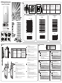
Mounting
2
1
3
Model / Lens Wide angle (H) Corridor (LLPL02) (H) Curtain (LLPL03) (H)
Numéro de Modèle
Lentille grand angle Lentille couloir (LLPL02) Lentille rideau (LLPL03)
Referencia / Modelo
Lente gran angular Lente de corredor (LLPL02) Lente cortina (LLPL03)
Codice prodotto
Lenti grandangolo Lenti corridoio (LLPL02) Lenti a tenda (LLPL03)
Códigos Lente de ângulo aberto Lente de corredor (LLPL02)
Lente de cortina (LLPL03)
Symbol / Model Soczewka szerokokątna Soczewka korytarzowa (LLPL02) Soczewka kurtynowa (LLPL03)
PIR 41502
2m-3m (6’7’’-8’10’’) 2.5m (8'2.4'') 1.5m (Typical)
EN
FR
SP
IT
PR
PL
H
PIR 41502 Curtain
(LLPL03)
1
3
0
2 4 6 8 10 1514120
2
m
5
7
4
6
Top View
Side View
2 4 6 8 10 1514120
m
2
4
6
8
10
0
2
4
6
8
10
6°
PIR 41502 Corridor Lens
(LLPL02)
2 4 6 8 10 1514120
m
2
4
6
8
10
0
2
4
6
8
10
6°
Top View
Side View
1
3
0
2 4 6 8 10 1514120
2
m
5
4
PIR 41502 Wide Angle Lens
2
4
6
8
0
2
4
6
8
2
4 6 8
10 1514120
m
90°
10
10
Top View
Side View
1
3
0
2 4 6 8 10 1514120
2
m
5
4
PIR Digital Detector
Model: PIR 4150200A
2
2
2
2
1
1
1
3
1 2 3
EN
FR
SP
IT
PR
PL
Wall mounting Corner mounting
Montage mural Montage en coin
Montaje en pared Montaje en rincón
Montaggio su parete piana Montaggio ad angolo
Montagem na parede
Montagem no canto
Mocowaniu do ściany
Mocowaniu narożnym
Swivel knockout
Miejsce mocowania uchwytu
Terminal Wiring
IT
Collegamento dei Morsetti
12VDC: Ingresso alimentazione
ALARM: Relè d’allarme NC libero da tensione
TAMPER: Relè di tamper NC libero da tensione
PR
Terminais de Conexão
12VDC: Entrada de alimentação
ALARME: Relé de contato seco NF
TAMPER: Relé de contato seco NF
PL
Podłączenie
12VDC: Zasilanie czujki
ALARM: Zaciski alarmowe NC
TAMPER: Zaciski sabotażowe NC
TAMPER
LED
ALARM
-12V+
Bornes de Conexión
12VDC: Entrada de alimentación
ALARM: Relé de Contacto Seco N.C.
TAMPER: Relé de Contacto Seco N.C.
SP
Connexion
12VDC : alimentation électrique
ALARM : contact sec NF d'alarme
TAMPER : contact sec NF d'autoprotection
FR
EN
Terminal Connection
12VDC: Power supply inputs
ALARM: NC Dry Contact switch
TAMPER: NC Dry Contact switch
LED: 12VDC activated input.
LED is enabled if it is not connected or the
12VDC is applied.
The LED is disabled if GND is applied.
LED: 12VDC activated input.
LED is enabled if it is not connected or the
12VDC is applied.
The LED is disabled if GND is applied.
LED: 12VDC activated input.
LED is enabled if it is not connected or the
12VDC is applied.
The LED is disabled if GND is applied.
LED: 12VDC activated input.
LED is enabled if it is not connected or the
12VDC is applied.
The LED is disabled if GND is applied.
LED: 12VDC activated input.
LED is enabled if it is not connected or the
12VDC is applied.
The LED is disabled if GND is applied.
LED: 12VDC activated input.
LED is enabled if it is not connected or the
12VDC is applied.
The LED is disabled if GND is applied.
EN
SP
Swivel Mounting
1. Remove the swivel entry knockout and cable entry
knockouts located on the detectors base.
2. If required, remove wires entry knockouts on the swivel.
3. Attach the swivel to the selected location on the wall or the
ceiling.
4. Attach base to swivel using the supplied plastic washer and
attaching screw.
5. Feed the cables into the detector base.
PR
FR
Swivel Mounting
1. Remove the swivel entry knockout and cable entry
knockouts located on the detectors base.
2. If required, remove wires entry knockouts on the swivel.
3. Attach the swivel to the selected location on the wall or the
ceiling.
4. Attach base to swivel using the supplied plastic washer and
attaching screw.
5. Feed the cables into the detector base.
IT
PL
Swivel Mounting
1. Remove the swivel entry knockout and cable entry
knockouts located on the detectors base.
2. If required, remove wires entry knockouts on the swivel.
3. Attach the swivel to the selected location on the wall or the
ceiling.
4. Attach base to swivel using the supplied plastic washer and
attaching screw.
5. Feed the cables into the detector base.

LEDs Display
EN
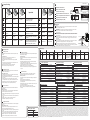
Technical Specifications
PIR 41502
Coverage
Installation height
Operating voltage 9 to 16 VDC
Current consumptio 12mA at 12V, max23.5 mA at 16V
Optical filtering White light protection, pigmented lens
Alarm and Tamper contacts 0.1A, 24V, NC
Operating temperature -10° to +50°C (+14 to 122°F)
Storage temperature -20° to + 55°C (-3 to 131°F)
Dimensions 106 x 60 x 47mm
Consommation électrique 12mA à 12V
Contacts d'alarme / d'autoprotection 0.1A, 24V, NC
Température de fonctionnement -20° à +55°C
Température de stockage -20° à +60°C
Dimensions 106 x 60 x 47mm
Filtrage Protection aux lumières blanches,
lentilles pigmentées
Spécification techniques
PIR 41502
Couverture
Hauteur d'installation
Immunité aux animaux
Tension d'alimentation 9 à 16 VCC
FR
Especificaciones Técnicas
PIR 41502
Cobertura
Altura de Instalación
Umbral Anti-Mascotas
Voltaje 9 a 16 Vcc
Consumo de corriente 12mA a 12V
Filtro óptico Protección luz blanca,
lente pigmentada
Contactos de Alarma y Tamper 0.1A, 24V, NC
Temperatura de funcionamiento -20° a +55°C
Temperatura de almacenamiento -20° a +60°C
Dimensiones 106 x 60 x 47mm
SP
Specifiche Tecniche
PIR 41502
Copertura
Altezza di Installazione
Soglia immunità animali (Pet)
Tensione nominale di alimentazione da 9 a 16 Vcc
Assorbimento massimo di corrente 12mA a 12V
Filtro Ottico Lenti pigmentate,
protezione luci bianche
Contatti d’allarme / tamper 0.1A, 24V, NC
Temperatura di funzionamento da -20° a 55°C
Temperatura di stoccaggio da -20° a 60°C
Dimensioni 106 x 60 x 47mm
IT
Filtragem Lentes pigmentadas para
Proteção contra luz branca
Temperatura operacional -20° to + 55°C
Temperatura de armazenamento -20° to + 60°C
Dimensões 106 x 60 x 47mm
Especificações Técnicas
PIR 41502
Cobertura
Altura de instalação
Limite de imunidade contra animais
Tensão de operação 9 até 16 VDC
Consumo de corrente 12mA em 12V
Contatos de alarme / Tamper NC ,24V ,0.1A
PR
Specyfikacja Techniczna
PIR 41502
Zasięg
Wysokośc instalacji
Odporność na zwierzęta
Zakres napięć zasilających 9 do 16 VDC
Podór prądu 12mA przy 12V
Filtr optyczny Filtr światła białego,
barwiona soczewka
Zaciski ALARM i TAMPER 0.1A, 24V, NC
Temperatura pracy -20° to +55°C
Temperatura składowania -20° to +60°C
Wymiary 106 x 60 x 47mm
PL
RISCO Group Limited Warranty
RISCO Group and its subsidiaries and affiliates ("Seller") warrants its products to be free from defects in materials and workmanship under normal use for 24 months from the date of production. Because Seller does not install or connect the product
and because the product may be used in conjunction with products not manufactured by the Seller, Seller cannot guarantee the performance of the security system which uses this product. Seller's obligation and liability under this warranty is
expressly limited to repairing and replacing, at Seller's option, within a reasonable time after the date of delivery, any product not meeting the specifications. Seller makes no other warranty, expressed or implied, and makes no warranty of
merchantability or of fitness for any particular purpose. In no case shall seller be liable for any consequential or incidental damages for breach of this or any other warranty, expressed or implied, or upon any other basis of liability whatsoever. Seller's
obligation under this warranty shall not include any transportation charges or costs of installation or any liability for direct, indirect, or consequential damages or delay. Seller does not represent that its product may not be compromised or
circumvented; that the product will prevent any personal injury or property loss by burglary, robbery, fire or otherwise; or that the product will in all cases provide adequate warning or protection. Buyer understands that a properly installed and
maintained alarm may only reduce the risk of burglary, robbery or fire without warning, but is not insurance or a guaranty that such event will not occur or that there will be no personal injury or property loss as a result thereof. Consequently seller
shall have no liability for any personal injury, property damage or loss based on a claim that the product fails to give warning. However, if seller is held liable, whether directly or indirectly, for any loss or damage arising under this limited warranty
or otherwise, regardless of cause or origin, seller's maximum liability shall not exceed the purchase price of the product, which shall be complete and exclusive remedy against seller. No employee or representative of Seller is authorized to change
this warranty in any way or grant any other warranty. WARNING: This product should be tested at least once a week.
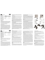
Replacing Lenses
The detector's lens is attached to the outside of the front plastic cover by
four clips.
To replace the lens:
1. Push on each one of the four clips from inside of the cover.
2. Lift the Lens from the outside of the cover.
3. Select the desired lens and make sure that the long pin is pointed
upwards.
4. Insert two clips on one side of the lens into the matching holes in the
cover and push them inside until click.
5. Repeat step 4 with the two clips on other side of the lens.
6. At the end, verify all four clips are holding the cover.
Changement de lentille
La lentille du détecteur est attachée à l'extérieur du couvercle en plastique
par 4 clips.
Pour remplacer la lentille :
1. Appuyer sur chacun des quatre clips depuis l'intérieur du couvercle.
2. Soulever la lentille depuis l'extérieur du couvercle.
3. Choisir la lentille souhaitée et s'assurer que la longue languette est vers
le haut.
4. Insérer 2 clips d'un côté de la lentille dans les trous correspondants du
couvercle et les pousser à l'intérieur jusqu'à entendre un click.
5. Répéter le point 4 avec les 2 clips de l'autre côté de la lentille.
6. A la fin, vérifier que les quatre clips tiennent bien sur le couvercle.
Cambio de las Lentes
La lente del detector está unida a la parte exterior de la cubierta frontal
de plástico mediante cuatro clips.
Para reemplazar la lente:
1. Presionar en cada uno de los cuatro clips desde el interior de la tapa.
2. Levantar la lente del exterior de la cubierta.
3. Elegir la lente deseada y asegurarse de que la marca más larga apunta
hacia arriba.
4. Insertar dos clips de uno de los lados de la lente en los agujeros
correspondientes en la tapa, y presionar hacia dentro hasta oír un clic.
5. Repetir el paso 4 con los otros dos clips del otro lado de la lente.
6. Al final, verificar que los cuatro clips están sujetos a la tapa.
Sostituzione delle lenti
Per sostituire le lenti:
EN
FR
SP
IT
Trocando as lentes
A lente do detector é pressa pelo lado de fora do detector através de 4
pinos plásticos.
Para repor a lentes:
1. Aperte cada um dos 4 pinos na parte de dentro da tampa do detector.
2. Retire a lente para o lado de fora da tampa.
3. Escolha a lente desejada e assegure-se o pino longo está preso na parte
de cima.
4. Insira os dois pinos de um lado da lente nos furos da tampa até sentir o
clique.
5. Repita o passo 4 com os dos pino do outro lado da lente.
6. Finalmente, verifique tudo para travar a tampa.
PR
Wymiana Soczewek
Soczewka czujki jest przymocowana do pokrywy przez cztery klamry.
Aby wymienić soczewkę należy wykonać następujące czynności:
Aby założyć soczewki:
PL
Replacing Lenses
7
4
LED Description
RED
Indicates
ALARM
EN
ROJO
Indica ALARMA
(detección simultánea
PIR y MW)
SP
LED Description
LED ROSSO
Indica l’allarme
(rivelazione simultanea
del canale infrarosso e di
quello microonda)
IT
LED Descrizione
O LED
VERMELHO
Indica alarme
(detecção simultânea
do IVP e MO)
PR
LED Descrição
CZERWONY
Oznacza
ALARM
PL
LED Opis
Schematic of EOL Resistors
Schéma pour Résistances EOL
(résistances de fin de ligne)
Esquema de Resistencias de Final de Línea
Schema di collegamento delle resistenze EOL
Diagrama para resistor final de linha
Rezystory parametryczne (EOL)
EN
FR
SP
IT
PR
PL
5
LED Description
ROUGE
Indique une alarme
(détection simultanée
IRP et HF)
FR
15m x 15m, 90°
2-3m
15m x 15m
da 2.0 a 2.7m
—
15m x 15m
2-2.7m
—
15m x 15m
2 -2,7 m
—
15m x 15m
2-2.7m
—
15m x 15m
2-2.7m
—
6
Walk test
Walk Test
Two minutes after applying power (warm-up period), walk test the Detector over the entire protected
area to verify proper operation of the unit.
Test de Marche
Deux minutes après avoir réalisé la mise sous tension (séquence d'initialisation), faites un test de
marche pour vérifier l'efficacité du détecteur sur la totalité de la zone protégée.
Prueba de Detección
Dos minutos después de dar alimentación (periodo de calentamiento), realice la prueba de detección
del Detector por toda el área protegida, a fin de verificar si la unidad está funcionando correctamente.
Prova Di Movimento
Dopo aver atteso un periodo di riscaldamento di 2/3 minuti dall’alimentazione, effettuare la prova di
copertura del rivelatore. Muoversi all'interno dell'area da proteggere e verificare che l'unità si attivi
correttamente.
Teste De Caminhada
Dois minutos depois ligar a alimentação (período de aquecimento), caminhe para testar o Detector
através de toda a área protegida para verificar a corretan operação da unidade.
Test
Przed rozpoczęciem testowania załóż pokrywę czujki. Włącz zasilanie czujki i odczekaj około 2
minuty, aby czujka ustabilizowała się. Przechodź po chronionej przestrzeni i obserwuj, czy dioda LED
potwierdza prawidłowe działanie czujki na całym żądanym obszarze.
Jumper Settings
Important
1 pulse 2 pulses 3 pulses
EN
FR
SP
IT
PR
PL
EN
FR
SP
IT
PR
PL
For corridor and curtain
lens use only 1 pulse.
1 impulsion 2 impulsions 3 pulses
Pour les lentilles rideau et
couloir, n'utilisez qu'une impulsion.
1 pulso 2 pulsos 3 pulses
Para la lente de pasillo o cortina usar
sólo 1 pulso.
CHIUSO APERTO 3 pulses
1 impulso 2 impulsi
Per le lenti a tenda o corridoio
utilizzare solo 1 impulso.
1 pulso 2 pulso 3 pulses
Para lente de corredor, use apenas
o pulso 1.
1 impuls 2 impulsów 3 pulses
Ważne: Dla soczewki korytarzowej i
kurtynowej licznik impulsów należy
ustawić w pozycji ON (1 impuls).
LED Enable LED Disable
LED Activée LED Désactivée
LED Activado LED Desactivado
LED Attivato LED Disattivato
LED Ativado LED Desativado
LED Aktywna LED Wyłączona
LED ON
LED
1
2
3
LED ON
LED
1
2
3
pulse 1
1
2
3
LED ON
pulse 2
1
2
3
LED ON
pulse 3
1
2
3
LED ON
EN
FR
SP
IT
PR
PL
1. Dalla parte interna del coperchio, spingere su ognuna delle quattro clip di
fissaggio.
2. Sfilare la lente dalla parte esterna del coperchio.
3. Scegliere la lente desiderata e assicurarsi che il piedino in plastica più
sporgente della lente sia rivolto verso l’alto.
4. Inserire le due clip su un lato della lente negli appositi fori del coperchio e
spingere la lente finchè non si sente uno scatto.
5. Ripetere il passo 4 per le due clip sull’altro lato della lente.
6. Alla fine, verificare che tutte e quattro le clip siano negli appositi fori del
coperchio.
1. Wciśnij każdy z czterech zaczepów soczewki znajdujących się wewnątrz
obudowy.
2. Wypchnij soczewkę na zewnątrz obudowy.
3. Weź soczewkę, którą chcesz zamontować i upewnij się, że dłuższy
wypust jest na górze.
4. Włóż dwa zaczepy z jednej strony w odpowiednie miejsca i wciśnij je tak,
aby nastąpiło ich zatrzaśnięcie.
5. Powtórz to samo z zaczepami z drugiej strony soczewki.
6. Na koniec upewnij się, że wszystkie cztery zaczepy są prawidłowo
zamknięte.
La lente del rivelatore è montata all'esterno del coperchio frontale in plastica
tramite quattro clip di fissaggio.
PANEL
DEOL
TAMPER EOL JUMPERS
NO 1K 2.2K 4.7K
RESISTOR
(FACTORY
SETTINGS)
5.6K
6.8K
ALARM EOL JUMPERS
NO 1K 2.2K 4.7K
RESISTOR
(FACTORY
SETTINGS)
5.6K
6.8K
TAMPER
LED
ALARM
-12V+
TAMPER
ALARM
Ordering part numbers
PIR 41502
LLPL02
LLPL03
Part / Model number Description
PIR Digital Detector
Corridor lens
Curtain lens
-
 1
1
-
 2
2


w innych językach
- português: Risco PIR 4150200A Manual do usuário
- français: Risco PIR 4150200A Manuel utilisateur
- English: Risco PIR 4150200A User manual
Inne dokumenty
-
 ELPLAST EOL 100 User Instruction
-
DSC LC-104-PIMW Instrukcja obsługi
-
Pyronix XDL15TT-AM Instrukcja instalacji
-
-
-
-
-
Abus FUBW50000 Instrukcja obsługi
-
Elmes Electronic PTX50 Quick Manual
-
Novus NVIP-2Q-6101/PIR/W Instrukcja obsługi
