Maico ECA 11 E Mounting And Operating Instructions
- Typ
- Mounting And Operating Instructions

Rohreinschubventilator
Duct-mounted fan
Aérateur tubulaires
ECA 11 E
Montage- und Betriebsanleitung
Mounting and Operating instructions
Instructions de montage et Mode d’emploi
www.maico-ventilatoren.com
D
GB
F
CZ
PL
H


2
Rohreinschubventilator
ECA 11 E
1. Lieferumfang
Rohreinschubventilator, 2 Schaumstoff-
bänder, Zubehörbeutel (Leitungstülle,
Zugentlastung mit 2 Schrauben, 2 Schrauben
für Motorkappe), Montage- und Betriebs-
anleitung.
2. Verwendete Symbole
2.1 Warnsymbole
GEFAHR
Lebensgefahr.
Eine Nichtbeachtung kann
zum Tod oder zu schweren
Körperverletzungen führen.
VORSICHT
Verletzungsgefahr.
Eine Nichtbeachtung kann zu
leichten bis mittleren Körper-
verletzungen führen.
ACHTUNG
Sachschäden.
Eine Nichtbeachtung kann zu
Sachschäden führen.
2.2 Sonstige Symbole
INFO-Symbol: Mit diesem
Symbol versehene Text-
passagen geben Ihnen wichtige
Informationen und Tipps.
● Aufzählungssymbol:
Liste mit wichtigen Informatio-
nen zum jeweiligen Thema.
Handlungssymbol:
Liste mit durchzuführenden
Tätigkeiten. Führen Sie die
angegebenen Anweisungen
der Reihe nach durch.
3. Produktinformationen
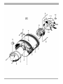
3.1 Geräteübersicht, Abb. F
1 Gehäuse
2 Anschlussklemme, 2polig
3 O-Ring
4 Motorkappe (als Ersatzteil lieferbar)
5 Leitungstülle, weiß
6 Zugentlastung
7 Schaumstoffband
8 Motor
9 Schraube
10 Motorschutzdeckel
11 Flügelrad
12 Sicherungsring
P Pfeile Förder- und Drehrichtung
T Typenschild
3.2 Produktbeschreibung
ECA 11 E-sind drehzahlsteuerbar. Der Motor
ist für den Dauerbetrieb ausgelegt. Hinter-
einanderschalten von 2 Ventilatoren ergibt
doppelte Druckstärke.
Ein/Aus erfolgt mit Lichtschalter oder
separatem Schalter (beide bauseitig).
Ventilator schaltet beim Betätigen des
Schalters sofort ein/aus.
Bei thermischer Überlastung schaltet ein
integrierter Motorüberlastungsschutz das
Gerät aus. Vor Wiederinbetriebnahme den
ECA 11 E so lange ausgeschaltet lassen,
bis Motor und Temperaturbegrenzer
abgekühlt sind. Erst dann wieder einschalten.
Impressum: © Maico Elektroapparate-Fabrik GmbH.
Deutsche Original-Betriebsanleitung.
Druckfehler, Irrtümer und technische Änderungen
vorbehalten
.
i
●
D

3
3.3 Bestimmungsgemäße
Verwendung
● Zur Belüftung oder Entlüftung, je nach
Einbaulage im Rohr.
● Für die Entlüftung von Bädern, WCs,
Abstell- und Vorratsräumen, Büros etc.
● Passend in Rohre DN 100, zum Beispiel
Wickelfalzrohr oder Wandhülse WH 100.
● Für jede Einbaulage geeignet.
3.4 Vorhersehbare Fehlanwendungen
Maico haftet nicht für Schäden durch bestim-
mungswidrigen Gebrauch. Gerät auf keinen
Fall einsetzen:
● wenn ein Berührungsschutz nach EN 294
fehlt.
● in der Nähe von brennbaren Materialien,
Flüssigkeiten oder Gasen.
● für die Förderung von Chemikalien,
aggressiven Gasen oder Dämpfen.
● in explosionsfähiger Atmosphäre.
● in Einzelentlüftungsanlagen nach
DIN 18017.
4. Technische Daten
Siehe Typenschild oder Internet.
5. Umgebungsbedingungen und
Grenzen für den Betrieb
● Zulässige Höchsttemperatur des Förder-
mediums: + 40 °C
● Bei Betrieb mit raumluftabhängigen
Feuerstätten und Einbaulage
"Entlüftung":
Unbedingt für eine ausreichende Zuluft-
nachströmung sorgen. Die maximal
zulässige Druckdifferenz pro Wohneinheit
beträgt 4 Pa.
6. Grundlegende
Sicherheitshinweise
6.1 Allgemeine Sicherheitshinweise
● Sicherheitshinweise vor Inbetriebnahme
aufmerksam durchlesen.
● Anleitung aufbewahren.
● Das Gerät darf nicht als Spielzeug
verwendet werden.
● Montage nur durch Fachkräfte zulässig.
● Elektrischer Anschluss und Reparaturen
nur durch Elektrofachkräfte zulässig.
● Die auf dem Typenschild angegebene
Schutzart ist nur gewährleistet
– bei bestimmungsgemäßem Einbau
(waagerechte Einbaulage) und
– bei ordnungsgemäßer Einführung der
Leitungen in die vorgesehene Leitungs-
tülle.
● Gerät nur an fest verlegte elektrische In-
stallation mit Leitungen vom Typ NYM-O
oder NYM-J (3 x 1,5 mm²) anschließen.
Vorrichtung zur Trennung vom Netz mit
mind. 3 mm Kontaktöffnung je Pol
erforderlich.
● Gerät nur mit auf Typenschild angegebe-
ner Spannung und Frequenz betreiben.
● Gerät nie ohne Motorkappe [4] betreiben.
● Nie ohne Schutzgitter bei freier Ansaugung
betreiben. Zum Beispiel Maico-Schutzgitter
SGR 100 montieren.
● Veränderungen und Umbauten sind nicht
zulässig und entbinden Maico von jeglicher
Gewährleistung und Haftung.
6.2 Sicheres und korrektes Verhalten
für den Betrieb
● Verletzungsgefahr. Keine Gegenstände
in den Luftkanal oder das Gerät hinein-
stecken.
● Gefahr durch sich drehendes Flügelrad.
Nicht zu nahe an das Gerät gehen, damit
Haare, Kleidung oder Schmuck nicht in das
Gerät hineingezogen werden können.
D

4
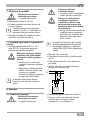
7. Montagevorbereitungen
GEFAHR
Lebensgefahr durch
Stromschlag.
Netzsicherung ausschalten.
Rohrleitung DN 100 installieren.
Elektrische Netzleitung bis zum Montageort
verlegen.
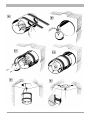
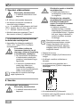
Ventilator wird außerhalb der Wand-
hülse angeschlossen, siehe Abb. C1.
Länge der Netzleitung beachten.
Beide Schaumstoffbänder [7] gemäß
Abb. A auf Gehäuse [1] kleben.
7.1 Vorbereitungen für den Betrieb
mit Drehzahlsteller
Drehzahlsteller STU 1, ST 1 oder STS 2,5
aus Maico-Zubehörprogramm verwenden.
VORSICHT
Stillstand und Funktions-
störung des Ventilators bei zu
geringer Ausgangsspannung
am Drehzahlsteller.
Hinweise in Betriebsanleitung
Drehzahlsteller beachten.
Mindestdrehzahl am Drehzahl-
steller immer so einstellen,
dass Motor nach Spannungs-
ausfall wieder anläuft.
Durch die Technik der Phasen-
anschnittsteuerung kann es zu
Brummgeräuschen kommen.
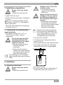
8. Montage
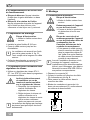
8.1 Elektrischer Anschluss
GEFAHR
Lebensgefahr durch
Stromschlag.
Netzsicherung ausschalten.
VORSICHT
Gerätebeschädigung bei
Kurzschluss.
Schutzleiter und nicht benö-
tigte Adern abschneiden und
isolieren.
VORSICHT
Kurzschlussgefahr und
Gerätebeschädigung durch
eindringendes Kondens-
wasser bei fehlerhafter
Einführung der Anschluss-
leitung.
Netzleitung ordnungsgemäß
durch Leitungstülle [5] in das
Gerät führen. Darauf achten,
dass die Leitungstülle die
Anschlussleitung dicht
umschließt.
Bei Elektroinstallation und Geräte-
montage unbedingt die einschlägigen
Vorschriften beachten, in Deutschland
insbesondere DIN VDE 0100 mit den
entsprechenden Teilen.
Motorkappe [4] abnehmen.
Zapfen der Leitungstülle [5] gemäß Abb. B
abschneiden.
Netzleitung durch die Leitungstülle führen.
Leitungen abmanteln und an Anschluss-
klemme [2] gemäß Schaltbild anschließen.
Zugentlastung [6] anbringen.
Motorkappe mit den beiden Befestigungs-
schrauben mit dem Gehäuse [1] verschrau-
ben, siehe Abb. C1.
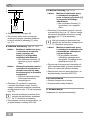
N
L
M
~
11
L
N
i
i
i
D

5
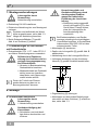
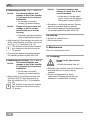
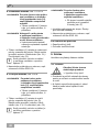
8.2 Wandmontage, Abb. C1 und C2
ACHTUNG
Funktionsstörung und Ge-
rätebeschädigung durch
streifendes Flügelrad [11]
bei fehlerhaftem Einbau.
Gehäuse [1] weder verspannt
noch gequetscht einbauen.
ACHTUNG
Kurzschlussgefahr und
Gerätebeschädigung durch
Kondenswasserbildung im
Ventilatorgehäuse.
Lüftungsleitungen fachgerecht
thermisch isolieren.
Gehäuse [1] waagerecht ausrichten und in
die Rohrleitung schieben.
Dabei die Förderrichtung beachten:
Entlüftung (Abb. C1) / Belüftung (Abb. C2)
Förder- und Drehrichtung sind auf
dem Ventilatorgehäuse durch Pfeile
"P" gekennzeichnet.
Berührungsschutz anbringen, zum Beispiel
Schutzgitter SGR 100.
8.3 Deckenmontage, Abb. D und E
ACHTUNG
Funktionsstörung und Ge-
rätebeschädigung durch
streifendes Flügelrad [11]
bei fehlerhaftem Einbau.
Gehäuse [1] weder verspannt
noch gequetscht einbauen.
Gehäuse [1] senkrecht ausrichten und in
die Rohrleitung schieben (Abb. D).
Dabei die Förderrichtung beachten:
Entlüftung (Abb. C1) / Belüftung (Abb. C2)
Förder- und Drehrichtung sind auf
dem Ventilatorgehäuse durch Pfeile
"P" gekennzeichnet.
ACHTUNG
Funktionsstörung und Ge-
rätebeschädigung bei nicht
ordnungsgemäß gesichertem
Ventilator.
Beim Deckeneinbau den
Ventilator mit 3 Schrauben
gegen Herabfallen sichern
(→ Abb. E).
Ventilator mit der Decke verschrauben.
Schrauben sind bauseitig bereitzustellen.
Berührungsschutz anbringen, zum Beispiel
Schutzgitter SGR 100.
8.4 Inbetriebnahme
Netzsicherung einschalten.
Funktionstest durchführen.
9. Instandhaltung
Das Gerät ist wartungsfrei.
10. Reinigung
GEFAHR
Lebensgefahr durch
Stromschlag.
Netzsicherung ausschalten.
Regelmäßig und sorgfältig alle Staub- und
Schmutzschichten an und innerhalb des
Luftkanals entfernen.
Zum Reinigen kein aggressives,
gesundheitsschädliches oder leicht
entflammbares Reinigungsmittel
verwenden.
i
i
D

6
11. Störungsbehebung
● Bei jeder Störung eine Elektrofachkraft
hinzuziehen.
● Reparaturen sind nur durch Elektrofach-
kräfte zulässig.
GEFAHR
Lebensgefahr, Gerät steht
unter Spannung.
Netzsicherung ausschalten.
Störung Ursache, Maßnahme
Ventilator
schaltet
nicht ein.
Keine Netzspannung.
Prüfen, ob die Netz-
sicherung ausgefallen ist.
Diese ggf. einschalten.
Ventilator
schaltet
nicht ein.
Flügelrad blockiert.
Flügelradlauf überprüfen.
Flügelrad ggf. reinigen.
Thermischer
Überlastungs-
schutz des
Motors
schaltet den
Ventilator
aus.
● Motor zu heiß.
● Ein/Aus-Schalter in
Position „Aus“ schalten.
● Warten, bis der Motor
und der Temperatur-
begrenzer abgekühlt ist.
Die Abkühlzeit kann bis
zu 10 Minuten betragen,
je nach Motorgröße und
Temperaturverhältnis.
● Ein/Aus-Schalter
in Position „Ein“ schalten.
● Besteht die Störung
weiterhin, Elektrofachkraft
hinzuziehen.
Tab.1: Störungsbehebung
12. Ersatzteile
Ersatzteil-Bestellungen:
Geben Sie generell die Druck-Nr.
dieser Anleitung 0185.0897.0006,
das Produktionsdatum (Stempel
auf dem Gehäuse) und die jeweilige
Positionsnummer in Kapitel 3.1 an.
13. Demontage
GEFAHR
Lebensgefahr durch
Stromschlag.
Netzsicherung ausschalten.
● Die Demontage ist nur durch Elektrofach-
kräfte zulässig.
14. Entsorgung
Nicht in den Restmüll.
Das Gerät enthält teils wiederver-
wertbare Stoffe, teils Substanzen,
die nicht in den Restmüll gelangen
dürfen.
Entsorgen Sie das Gerät nach Ablauf
seiner Lebensdauer nach den in Ihrem
Land geltenden Umweltrichtlinien und
Vorschriften.
i
i
D

7
Duct-mounted fan ECA 11 E
1. Scope of delivery
Duct-mounted fan, 2 foam strips, bag of
accessories (cable grommet, tension relief
with 2 screws, 2 screws for motor cover),
mounting and operating instructions.
2. Symbols used
2.1 Warning symbols
DANGER
Danger to life
Non-observance can lead to
death or serious bodily injuries.
CAUTION
Danger of injury Damage to
property Non-observance can
lead to minor or more serious
bodily injuries.
NOTICE
Damage to property
Non-observance can lead to
damage to property.
2.2 Other symbols
INFO symbol: Text passages
marked with this symbol contain
important information and tips.
●
List symbol
List containing important infor-
mation on the relevant subject.
Action symbol
List of work to be carried out.
Follow the instructions given
in the order stated.
3. Product information
3.1 Unit overview, Fig. F
1 Housing
2 Terminal, 2-pole
3 O-ring
4 Motor cover (available as spare part)
5 Cable grommet, white
6 Tension relief
7 Foam strip
8 Motor
9 Bolt
10 Motor protection cover
11 Impeller
12 Retaining ring
P Arrows for direction of air flow and
rotation
T
Rating plate
3.2 Product description
ECA 11 E fans are speed controllable.
The motor is designed for continuous
operation. Switching 2 fans on one after
another produces twice the level of pressure.
On/Off with light switch or separate switch
(both supplied by the customer). Fan
switches on/off immediately when the switch
is pressed.
In the event of thermal overload, an integra-
ted motor overload switches the unit off.
Before starting the ECA 11 E up again, leave
it switched off for long enough until the motor
and temperature limiter have cooled down.
Only then switch it back on
i
Acknowledgements:
© by Maico Elektroapparate-Fabrik GmbH.
This is a translation of the original German
Operating Instructions. We are not
responsible for mistakes or printing errors
and retain the right to make technical
modifications without
g
ivin
g
p
rior notice.
GB
●

8
3.3 Intended use
● For venting or extracting air, depending on
installation position in duct.
● For air extraction in bathrooms, WCs,
storage rooms, offices etc.
● Suitable for Ø 100 ducts e.g. folded spiral-
seam ducts or wall sleeve WH 100.
● Suitable for any installation position.
3.4 Predictable misuses
Maico is not liable for damages caused by
usage not for the intended purpose. Under
no circumstances should the unit be
used:
● if there is no protection against accidental
contact according to EN 294.
● close to flammable materials, liquids or
gasses.
● for the conveying of chemicals, aggressive
gases or vapours.
● in potentially explosive atmospheres.
● in single air extraction systems, in
Germany according to DIN 18017.
4. Technical data
See rating plate or Internet.
5. Environmental conditions and
operating limits
● Permissible maximum temperature of
medium to be conveyed + 40 °C.
● When operating with air-ventilated
fireplaces and in "air extraction"
installation position:
a sufficient fresh air supply must be
ensured. The maximum permissible
pressure difference per apartment is 4 Pa.
6. Essential safety instructions
6.1 General safety instructions
● Read the safety instructions through
carefully before starting up.
● Keep the instructions.
● The unit should not be used as a toy.
● Installation is only permitted when carried
out by trained specialists.
● Electrical connections and repairs are only
permitted when carried out by trained
specialists.
● The degree of protection stated on the
rating plate is only guaranteed
– if installation is undertaken correctly
(horizontal installation position) and
– if the cables are correctly guided into
the cable grommet provided.
● Only connect the unit to a permanent
electrical installation (max. 1.5 mm²). This
must be equipped with a mains isolation
device with contact openings of at least
3 mm at each pole.
● The unit may only be operated using the
voltage and frequency shown on the rating
plate.
● Never operate unit without motor cover [4].
● Never operate without protective grille with
free inlet. For example, fit Maico protective
grille SGR 100.
● Modifications and alterations to the unit are
not permitted and release Maico from any
guarantee obligations and liability.
6.2 Safe and correct practices during
operation
● Danger of injury Do not poke objects
into the air channel or unit.
● Danger from rotating impeller Do not get
too close to the unit, to avoid hair, clothing
or jewellery being drawn into the unit.
GB

9
7. Installation preparations
DANGER
Danger to life from electric
shock
Switch the mains fuse off.
Install Ø 100 mm ducts.
Route electrical power cable to installation
location.
Fan is connected outside the wall
sleeve, see Fig. C1. Note length of
power cable.
Stick both foam strips [7] onto housing [1]
as shown in Fig. A.
7.1 Preparations for operating with
speed controller
Use speed controller STU 1, ST 1 or
STS 2,5 from the Maico range of
accessories.
CAUTION
The fan will stop and suffer
functional problems if the
output voltage on the speed
controller is too low.
Note information in speed
controller operating
instructions.
Always set the minimum
speed on the speed controller
such that the motor starts up
again after power failure.
The technology used in the phase
angle controller may cause humming
noises.
8. Installation
8.1 Electrical connection
DANGER
Danger to life from electric
shock
Switch the mains fuse off.
CAUTION
Damage to unit in the event
of short-circuits
Cut off and insulate PE
conductor and unneeded
cable cores
CAUTION
Danger of short-circuits and
damage to unit as a result of
penetrating condensation if
the connection cable entry is
incorrect.
Guide power cable properly
through cable grommet [5]
into unit. Ensure that the cable
grommet seals off the
connection cable tightly.
Always note the relevant specifica-
tions for electrical installations and
when fitting equipment. In Germany
observe DIN VDE 0100 and the
corresponding parts in particular.
Take off motor cover [4].
Cut off journal of cable grommet [5] as
shown in Fig. B.
Guide power cable through cable grommet.
Strip cables and connect to connecting
terminal [2] as shown in wiring diagram.
Fit tension relief [6].
Screw the motor cover to the housing [1]
using both fixing screws, see fig. C1.
N
L
M
~
11
L
N
i
i
i
GB

10
8.2 Mounting on wall, Fig. C1 and C2
NOTICE
Functional problems and
damage to unit if the impeller
[11] scrapes due to incorrect
installation.
Do not twist or squash
housing [1] when installing.
NOTICE
Danger of short-circuits and
damage to unit if conden-
sation builds up in the fan
housing.
Thermally insulate ventilation
ducts in professional manner.
Align housing [1] horizontally and slide into
ducts. Note direction of air flow: Air extrac-
tion (Fig. C1) / Ventilation (Fig. C2).
The direction of air flow and rotation
are marked on the fan housing by
"P" arrows.
Fit protection against accidental contact,
for example protective grille SGR 100.
8.3 Mounting on ceiling, Fig. D and E
NOTICE
Functional problems and
damage to unit if the impeller
[11] scrapes due to incorrect
installation.
Do not twist or squash
housing [1] when installing.
Align housing [1] vertically and slide into
the ducts (Fig. D). Note direction of air
flow: Air extraction (Fig. C1) /Ventilation
(Fig. C2).
The direction of air flow and rotation
are marked on the fan housing by
"P" arrows.
NOTICE
Functional problems and
damage to unit if fans is not
secured properly.
In the case of ceiling instal-
lation, secure the fan against
falling with 3 screws (Fig E).
Screw fan to ceiling with screws. Screws
should be provided by the customer.
Fit protection against accidental contact,
for example protective grille SGR 100.
8.4 Start-up
Switch the mains fuse on.
Run function test.
9. Maintenance
The unit is maintenance-free.
10. Cleaning
DANGER
Danger to life from electric
shock
Switch the mains fuse off.
Regularly and carefully remove all layers of
dust and dirt from on and in the air
channel.
Do not use aggressive or easily
inflammable cleaning agents that are
hazardous to health when cleaning.
i
i
GB

11
11. Fault rectification
● Call on the services of a trained electrician
any time there is a fault.
● Repairs should only be carried out by a
trained electrician.
DANGER
Danger to life. Unit is powered
up.
Switch the mains fuse off.
Fault Cause, Measure
Fan doesn't
switch on.
No mains voltage.
Check whether the main
power fuse has tripped.
Switch it back on if
necessary.
Fan doesn't
switch on.
Impeller is blocked.
Check that the impeller can
turn. Clean it if necessary.
Thermal
overload
protection of
the motor
switches the
fan off.
● Motor too hot.
● Put the on/off switch to
the “off” position.
● Wait until the motor and
temperature limiter have
cooled down. Cool-down
time can be up to 10 mi-
nutes, depending on the
size of the motor and the
temperature ratio.
● Put the on/off switch to
the “on” position.
● If the fault persists, call
on the services of a
trained electrician.
Tab.1: Fault rectification
12. Spare parts
Orders for spare parts: Always state
the print no. 0185.0897.0006 of
these instructions, the production date
(stamp on housing) and the relevant
item number from chapter 3.1.
13. Dismantling
DANGER
Danger to life from electric
shock
Switch the mains fuse off.
● Dismantling should only be carried out by a
trained electrician.
14. Disposal
Do not dispose of in domestic
waste
The unit contains in part material that
can be recycled and in part substan-
ces that should not end up as
domestic waste.
Dispose of the unit once it has reached
the end of its working life according to the
regulations valid where you are.
i
i
GB

12
Aérateur tubulaires ECA 11 E
1. Éléments fournis
Un ventilateur tubulaire encastrable, 2 ban-
des en mousse, un sachet d'accessoires
(manchon de câble, décharge de traction
avec 2 vis, 2 vis pour le couvercle), notice de
montage et mode d'emploi.
2. Symboles utilisés
2.1 Symboles d'avertissement
DANGER
Danger de mort.
Le non respect peut entraîner
des blessures corporelles
graves, voire la mort.
PRUDENCE
Risque de blessure.
Dommages matériels. Le non
respect peut entraîner des
blessures corporelles légères
à moyennes.
ATTENTION
Dommages matériels.
Le non respect des symboles
d'avertissement peut entraîner
des dommages matériels.
2.2 Autres symboles
Symbole INFO : Les passages
accompagnés de ce symbole
fournissent des informations et
conseils importants.
●
Symbole d’énumération :
Liste d’informations importantes
relatives au sujet concerné.
Symbole d’action :
Liste indiquant des actions à
exécuter. Suivez les instructions
dans l'ordre indiqué.
3. Informations produit
3.1 Vue d'ensemble de l'appareil,
fig. F
1
Boîtier
2
Borne, 2 pôles
3
Joint torique
4
Couvercle (livrable comme pièce de
rechange)
5
Manchon de câble, blanc
6
Décharge de traction
7
Bande en mousse
8
Moteur
9
Vis
10
Couvercle de protection moteur
11
Hélice
12
Anneau de sûreté
P
Flèches Sens de refoulement et de rotation
T
Plaque signalétique
3.2 Description du produit
ECA 11 E à vitesse variable. Le moteur est
conçu pour un fonctionnement continu. La
mise en marche consécutive de 2 ventila-
teurs entraîne une force de pression doublée.
Marche/Arrêt avec interrupteur d'éclairage ou
interrupteur séparé (les deux à fournir par le
client). Le ventilateur se met immédiatement
en marche/arrêt en cas d'activation de
l'interrupteur.
En cas de surcharge thermique, une
protection thermique contre les surcharges
met l'appareil à l'arrêt. Avant la remise en
service de l'ECA 11 E, le laisser à l'arrêt
jusqu’à refroidissement du moteur et du
limiteur de température. Puis le remettre en
marche.
Mentions légales :
© Maico Elektroapparate-Fabrik GmbH.
Traduction du mode d'emploi d'origine en
langue allemande. Sous réserve de fautes
d'impression, d'erreurs et de modifications
techniques.
i
F
●

13
3.3 Utilisation conforme
● Pour la ventilation ou l'aération, suivant la
position dans le tuyau.
● Pour l'aération des salles de bain, WC,
locaux de rangement et de stockage,
bureaux, etc.
● S'adapte dans les tuyaux Ø 100 mm, p.e.
dans les tuyaux agrafés ou gaine murale
WH 100.
● Peut se monter dans n'importe quelle
position.
3.4 Erreurs d’application prévisibles
Maico décline toute responsabilité en cas de
dommages découlant d’une utilisation non-
conforme. Ne jamais utiliser l’appareil:
● en l'absence de protection contre les
contacts conforme à la norme EN 294.
● à proximité de matières, liquides ou gaz
inflammables.
● pour l’acheminement de produits
chimiques, de gaz ou de vapeurs toxiques.
● dans une atmosphère explosive.
● installations individuelles d'extraction d'air
conforme, pour l'Allemagne à la norme
DIN 18017.
4. Caractéristiques techniques
Se référer à la plaque signalétique ou à Internet
.
5. Conditions environnementales
et limites d'utilisation
● Température maximale admise pour le
fluide d'acheminement + 40 °C
● En cas de foyer dépendant de l'air
ambiant et de position d'installation
"extraction" :
veiller impérativement à une arrivée d'air
suffisante. La différence de pression ma-
ximale par unité d'habitation est de 4 Pa.
6. Consignes de sécurité
fondamentales
6.1 Consignes de sécurité générales
● Lire attentivement les consignes de
sécurité avant la mise en service.
● Conserver la notice.
● L’appareil ne doit pas être utilisé comme
un jouet.
● Montage exclusivement réservé aux
professionnels.
● Le branchement électrique et les
réparations sont exclusivement réservés à
des électriciens qualifiés.
● Le type de protection indiqué sur la plaque
signalétique est uniquement garanti
– en cas de montage conforme à la
destination (installation horizontale) et
– en cas d’introduction correcte des
conduites dans le manchon de câble
adéquat.
● Le ventilateur doit exclusivement être
raccordé à une installation électrique
permanente (max. 1,5 mm²). Cette
dernière doit être équipée d’un dispositif de
coupure du secteur doté d’une ouverture
de contact de 3 mm min. sur chaque pôle.
● Utiliser l'appareil exclusivement à la
tension et à la fréquence indiquées sur la
plaque signalétique.
● Ne jamais utiliser l'appareil sans
couvercle [4].
● Ne jamais utiliser sans grille de protection
en cas d'aspiration libre. Installer par
exemple une grille de protection Maico
SGR 100.
● Toute modification ou transformation de
l’appareil est interdite et dégage Maico
de toute garantie ou responsabilité.
F

14
6.2 Comportement sûr et correct lors
du fonctionnement
● Risque de blessure. Ne pas introduire
d'objet dans la gaine d'aération ou dans
l'appareil .
● Risque lié à la rotation de l’hélice.
Ne pas s’approcher trop près de l’appareil
afin d’éviter que des cheveux, des
vêtements ou des bijoux ne s’y coincent.
7. Préparation au montage
DANGER
Risque d’électrocution.
Mettre le fusible secteur hors
service.
Installer la gaine flexible Ø 100 mm.
Poser le câble secteur jusqu'au lieu
d'installation.
Le ventilateur est raccordé sur l'exté-
rieur de la gaine murale cf. fig. C1.
Tenir compte de la longueur du câble
secteur.
Coller les deux bandes en mousse [7] sur
le boîtier [1] conformément à la fig. A.
7.1 Préparation pour l'utilisation avec
régulateur de vitesse
Utiliser un régulateur de vitesse STU 1,
ST 1 ou STS 2,5 inclus dans le programme
d'accessoires Maico.
PRUDENCE
Arrêt et dysfonctionnement
du ventilateur en cas de
tension de sortie trop faible
sur le régulateur de vitesse.
Respecter les consignes du
manuel d'utilisation du
régulateur de vitesse.
Régler toujours la vitesse de
rotation minimale sur le
régulateur de vitesse de sorte
que le moteur redémarre
après une panne de courant.
La technique de réglage par hachage
de phases peut provoquer des bour-
donnements.
8. Montage
8.1 Branchement électrique
DANGER
Risque d’électrocution.
Mettre le fusible secteur hors
service.
PRUDENCE
Endommagement de l'appareil
en cas de court-circuit.
Couper et isoler le conducteur
de protection et les fils non
utilisés.
PRUDENCE
Risque de court-circuit et
endommagement de l'appareil
en cas de pénétration d'eau de
condensation lors de
l'insertion défectueuse de la
conduite de raccordement.
Faire passer le câble secteur
dans le manchon de câble [5]
dans le respect des règles de
l'art. Veiller à ce que le manchon
de câble enserre fermement le
conduit de raccordement.
Lors de l’installation électrique et du
montage de l’appareil, respecter
impérativement les directives applica-
bles et, pour l'Allemagne, plus particu-
lièrement la norme DIN VDE 0100 et
ses parties correspondantes.
Déposer le couvercle [4].
Couper le tourillon du manchon de câble
[5] conformément à la fig. B.
Faire passer le câble secteur dans le
manchon de câble.
Blinder les conduites et raccorder à la
borne de raccordement [2], conformément
au schéma de branchement.
N
L
M
~
11
L
N
i
i
i
F

15
Poser la décharge de traction [6].
Au moyen des deux vis de fixation, visser
le couvercle au boîtier [1], voir fig. C1.
8.2 Montage mural, fig. C1 et C2
ATTENTION
Dysfonctionnement et
endommagement de l'appareil
en cas de frottement de
l'hélice [11] résultant d'un
montage défectueux.
Installer le boîtier intérieur [1]
ni gauche ni coincé.
ATTENTION
Risque de court-circuit et
d’endommagement de l’ap-
pareil résultant de la formation
d’eau de condensation dans le
boîtier du ventilateur.
Procéder à une isolation
thermique des gaines d'air
dans les règles de l’art.
Aligner le boîtier [1] horizontalement et
coulisser dans la gaine flexible. Tenir
compte du sens de refoulement :
Extraction (fig. C1) / Ventilation (fig. C2).
Le sens de refoulement et le sens de
rotation sont indiqués par des flèches
"P" sur le boîtier du ventilateur.
Installer la protection contre les contacts, par
exemple une grille de protection SGR 100.
8.3 Montage au plafond, fig. D et E
ATTENTION
Dysfonctionnement et endom-
magement de l'appareil en cas
de frottement de l'hélice [11]
résultant d'un montage défec-
tueux.
Installer le boîtier intérieur [1]
ni gauche ni coincé.
Aligner le boîtier [1] verticalement et
coulisser dans la gaine flexible (fig. D).
Tenir compte du sens de refoulement :
Extraction (fig. C1) / Ventilation (fig. C2).
Le sens de refoulement et le sens
de rotation sont indiqués par des
flèches "P" sur le boîtier du ventila-
teur.
ATTENTION
Dysfonctionnement et endom-
magement de l'appareil en cas
de ventilateur non sécurisé
dans les règles de l'art.
En cas d'installation au pla-
fond, sécuriser le ventilateur
contre la chute à l'aide de
3 vis (fig. E).
Visser le ventilateur sur le couvercle. Les
vis sont à fournir par le client.
Installer la protection contre les contacts,
par exemple une grille de protection
SGR 100.
8.4 Mise en service
Enclencher le fusible secteur.
Effectuer un test de fonctionnement.
9. Maintenance
L'appareil ne nécessite aucune maintenance.
10. Nettoyage
DANGER
Risque d’électrocution.
Mettre le fusible secteur hors
service.
Enlever régulièrement tous les dépôts de
poussière et de saleté sur et à l'intérieur de
la gaine d'aération.
Ne jamais utiliser de détergents agressifs,
nocifs pour la santé ou facilement
inflammables.
i
i
F

16
11. Élimination des défauts
● Lors de tout dysfonctionnement, consulter
un électricien.
● Les réparations sont exclusivement
réservées à des électriciens qualifiés.
DANGER
Danger de mort, l'appareil est
sous tension.
Mettre le fusible secteur hors
service.
Dysfonctionnement Cause, Mesure
Le ventilateur ne
démarre pas.
Absence de tension
secteur.
Vérifier que le fusi-
ble secteur est en-
clenché. L'enclen-
cher le cas échéant.
Le ventilateur ne
démarre pas.
L'hélice est bloquée.
Contrôler la mobilité
de l'hélice. Nettoyer
l'hélice si besoin est.
La protection
thermique contre les
surcharges du
moteur met le
ventilateur à l'arrêt.
● Moteur trop chaud.
● Mettre l'interrupteur
Marche/Arrêt en
position "Arrêt".
● Attendre le refroidis-
sement du moteur et
du limiteur de tempé-
rature. Le temps de
refroidissement peut
atteindre jusqu'à
10 minutes en
fonction de la taille
du moteur et de la
température.
● Mettre l'interrupteur
Marche/Arrêt en
position "Marche".
● Si le dysfonctionne-
ment persiste, con-
tacter un électricien.
Tab. 1 : Élimination des défauts
12. Pièces de rechange
Commandes de pièces de rechange :
Veuillez systématiquement indiquer
le n° d'impression 0185.0897.0006
du présent mode d'emploi, la date de
production (tampon sur le boîtier) et
le numéro de position correspondant
du chapitre 3.1.
13. Démontage
DANGER
Risque d’électrocution.
Mettre le fusible secteur hors
service.
● Le démontage doit exclusivement être
effectué par un électricien.
14. Élimination
Ne pas jeter avec les déchets
résiduels.
L'appareil contient certaines matières
recyclables mais également d'autres
substances qui ne doivent pas être
éliminées avec les déchets résiduels.
Éliminez l'appareil arrivé en fin de vie en
respectant les règlement applicables dans
votre pays.
i
i
F

17
Zásuvný potrubní ventilátor
ECA 11 E
1. Rozsah dodávky
Zásuvný potrubní ventilátor, 2 ks pěnových
pásků, sáček s příslušenstvím (kabelová
průchodka, systém odlehčení v tahu
pomocí 2 šroubů, 2 šrouby pro víko motoru),
návod k montáži a obsluze.
2. Použité piktogramy
2.1 Výstražné piktogramy
NEBEZPEČÍ
Nebezpečí ohrožení života.
Nedodržení pokynů může
vést ke smrti nebo k těžkému
poranění.
POZOR
Nebezpečí poranění.
Nebezpečí vzniku hmotných
škod. Nedodržení pokynů může
vést ke vzniku lehkého až střed-
ně těžkého poranění.
UPOZORNĚNÍ
Nebezpečí vzniku hmotných
škod.
Nedodržení pokynů může vést
ke vzniku hmotných škod.
2.2 Ostatní piktogramy
Informační piktogram:
Text označený tímto pikto-
gramem vám poskytuje důležité
informace a tipy.
●
Odrážka:
Seznam důležitých informací na
dané téma.
Piktogram činnosti:
Seznam činností, které je nutno
provést. Uvedené pokyny
vykonejte postupně za sebou.
3. Informace o výrobku
3.1 Přehled výrobku, obr. F
1 Těleso
2 Dvoupólová svorkovnice
3 O kroužek
4 Víko motoru
(dostupné jako náhradní díl)
5 Kabelová průchodka, bílá
6 Odlehčení v tahu
7 Pěnový pásek
8 Motor
9 Šroub
10 Ochranný kryt motoru
11 Lopatkové kolo
12 Pojistný kroužek
P Šipky proudění vzduchu a otáčení
T Typový štítek
3.2 Popis výrobku
ECA 11 E - s možností regulace otáček.
Motor je navržen pro trvalý provoz. Umís-
těním dvou ventilátorů za sebou se tlak
vzduchu zdvojnásobí.
Zapínání nebo vypínání vypínačem osvětlení
nebo samostatným vypínačem (dodávka
stavby). Po stisknutí vypínače se ventilátor
okamžitě zapne, příp. vypne.
V případě tepelného přetížení vypne
integrovaná tepelná ochrana proti přetížení
ventilátor. Před opětovným zapnutím
ponechejte ventilátor ECA 11 E vypnutý do té
doby, dokud se motor a teplotní omezovač
neochladí. Až poté jej znovu zapněte.
Tiráž:
© Maico Elektroapparate-Fabrik GmbH.
Překlad originálního německého návodu k
obsluze. Tiskové chyby, omyly a technické
změn
y
v
y
hrazen
y
.
i
●
CZ

18
3.3 Užívání výrobku v souladu s jeho
určením
● Vhánění vzduchu nebo odvětrávání
v závislosti na montážní poloze v potrubí.
● Pro odvětrávání koupelen, WC, komor
a spižíren, kanceláří atd.
● Vhodný k montáži do potrubí průměru
Ø 100 mm, např. do spiro potrubí nebo
stěnového pouzdra WH 100.
● Lze provozovat v jakékoli poloze.
3.4 Možné chybné použití
Maico neručí za škody způsobené používá-
ním v rozporu s určením. Zařízení v žádném
případě nepoužívejte:
● chybí-li protidotyková ochrana podle normy
EN 294.
● v blízkosti hořlavých materiálů, kapalin
nebo plynů.
● k čerpání chemikálií, agresivních plynů
nebo par.
● ve výbušném prostředí.
● v systémech pro lokální odvětrání, v
obytných domech podle normy , v
Německu zvláště DIN 18017.
4. Technické údaje
Viz typový štítek nebo internet.
5. Okolní podmínky a omezení pro
provoz
● Nejvyšší přípustná teplota přepravovaného
média + 40 °C.
● Při provozu ohnišť s nasáváním
vzduchu z interiéru a při montážní
poloze ventilátoru pro "odvětrávání":
V každém případě zajistěte přísun
dostatečného množství vzduchu.
Maximální přípustný rozdíl tlaků v obytné
jednotce činí 4 Pa.
6. Základní bezpečnostní pokyny
6.1 Všeobecná bezpečnostní
upozornění
● Před uvedením do provozu si pozorně
přečtěte bezpečnostní upozornění.
● Návod si uschovejte.
● Zařízení nepoužívejte jako hračku.
● Montáž musí provádět způsobilá osoba.
● Elektrické připojení a opravy mohou
provádět pouze vyškolení elektrikáři.
● Druh krytí uvedený na typovém štítku je
zaručen pouze
– při stanoveném způsobu montáže
(vodorovná instalační poloha) a
– při řádném zavedení vodičů do
připravené průchodky.
● Ventilátor se smí připojovat pouze do
pevně uložené elektrické instalace
(max. 1,5 mm²). Instalace musí být
vybavena zařízením pro odpojení od sítě
se vzdáleností rozpojených kontaktů
min. 3 mm na každém pólu
● Zařízení provozujte jen s napětím a
kmitočtem sítě, které jsou uvedeny na
typovém štítku.
● Zařízení nikdy nepoužívejte bez víka
motoru [4].
● Při
nasávání z volného prostoru ventilátor
nik
dy neprovozujte bez ochranné mřížky.
Použijte např. ochrannou mřížku Maico
SGR 100.
● Změny a zásahy do zařízení nejsou povo-
leny. V opačném případě zaniká nárok na
záruku a odpovědnost společnosti Maico.
6.2 Bezpečné a správné chování při
provozu
● Nebezpečí poranění. Do vzduchového
kanálu nebo ventilátoru nezasunujte žádné
předměty.
● Nebezpečí vyplývající z rotujícího lopat-
kového kola. Nepřibližujte se do těsné
blízkosti k ventilátoru, aby nedošlo k
zachycení vlasů, částí oděvu nebo šperků.
CZ
Strona się ładuje...
Strona się ładuje...
Strona się ładuje...
Strona się ładuje...
Strona się ładuje...
Strona się ładuje...
Strona się ładuje...
Strona się ładuje...
Strona się ładuje...
Strona się ładuje...
Strona się ładuje...
Strona się ładuje...
Strona się ładuje...
Strona się ładuje...
-
 1
1
-
 2
2
-
 3
3
-
 4
4
-
 5
5
-
 6
6
-
 7
7
-
 8
8
-
 9
9
-
 10
10
-
 11
11
-
 12
12
-
 13
13
-
 14
14
-
 15
15
-
 16
16
-
 17
17
-
 18
18
-
 19
19
-
 20
20
-
 21
21
-
 22
22
-
 23
23
-
 24
24
-
 25
25
-
 26
26
-
 27
27
-
 28
28
-
 29
29
-
 30
30
-
 31
31
-
 32
32
-
 33
33
-
 34
34


Maico ECA 11 E Mounting And Operating Instructions
- Typ
- Mounting And Operating Instructions
w innych językach
- čeština: Maico ECA 11 E
- Deutsch: Maico ECA 11 E
- français: Maico ECA 11 E
- English: Maico ECA 11 E
Powiązane artykuły
-
Maico ECA 15/4 E Mounting And Operating Instructions
-
-
-
-
-
-
Inne dokumenty
-
Danfoss ECA 32 internal I/O module Instrukcja instalacji
-
Kampmann TOP unit heaters Instrukcja instalacji
-
Vents MAO1, MAO2, M1OK2 Instrukcja obsługi
-
Adler AD 7313 Instrukcja obsługi
-
Ferono FKM Series Instrukcja instalacji
-
Eglo SUSALE Instrukcja obsługi
-
 Elicent AXC Instrukcja obsługi
-
-
 Casa Fan SafeLine GreyHound TV 36-SL Mounting And Operating Manual
-
Unold 86910 Instrukcja obsługi

