EVN 15
EVN 15 P
de Fensterventilator
gb Window fan
fr Ventilateur de fenêtre
cz Okenní ventilátor
dk Vinduesventilator
es Ventilador de ventana
hu Ablakventilátor
nl Raamventilator
pl Wentylator okienny
ru Оконный вентилятор
sv Fönsterfläkt
www.maico-ventilatoren.com
Montage- und
Betriebsanleitung
Mounting and
Operating instructions
Instructions de montage
et mode d’emploi
Montážní a
provozní návod
Montage- og
driftsvejledning
Instrucciones de
montaje y manejo
Szerelési- és
üzemeltetési útmutató
Montage- en
gebruiksaanwijzing
Instrukcja montażu
i eksploatacji
Инструкция по монтажу
и эксплуатации
Monterings- och
bruksanvisning


de │ Inhaltsverzeichnis
2
Inhaltsverzeichnis
1. Lieferumfang ............................................ 2
2. Allgemeine Hinweise ................................ 2
3. Produktinformationen ............................... 2
4. Umgebungsbedingungen und Grenzen
für den Betrieb .......................................... 3
5. Technische Daten .................................... 3
6. Sicherheitshinweise ................................. 3
7. Montage ................................................... 5
8. Wartung ................................................... 6
9. Reinigung ................................................. 6
10. Störungsbehebung ................................. 7
11. Ersatzteile .............................................. 7
12. Demontage............................................. 7
13. Entsorgung ............................................. 7
14. Schaltbilder .......................................... 72
1. Lieferumfang
● Fensterventilator, Komponenten
zusammengesteckt
● Steckschlüssel, Schlüsselweite 8 (rot)
● Montage- und Betriebsanleitung
2. Allgemeine Hinweise
Lesen Sie diese Montage- und
Betriebsanleitung vor der ersten
Benutzung des Ventilators auf-
merksam durch. Folgen Sie den
Anweisungen. Bewahren Sie diese
Anleitung für einen späteren
Gebrauch gut auf.
Mit dem Smartphone
direkt zum Produkt.
2.1 Installationspersonal
Die Montage ist nur durch Fachkräfte
zulässig.
Der elektrische Anschluss darf nur von
Elektrofachkräften vorgenommen werden.
Diese besitzen eine elektrotechnische Aus-
bildung und das Wissen über die Gefahren
und Auswirkungen, die durch einen elektri-
schen Schlag erfolgen können.
2.2 Verwendete Symbole
GEFAHR
Unmittelbar drohende Gefahr,
die bei Nichtbeachtung zu
schweren Körperverletzungen
oder zum Tod führt.
VORSICHT
Möglicherweise gefährliche
Situation, die zu leichten bis
mittleren Körperverletzungen
führen könnte.
ACHTUNG
Mögliche Situation, die zu Sach-
schäden am Produkt oder seiner
Umgebung führen könnte.
INFO-Symbol für wichtige Infor-
mationen und Tipps.
●
Aufzählungssymbol für Informa-
tionen zum jeweiligen Thema.
1.
Handlungsanweisung. Führen
Sie die angegebenen Anwei-
sungen der Reihe nach durch.
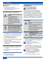
3. Produktinformationen
● EVN 15 mit selbsttätiger Außenklappe.
● EVN 15 P mit selbsttätiger Außenklappe
und ca. 1 m langer Zugkordel zur Hand-
betätigung.
● Geräte mit thermischem Überlastungs-
schutz. Dieser schaltet bei thermischer
Überlastung den Motor ab und nach
Abkühlung selbstständig wieder ein.
Impressum:
© Maico Elektroapparate-Fabrik GmbH. Deutsche
Original-Betriebsanleitung. Druckfehler, Irrtümer und
technische Änderungen vorbehalten.

3. Produktinformationen │ de
3
● Ein-/Ausschalten erfolgt bei
● EVN 15 mit bauseitig bereitzustellen-
dem separaten Schalter.
● EVN 15 P mit integriertem Zugschalter.
Zum Ein-/Ausschalten an der Zugkordel
ziehen.
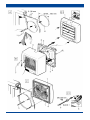
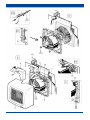
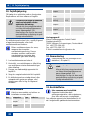
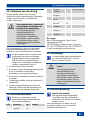
3.1 Geräteübersicht, Abb. A bis F
1 Außenklappe komplett
1.1 Lamelle
2 Flanschhülse mit
2.1 Motor und
2.2 Flügelrad
3 Innengehäuse
4 Klemmenkastendeckel
5 Schraube M5 x 50 mm
6 Haftstreifen
7 Klebepunkt
8 Sicherungsmutter
9 Steckschlüssel Schlüsselweite 8, rot
10 Zugentlastung
11 Würgenippel
12 Klemmenleiste
13 Zugschalter
S Scheiben- oder Wandausschnitt
3.2 Bestimmungsgemäße
Verwendung
● Dieses Gerät ist ausschließlich für den
Hausgebrauch und ähnliche Zwecke
vorgesehen.
● Das Gerät dient zum Entlüften von
Gaststätten, Ausstellungsräumen,
Hörsälen, Kindergärten, Krankenhäusern,
Meisterbüros und ähnlichen Räumen.
● Zulässig ist der Betrieb nur bei:
● Einbau in Flachglasfenster mit Einfach-
oder Doppelverglasung.
● Einbau in dünnen Wänden mit einer
Scheiben- oder Wanddicke von 3...30 mm.
● Einbau mit senkrechter Einbaulage.
● eingebauter Außenklappe und ange-
brachtem Innengehäuse.
3.3 Vorhersehbare Fehlanwendungen
Maico haftet nicht für Schäden durch bestim-
mungswidrigen Gebrauch. Gerät auf keinen
Fall einsetzen:
● in aufklappbaren Doppelfenstern.
● an Decken, schrägen Dächern oder
schrägen Wänden.
● in der Nähe von brennbaren Materialien,
Flüssigkeiten oder Gasen.
● für die Förderung von Chemikalien,
aggressiven Gasen oder Dämpfen.
● in explosionsfähiger Atmosphäre.
● zur Absaugung von Küchenabluft.
Außenklappe [1] auf keinen Fall demontieren.
4. Umgebungsbedingungen und
Grenzen für den Betrieb
● Zulässige Höchsttemperatur des Förder-
mediums + 40 °C.
● Bei Betrieb mit raumluftabhängigen
Feuerstätten muss für ausreichende
Zuluftnachströmung gesorgt werden.
Die maximal zulässige Druckdifferenz
pro Wohneinheit beträgt 4 Pa.
5. Technische Daten
Siehe Typenschild.
6. Sicherheitshinweise
6.1 Allgemein
● Lesen Sie diese Betriebsan-
leitung vor der Montage und
Inbetriebnahme aufmerksam
durch.
● Die Montage und der elektri-
sche Anschluss ist nur durch
Fachkräfte gemäß Kapitel 2.1
zulässig.

de │ 6. Sicherheitshinweise
4
● Bei der Elektroinstallation und
Gerätemontage sind die
einschlägigen Vorschriften,
besonders DIN VDE 0100 mit
den entsprechenden Teilen
zu beachten. In Räumen mit
Bade- oder Duscheinrichtung
z. B. Teil 701.
● Gerät nur an fest verlegte
elektrische Installation mit
Leitungen vom Typ NYM-O
oder NYM-J (0,75 - 1,5 mm²)
anschließen. Bei Geräteein-
bau in schwenkbare Fenster
geeignete, flexible Anschluss-
leitung verwenden. Außerdem
ist eine Vorrichtung zur
Trennung vom Netz mit mind.
3 mm Kontaktöffnung je Pol
anzubringen.
● Gerät nur mit auf Typenschild
angegebener Spannung und
Frequenz betreiben.
● Gerät nur komplett montiert
betreiben.
● Vor Abnehmen des Klemmen-
kastendeckels [4] das Gerät
allpolig vom Netz trennen.
● Eine ausreichende Zuluftnach-
strömung ist sicherzustellen.
● Veränderungen und Umbau-
ten am Gerät sind nicht
zulässig und entbinden den
Hersteller von jeglicher
Gewährleistung und Haftung.
6.2 Sicheres und korrektes
Verhalten für den Betrieb
Verletzungsgefahr bei
Gegenständen im Flügel-
rad. Keine Gegenstände
in das Gerät hinein-
stecken.
Verletzungsgefahr durch
sich drehendes Flügelrad.
Nicht zu nahe an das
Gerät gehen, damit
Haare, Kleidung oder
Schmuck nicht in das
Gerät hineingezogen
werden können.
● Dieses Gerät kann von
Kindern ab 8 Jahren und
darüber sowie von Personen
mit verringerten physischen,
sensorischen oder mentalen
Fähigkeiten oder Mangel an
Erfahrung und Wissen
benutzt werden, wenn sie
beaufsichtigt oder bezüglich
des sicheren Gebrauchs des
Gerätes unterwiesen wurden
und die daraus resultierenden
Gefahren verstehen.
Kinder dürfen nicht mit dem
Gerät spielen. Reinigung und
Benutzer-Wartung dürfen nicht
von Kindern ohne Beaufsich-
tigung durchgeführt werden.

7. Montage │ de
5
7. Montage, Abb. A … F
ACHTUNG
Kurzschlussgefahr, Geräte-
beschädigung. Eindringendes
Wasser bei falscher Einfüh-
rung der Netzleitung in das
Gehäuse oder unsachgemäß
eingebautem Würgenippel.
Schutzart nur bei ordnungsge-
mäßer Durchführung der Leitung
an der dafür vorgesehenen Ge-
häusedichtung (Würgenippel)
gewährleistet.
Würgenippel [11] kreisrund und
etwas kleiner als der Leitungs-
durchmesser durchbohren.
GEFAHR
Gefahr durch Schnittverletzun-
gen durch Glasbruch bei unter
Spannung stehender Scheibe.
Scheibe nur in spannungsfreiem
Zustand einbauen. Gegebenen-
falls Scheibe ausbauen und
spannungsfrei einkitten.
ACHTUNG
Außenklappe schließt nicht
korrekt, falls diese verspannt
eingebaut wird.
Außenklappe nur auf einer
ebenen Fläche montieren, um
die Klappenfunktion zu gewähr-
leisten.
Hinweise
● Ausreichend Platz zum Fensterrahmen
bzw. zur Wand oder Decke berück-
sichtigen.
● Außenklappe auf keinen Fall demontieren.
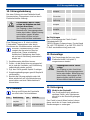
Abb. A: Montagevorbereitungen
1. Netzleitung verlegen.
2. Scheibenausschnitt [S] vom Fachmann
anbringen lassen. Bei Wand-/Holzplatten-
montage Ausschnitt [S] bohren.
3. Die Scheibe vor dem Aufkleben der
Außenklappe gründlich reinigen.
Abb. B: Innenteil auseinanderbauen
1. Dazu Innengehäuse [3] seitlich festhalten
und Flanschhülse [2] am Motor aus der
Abdeckung herausziehen.
1. Klemmenkastendeckel [4] entfernen.
Bei Wand- oder Holzplattenmontage
2. Ggf. Flanschhülse [2] an den 2 Sollbruch-
stellen [X] durchbohren ( Abb. B).
3. An der Außenklappe bei offenen Lamellen
die 4 Sollbruchstellen [Y] ( Abb. B1)
durchbohren.
Abb. C/Abb. C1: Außenklappe [1]
montieren (Außenseite)
1. Schrauben [5] in die Ösen der Außen-
klappe stecken, bis diese einrasten.
2. Schutzfolien der Klebepunkte [7]
abziehen.
3. Außenklappe im Scheibenausschnitt
ausrichten und an die Scheibe drücken.
Bei Wand- oder Holzplattenmontage
4. Außenklappe [1] mit geeignetem
Befestigungsmaterial an der Wand
bzw. Holzplatte anbringen.
Abb. D: Innenteil montieren (Innenseite)
VORSICHT
Gefahr durch Schnittverletzun-
gen durch Glasbruch bei zu fest
angezogenen Muttern.
Sicherungsmuttern [8] nur vor-
sichtig und nicht zu fest anziehen.
1. Flanschhülse [2] auf die Schrauben [5]
aufstecken, ausrichten und leicht an die
Scheibe drücken.
2. Mit beiliegendem Steckschlüssel [9] die
Sicherungsmuttern [8] festziehen
( Abb. D1 und D2).
Bei Wand- oder Holzplattenmontage
3. Flanschhülse [2] mit geeignetem
Befestigungsmaterial an der Wand
bzw. Holzplatte anbringen.

de │ 7. Montage
6
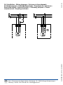
Abb. E: Gerät elektrisch anschließen,
Schaltbilder in Kapitel 14
GEFAHR
Lebensgefahr durch Strom-
schlag.
Vor Zugang zu den Anschluss-
klemmen alle Versorgungsstrom-
kreise abschalten. Netzsicherung
ausschalten, gegen Wieder-
einschalten sichern und ein
Warnschild sichtbar anbringen.
VORSICHT
Kurzschlussgefahr bei falscher
Durchführung der Netzleitung
in den Klemmenkasten.
Netzleitung ordnungsgemäß
durch Würgenippel führen und
für Zugentlastung sorgen.
1. Würgenippel [11] kreisrund durchstoßen
und in vorgesehene Bohrung einsetzen.
2. Netzleitung gemäß Schaltbild an Klem-
menleiste [12] anschließen.
3. Zugentlastung [10] anbringen.
4. Klemmenkastendeckel [4] aufsetzen und
verschrauben.
5. Innengehäuse [3] oben auf Flanschhülse
[2] einhängen und unten in die Schnapper
einrasten. Nicht verkanten.
Abb. F: Nur bei EVN 15 P-Ventilatoren
1. Zugschnur in die beiden Gehäusekerben
einlegen.
2. Innengehäuse [3] wie zuvor beschrieben
aufsetzen.
Inbetriebnahme
1. Netzsicherung einschalten.
2. Funktionstest durchführen.
8. Wartung
Das Gerät ist wartungsfrei.
Bei in schwenkbaren Fenstern
eingebauten Geräten.
Die Anschlussleitung am Übergang zum
Fensterflügel/-rahmen in regelmäßigen
Zeitabständen auf Beschädigung überprüfen.
Bei Beschädigung ist der weitere Betrieb un-
zulässig. Das Gerät ist vom Netz zu trennen
(Netzsicherung ausschalten und gegen Wie-
dereinschalten zu sichern). Anschlussleitung
durch eine Fachkraft austauschen lassen
9. Reinigung
GEFAHR
Lebensgefahr durch Strom-
schlag.
Vor Zugang zu den Anschluss-
klemmen alle Versorgungsstrom-
kreise abschalten. Netzsicherung
ausschalten, gegen Wieder-
einschalten sichern und ein
Warnschild sichtbar anbringen.
ACHTUNG
Beschädigung der Abdeckung
beim Reinigen in der Spül-
maschine.
Innengehäuse nicht in der
Spülmaschine reinigen.
1. Innengehäuse [3] unten an der rechten
und linken Seite fassen und gleichmäßig
nach vorne abziehen.
Innengehäuse [3] nicht am Innengit-
ter oder der oberen Seite abziehen.
2. Innenteile mit einem trockenen Tuch
säubern. Ggf. einen Staubsauger ver-
wenden. Zum Reinigen der Außenklappe
die Lamellen nach oben schwenken.
Zum Reinigen kein aggressives,
gesundheitsschädliches oder leicht
entflammbares Reinigungsmittel
verwenden.
3. Innengehäuse [3] anbringen ( Abb. E).

10. Störungsbehebung │ de
7
10. Störungsbehebung
Bei einer Störung ist eine Elektrofachkraft
hinzuzuziehen. Reparaturen sind nur durch
Elektrofachkräfte zulässig.
GEFAHR
Lebensgefahr durch Strom-
schlag bei Arbeiten am elek-
trischen Anschluss.
Vor Zugang zu den Anschluss-
klemmen alle Versorgungsstrom-
kreise abschalten. Netzsicherung
ausschalten, gegen Wieder-
einschalten sichern und ein
Warnschild sichtbar anbringen.
Eine Störung kann z. B. durch erhöhte
Fördermittel-Temperaturen oder durch
Blockieren des Ventilatormotors auftreten.
Wird der Ventilatormotor zu heiß,
reagiert der thermische Überlas-
tungsschutz. Dieser schaltet bei
thermischer Überlastung den Motor
ab und nach Abkühlung automatisch
wieder ein.
1. Ventilatormotor abkühlen lassen.
2. Prüfen, ob die Netzsicherung eingeschal-
tet ist und der Ventilator nach Abkühlung
selbstständig wieder anläuft.
3. Ggf. das Gerät gemäß Kapitel 9 reinigen.
4. Umgebungsbedingungen gemäß Kapitel 4
sicherstellen.
5. Besteht die Störung weiterhin oder tritt
diese wiederholt auf, die Netzsicherung
ausschalten und eine Elektrofachkraft
hinzuziehen.
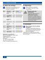
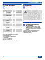
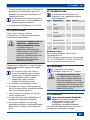
11. Ersatzteile
Bezug und Einbau der Ersatzteile
nur durch den Fachinstallateur.
Pos.
Bezeichnung
Type
Artikel-Nr.
1
Aussenklappe
komplett
15
15 P
0059.0144.9000
2
Flanschhülse
komplett
15
E059.0140.9000
2
Flanschhülse
komplett
15 P
E059.0140.9100
2.1
Motor mit
Schrauben
15
0156.0093.0001
2.2
Flügelrad mit
Spannring
15
15 P
0061.0119.0000
3
Innengehäuse
komplett
15
0059.0141.9000
3
Innengehäuse
komplett
15 P
E059.0141.9100
13
Zugschalter
komplett
15 P
E157.0794.0000
Bei Rückfragen
Maico Elektroapparate-Fabrik GmbH
Steinbeisstraße 20
78056 Villingen-Schwenningen, Deutschland
Tel. +49 7720 694 445 / Fax +49 7720 694 175
E-Mail: ersatzteilservice@maico.de
12. Demontage
Die Demontage darf nur von einer
Elektrofachkraft ( Kapitel 1)
vorgenommen werden.
GEFAHR
Lebensgefahr durch Strom-
schlag.
Vor Zugang zu den Anschluss-
klemmen alle Versorgungsstrom-
kreise abschalten. Netzsicherung
ausschalten, diese gegen Wie-
dereinschalten sichern und ein
Warnschild sichtbar anbringen.
13. Entsorgung
Nicht in den Restmüll.
Das Gerät enthält teils wiederver-
wertbare Stoffe, teils Substanzen,
die nicht in den Restmüll gelangen
dürfen.
Das Gerät ist nach Ablauf seiner Lebens-
dauer nach den in Ihrem Land geltenden
Bestimmungen zu entsorgen.

gb │ Table of contents
8
Table of contents
1. Scope of delivery ...................................... 8
2. General notes........................................... 8
3. Product information .................................. 8
4. Environmental conditions and
operating limits ......................................... 9
5. Technical data .......................................... 9
6. Safety instructions .................................... 9
7. Installation .............................................. 11
8. Maintenance........................................... 12
9. Cleaning ................................................. 12
10. Fault rectification .................................. 13
11. Spare parts........................................... 13
12. Dismantling .......................................... 13
13. Disposal ............................................... 13
14. Wiring diagrams ................................... 72
1. Scope of delivery
● Window fan, components assembled
● Socket spanner, width across flats 8, (red)
● Mounting and operating instructions
2. General notes
Read these installation and opera-
ting instructions carefully before
using the fan for the first time.
Follow the instructions. Keep these
instructions safe for use later on.
2.1 Installation staff
Installation is only permitted when carried out
by trained specialists.
Only qualified electricians are permitted to
make the electrical connections. They are
trained in electrical engineering and are
aware of the risks and consequences of an
electric shock.
2.2 Symbols used
DANGER
Direct risk of danger. Failure to
observe will result in severe
injury or death.
CAUTION
Possibly dangerous situation
which could result in minor to
moderate injuries.
NOTICE
Possible situation which could
cause damage to the product or
its surroundings.
INFO symbol indicating
important information and tips.
●
Bullet point for information on the
respective subject.
1.
Instructions. Follow the
instructions given in the order
stated.
3. Product information
● EVN 15 with airstream-operated shutter
● EVN 15 P with airstream-operated shutter
and with approx. 1 m long pull-cord for
manual operation
● Units with thermal overload protection This
switches the motor off under thermal
overload and automatically turns it on
again after cooling down.
● On/off switching takes place in
● EVN 15 with separate switch provided
by the customer
● EVN 15 P with integrated pull-switch.
Pull the pull-cord to switch the fan on/off.
Acknowledgements:
© Maico Elektroapparate-Fabrik GmbH. English
translation from the original German Operating
Instructions. We cannot be held responsible for
mistakes or printing errors and retain the right to
make technical modifications without giving prior
notice.

3. Product information │ gb
9
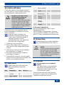
3.1 Unit Overview, Fig. A to F
1 Shutter, complete
1.1 Lamella
2 Connecting flange with
2.1 Motor and
2.2 Impeller
3 Internal housing
4 Terminal box cover
5 Screw, M5 x 50 mm
6 Adhesive strip
7 Gluing point
8 Lock nut
9 Socket spanner, width across flats 8, red
10 Tension relief
11 Self-sealing grommet
12 Terminal block
13 Pull-switch
S Window cut-out or wall cut-out
3.2 Intended use
● The unit is only intended for domestic use
and similar purposes.
● The unit serves for air extraction of
restaurants, showrooms, lecture halls,
kindergartens, hospitals, foreman's offices
and similar rooms.
● Operation is only permitted with:
● installation in flat glass windows with
single or double glazing.
● installation in thin walls with a pane or
wall thickness from 3...30 mm.
● installation in a vertical position.
● an installed shutter and fitted housing.
3.3 Foreseeable cases of misuse
Maico is not liable for damages caused by
use contrary to the intended purpose. Under
no circumstances should the unit be
used:
● in hinged double-glazed windows.
● on ceilings, sloping roofs or sloping walls.
● close to flammable materials, liquids or
gases.
● to convey chemicals, aggressive gases
or vapours.
● in explosive atmosphere.
● for air extraction of kitchen exhaust.
Never dismantle the shutter [1].
4. Environmental conditions and
operating limits
● Permissible maximum air temperature
40 °C.
● Sufficient supply air intake must be
ensured during operation with air-
ventilated fireplaces. The maximum
permitted pressure difference per living
unit is 4 Pa.
5. Technical data
See rating plate.
6. Safety instructions
6.1 General
● Read through these operating
intructions carefully before
assembly and commissioning.
● Assembly and electrical con-
nection may only be underta-
ken by trained specialists in
accordance with Chapter 2.1.
● With electrical and unit install-
lation, the relevant regulations
must be observed, particularly
DIN VDE 0100 with the cor-
responding parts. In rooms
with baths or shower units,
e. g., this would be Part 701.

gb │ 6. Safety instructions
10
● Only connect unit to perma-
nently wired electrical
installations with NYM-O
or NYM-J, (0.75 x 1.5 mm²)
cables. Use suitable, flexible
connecting cable if the unit is
installed in a swivel window.
Additionally, a mains isolation
device with contact openings
of at least 3 mm at each pole
must be installed.
● The unit may only be opera-
ted using the voltage and
frequency shown on the rating
plate.
● Only operate the unit when it
is completely installed.
● Disconnect the unit from the
power supply before removing
the terminal box cover [4].
● Ensure a sufficient supply air
intake.
● Modifications and alterations
to the unit are not permitted
and release the manufacturer
from any guarantee and
liability.
6.2 Safe and correct practices
during operation
Danger of injury in case
of objects in the impeller.
Do not insert any objects
into the unit.
Danger of injury from
rotating impeller. Do not
get too close to the fan,
to avoid hair, clothing or
jewellery being drawn into
the unit.
● This fan unit can be used by
children aged 8 and above,
and by people with reduced
physical, sensory or mental
capabilities or by persons with
insufficient experience or
knowledge provided they are
supervised by a person
responsible for their safety, or
they have been instructed
about the safe operation of
the unit and can understand
the resulting risks thereof.
Children must not play with
the unit. Cleaning and
maintenance must not be
carried out by children without
supervision.

7. Installation │ gb
11
7. Installation, Fig. A ... F
NOTICE
Danger of short-circuits, unit
damage Water will penetrate if
the power cable is incorrectly
fed into the housing or if the
self-sealing grommet is not
fitted correctly.
The degree of protection is only
guaranteed if the cables are fed
through correctly at the intended
housing seal (self-sealing
grommet).
Drill a circular hole into the self-
sealing grommet [11] that is
somewhat smaller than the cable
diameter.
DANGER
Danger of injury due to cuts
caused by glass breakage, if
the windowpane is under
stress.
Only install the windowpane so
that the glass is not under stress.
If necessary, remove the
windowpane and re-fit it so that it
is not under stress.
NOTICE
Shutter does not close
properly, if it is tensely
installed.
Only mount the shutter on a
level surface in order to
guarantee the shutter function.
Notes
● Make sure there is sufficient space to
the window frame, wall or ceiling.
● Never dismantle the shutter.
Fig. A: Installation preparation
1. Lay the power cable.
2. Get an expert to make the window cut-out
[S]. Drill the cut-out [S] in the case of wall /
wooden panel installation.
3. Clean the windowpane thoroughly before
adhesively bonding the shutter on.
Fig. B: Disassembling the inner parts
1. To do this, hold the internal housing [3]
firmly at the side and pull the connecting
flange [2] at the motor out of the cover.
2. Remove the terminal box cover [4].
In the case of wall/wooden panel installation
3. If necessary drill through the connecting
flange [2] on the 2 knockout points [X]
( Fig. B).
4. Drill through the 4 knockout points [Y]
( Fig. B1) on the shutter, with the
lamellae open.
Fig. C/Fig. C1: Installing the shutter [1]
(outside).
1. Insert the screws [5] into the eyes of the
shutter until they snap into place.
2. Remove the protective foil from the gluing
points [7].
3. Align the shutter in the window cut-out and
press it onto the pane.
In the case of wall/wooden panel installation
4. Attach the shutter [1] to the wall or wooden
panel with suitable mounting material.
Fig. D: Installing the inner parts (inside)
CAUTION
Danger of injury due to cuts
caused by glass breakage, if
the nuts have been over-
tightened.
Tighten the lock nuts [8] carefully
making sure not to over-tighten
them.
1. Attach the connecting flange [2] to the
screws [5], align it and press it gently
against the windowpane.
2. Tighten the lock nuts [8] with the supplied
socket spanner [9] ( Figs. D1 and D2).
In the case of wall/wooden panel installation
3. Attach the connecting flange [2] to the wall
or wooden panel with suitable mounting
material.

gb │ 7. Installation
12
Fig. E: Electrically connect the unit,
wiring diagram in Chapter 14
DANGER
Danger to life from electric
shock.
Prior to access to the connection
terminals switch off all supply
circuits. Switch off mains fuse,
secure against being accidentally
switched back on and position a
visible warning sign.
CAUTION
Danger of short-circuits
through incorrect feeding of
the power cable into the
terminal box.
Feed the power cable correctly
through the cable self-sealing
grommet and make sure there
is cable tension relief.
1. Make a circular hole in the self-sealing
grommet [11] and insert it into the
intended hole.
2. Connect the power cable to the terminal
block [12] as per the wiring diagram.
3. Fit tension relief [10].
4. Put the terminal box cover [4] on and
screw it into place.
5. Hang the internal housing [3] on the top of
the connecting flange [2] and clip it into
place in the safety catch. Do not twist it.
Fig. F: Only with EVN 15 P Fans:
1. Insert the pull-cord into the two housing
grooves.
2. Position the internal housing [3] as
described above.
Start-up
1. Switch the mains fuse on.
2. Carry out a function test.
8. Maintenance
The unit is maintenance-free.
With units installed in swivel
windows
Check the connection cable regularly for
signs of damage at the transfer point from
the window sash to the window frame.
If damaged, further operation of the unit is not
permitted. The unit must be disconnect from
the power supply (switch off the mains fuse
and secure it against being switched back on
again). Have the connection cable replaced
by a trained electrician.
9. Cleaning
DANGER
Danger to life from electric
shock.
Prior to access to the connection
terminals switch off all supply
circuits. Switch off mains fuse,
secure against being accidentally
switched back on and position a
visible warning sign.
NOTICE
Damage to the cover caused
by cleaning in a dishwasher.
Do not clean the internal housing
in a dishwasher.
1. Hold the internal housing [3] at the bottom,
on the right and left side and, pulling
equally on both sides, pull it forwards and
off.
Do not pull the internal housing [3]
off by the internal grille or the upper
edge.
2. Clean the internal parts with a dry cloth. If
necessary, use a vacuum cleaner. Swivel
the lamellae upwards to clean the shutter.
Do not use aggressive, harmful or
easily flammable cleaning agents for
cleaning work.
3. Attach the internal housing [3] ( Fig. E).

10. Fault rectification │ gb
13
10. Fault rectification
Call on the services of a trained electrician
any time there is a fault. Repairs should only
be carried out by a trained electrician.
DANGER
Danger to life from electric
shock when working on
electrical equipment!
Prior to access to the connection
terminals, switch off all supply
circuits. Switch off mains fuse,
secure against being accidentally
switched back on and position a
visible warning sign.
A fault can occur if, for example, the air-
stream temperature increases or if the fan
motor is blocked.
If the fan motor overheats, the
thermal overload protection reacts.
In the case of thermal overload, it
switches the motor off and
automatically turns it on again after
the motor has cooled down.
1. Let the fan motor cool down.
2. Check if the mains fuse is switched on
and if the fan starts independently after
cooling.
3. If necessary, clean the unit according to
the instructions in Chapter 9.
4. Ensure the environmental conditions
according to Chapter 4.
5. If the fault still continues or occurs again,
switch off at the mains fuse and call on the
services of a trained electrician.
11. Spare parts
Spare parts may only be sourced
from and fitted by a specialist
installer.
Item
Designation
Type
Article no.
1
Shutter,
complete
15
15 P
0059.0144.9000
2
Connecting
flange, complete
15
E059.0140.9000
2
Connecting
flange, complete
15 P
E059.0140.9100
2.1
Motor with
screws
15
0156.0093.0001
2.2
Impeller with
clamping ring
15
15 P
0061.0119.0000
3
Internal
housing,
complete
15
0059.0141.9000
3
Internal
housing,
complete
15 P
E059.0141.9100
13
Pull-switch,
complete
15 P
E157.0794.0000
In the case of questions:
Maico Elektroapparate-Fabrik GmbH
Steinbeisstraße 20,
78056 Villingen-Schwenningen, Germany
Tel. +49 (0)7720 694445 / Fax +49 (0)7720
694175, E-Mail: [email protected]
12. Dismantling
Dismantling may only be undertaken
by a trained electrician ( Chap. 1).
DANGER
Danger to life from electric
shock.
Prior to access to the connection
terminals switch off all supply
circuits. Switch off mains fuse,
secure against being accidentally
switched back on and position a
visible warning sign.
13. Disposal
Do not dispose of in domestic
waste.
The unit contains in part materials
that can be recycled and in part
substances that should not end up
in the domestic waste.
Dispose of the unit once it has reached
the end of its service life according to the
regulations valid where you are.

fr │ Sommaire
14
Sommaire
1. Volume de la fourniture .......................... 14
2. Remarques générales ............................ 14
3. Informations produit ............................... 14
4. Conditions ambiantes et limites
d'utilisation ............................................. 15
5. Caractéristiques techniques ................... 15
6. Consignes de sécurité ............................ 15
7. Montage ................................................. 17
8. Maintenance........................................... 18
9. Nettoyage ............................................... 19
10. Élimination des dysfonctionnements .... 19
11. Pièces de rechange.............................. 20
12. Démontage........................................... 20
13. Élimination ........................................... 20
14. Schémas de branchement ................... 72
1. Volume de la fourniture
● Ventilateur de fenêtre, composants
emboîtés
● Clé à pipe 8 (rouge)
● Instructions de montage et Mode d'emploi
2. Remarques générales
Lisez attentivement ce manuel
d'utilisation et de montage avant la
première utilisation du ventilateur.
Respectez les instructions.
Conservez ces instructions pour
une utilisation ultérieure.
2.1 Installateurs
Le montage est exclusivement réservé à des
professionnels.
Le branchement électrique doit exclusive-
ment être réalisé par un électricien qualifié.
Les installateurs doivent avoir une formation
électrotechnique et connaître les dangers et
les effets d'un choc électrique.
2.2 Symboles utilisés
DANGER
Danger immédiat qui, s'il n'est
pas pris en compte, entraîne de
graves blessures corporelles ou
la mort.
PRUDENCE
Situation vraisemblablement
dangereuse pouvant entraîner
des blessures corporelles de
gravité faible à moyenne.
ATTENTION
Situation pouvant entraîner des
dommages matériels du produit
ou de son environnement.
Symbole INFO pour informations
et conseils importants.
●
Symbole d'énumération
signalant des informations
relatives au sujet correspondant.
1.
Marche à suivre. Suivez les
instructions dans l'ordre indiqué.
3. Informations produit
● EVN 15 à volet extérieur automatique.
● EVN 15 P à volet extérieur automatique et
tirette de commande manuelle d'environ
1 m de long.
● Appareils à protection thermique contre
les surcharges. Cette dernière arrête le
moteur en cas de surcharge thermique
et le remet automatiquement en marche
après refroidissement.
● Mise en marche/à l'arrêt sur
● EVN 15 par commutateur séparé à
installer sur le chantier.
● EVN 15 P par commutateur à tirette
intégré. Mise en marche/à l'arrêt avec
la tirette.
Mentions légales :
© Maico Elektroapparate-Fabrik GmbH. Traduction du
mode d'emploi d'origine. Sous réserve de fautes
d’impression, d’erreurs et de modifications techniques.

3. Informations produit │ fr
15
3.1 Aperçu de l'appareil, fig. A à F
1 Volet extérieur complet
1.1 Lamelle
2 Manchon d'assemblage avec
2.1 moteur et
2.2 hélice
3 Boîtier intérieur
4 Couvercle du bornier
5 Vis M5 x 50 mm
6 Bandelette adhésive
7 Point de colle
8 Écrou de sûreté
9 Clé à pipe 8, rouge
10 Décharge de traction
11 Raccord à vis
12 Réglette de bornier
13 Commutateur à tirette
S Découpe dans vitre ou mur
3.2 Utilisation conforme
● Cet appareil est exclusivement réservé
à l'usage domestique et similaire.
● Cet appareil sert à la ventilation de
restaurants, salles d'exposition,
amphithéâtres, jardins d'enfants, hôpitaux,
bureaux de contremaîtres et similaires.
● Le fonctionnement est uniquement
autorisé aux conditions suivantes :
● Montage dans fenêtre à verre laminé
à vitrage simple ou double
● Montage dans murs minces avec une
épaisseur de verre ou de mur comprise
entre 3 et 30 mm.
● Montage en position verticale.
● Volet extérieur intégré et boîtier intérieur
monté.
3.3 Erreurs d'application prévisibles
Maico décline toute responsabilité en cas de
dommages résultant d'une utilisation non
conforme. Ne jamais utiliser l'appareil :
● dans des doubles fenêtres ouvrables.
● sur des plafonds ou des toits ou murs
inclinés.
● à proximité de matériaux, de liquides
ou gaz inflammables.
● pour l'acheminement de produits chimi-
ques, de gaz ou de vapeurs agressifs.
● dans des atmosphères explosives.
● pour aspirer l'air vicié des cuisines.
Ne jamais démonter le volet extérieur [1].
4. Conditions ambiantes et limites
d'utilisation
● Température maximale admise pour le
fluide d'acheminement + 40 °C.
● Lors d'une utilisation avec des foyers
dépendants de l'air ambiant, il faut veiller
à une arrivée d'air suffisante.
La différence de pression maximale par
unité d'habitation est de 4 Pa.
5. Caractéristiques techniques
Voir plaque signalétique.
6. Consignes de sécurité
6.1 Généralités
● Avant le montage et la mise
en service, prière de lire
attentivement le présent
Mode d'emploi.
● Montage et branchement
électrique doivent exclu-
sivement être effectués par
des spécialistes selon les
instructions du Chapitre 2.1.

fr │ 6. Consignes de sécurité
16
● Lors de l'installation électrique
et le montage de l'appareil, il
convient de respecter les
règles de l'art et plus particu-
lièrement la norme DIN VDE
0100 avec ses parties corres-
pondantes. Dans des locaux
équipés d’une baignoire ou
d’une douche, par ex.
Partie 701.
● Brancher exclusivement
l'appareil sur une installation
électrique permanente avec
des conduites de type, NYM-O
ou NYM-J (0,75 - 1,5 mm²).
Lors de l’installation de
l’appareil dans des fenêtres
pivotantes utiliser un câble
souple approprié pour le
branchement. Par ailleurs,
prévoir un dispositif de
coupure du secteur avec une
ouverture de contact d'au
moins 3 mm par pôle.
● Utiliser exclusivement
l'appareil à la tension et à la
fréquence indiquées sur la
plaque signalétique.
● N'utiliser l'appareil qu'après
son montage complet.
● Avant d’enlever le couvercle
du bornier [4], couper
l’appareil sur tous les pôles
du secteur.
● Assurer une affluence d'air
suffisante.
● Les modifications et transfor-
mations apportées sur l'appa-
reil sont rigoureusement
interdites et dégagent le
fabricant de toute respon-
sabilité et garantie.
6.2 Comportement sûr et cor-
rect lors du fonctionnement
Risque de blessure en
présence d'objets dans
l'hélice. Ne jamais
enfoncer d’objet dans
l’appareil.
Risque de blessure par
rotation de l'hélice. Ne
pas s'approcher trop près
de l'appareil afin d'éviter
que les cheveux, les
vêtements ou les bijoux
ne soient happés.
● Cet appareil peut être utilisé
par des enfants de 8 ans et
plus, ainsi que par des
personnes à capacités
physiques, sensorielles ou
mentales amoindries, ou
encore manquant d'expéri-
ence et de connaissances,
dans la mesure où elles sont
surveillées, ont reçu les
instructions nécessaires à un
emploi en toute sécurité de
l'appareil, et ont été mises en
garde contre les dangers qu'il
représente.

6. Consignes de sécurité │ fr
17
Les enfants ne doivent pas
jouer avec l'appareil. Les
enfants sans surveillance ne
doivent pas nettoyer l'appareil
ou procéder à des travaux
d'entretien revenant à
l'utilisateur.
7. Montage, fig. A … F
ATTENTION
Risque de court-circuit,
endommagement de
l'appareil. Risque de
pénétration d’eau en cas de
mauvaise insertion du
câble secteur dans le
boîtier ou de montage
incorrect du raccord à vis.
Type de protection
uniquement garanti lors du
placement du câble à travers
le joint du boîtier (raccord à
vis) prévu à cet effet.
Percer le raccord à vis [11]
d’un trou circulaire et d’un
diamètre légèrement plus
petit que celui du câble.
DANGER
Danger de coupures
provoquées par le bris
d’une vitre sous contrainte.
Installer la vitre uniquement
dans un état sans
contraintes. Le cas échéant,
démonter la vitre et la
mastiquer sans contraintes.
ATTENTION
Le volet extérieur ne ferme
pas correctement lorsqu'il
a été monté sous
contrainte.
Monter le volet extérieur
uniquement sur une surface
plane afin de garantir la
fonction volet.
Remarques
● Prévoir suffisamment d'espace jusqu’au
cadre de fenêtre, au mur ou au plafond.
● Ne démonter le volet extérieur en aucun
cas.
Fig. A : Préparatifs de montage
6. Tirer le câble secteur.
7. Faire placer la découpe de vitre [S] par un
professionnel. En cas de montage mural
ou sur une plaque de bois, percer la
découpe [S].
8. Nettoyer rigoureusement la vitre avant
d’y coller le volet extérieur.
Fig. B : Démontage de la partie intérieure
1. Pour ce faire, maintenir le boîtier intérieur
[3] sur les côtés et retirer le manchon
d'assemblage [2] sur le moteur du capot.
2. Retirer le couvercle du bornier [4].
Montage mural ou sur une plaque en bois
3. Le cas échéant, percer le manchon
d'assemblage [2] aux 2 points destinés
à la rupture [X] ( fig. B).
4. Percer les 4 points destinés à la rupture
[Y] (fig. B1) sur le volet extérieur, avec
les lamelles ouvertes.
Fig. C/Fig. C1 : Monter le volet extérieur
[1] (côté extérieur).
1. Insérer les vis [5] dans les œillets du volet
extérieur, jusqu'à ce qu'elles
s'encliquètent.
2. Retirer les films protecteurs des points de
colle [7].
3. Aligner le volet extérieur dans la découpe
de vitre et l’appuyer contre la vitre.
Montage mural ou sur une plaque en bois
4. Fixer le volet extérieur [1] avec du matériel
de fixation approprié sur le mur ou la
plaque en bois.

fr │ 7. Montage
18
Fig. D : Monter la partie intérieure (côté
intérieur)
PRUDENCE
Danger de coupures
provoquées par le bris d’une
vitre lorsque les écrous sont
serrés trop fermement.
Ne serrer les écrous de sûreté
[8] que doucement et pas trop
fermement.
1. Poser le manchon d'assemblage [2] sur
les vis [5], l’aligner et le presser
légèrement contre la vitre.
2. Serrer les écrous de sûreté [8] avec la clé
à pipe [9] fournie (fig. D1 et D2).
Montage mural ou sur une plaque en bois
3. Fixer le manchon d'assemblage [2] avec
du matériel de fixation approprié sur le
mur ou la plaque en bois.
Fig. E : Branchement électrique de
l’appareil, Schémas de branchement
au Chapitre 14
DANGER
Danger de mort par
électrocution.
Avant d'accéder aux bornes,
couper tous les circuits
d'alimentation électrique.
Désactiver le fusible secteur,
sécuriser contre toute remise
en service intempestive et
apposer un panneau
d'avertissement de manière
bien visible.
PRUDENCE
Risque de court-circuit en
cas de mauvaise insertion du
câble secteur dans le
bornier.
Guider correctement le câble
secteur à travers le raccord à
vis et garantir la décharge de
traction.
1. Percer le raccord à vis [11] d’un trou
circulaire et l’insérer dans le forage prévu.
2. Brancher le câble secteur sur la réglette
de bornier [12] selon le schéma de
branchement.
3. Poser la décharge de traction [10].
4. Poser le couvercle du bornier [4] et
le visser.
5. Accrocher le boîtier intérieur [3] en haut
sur le manchon d'assemblage [2] et
l’enclencher en bas dans les cliquets.
Ne pas gauchir.
Fig. F : Uniquement pour les ventilateurs
EVN 15 P
1. Insérer la tirette dans les deux encoches
du boîtier.
2. Poser le boîtier intérieur [3] comme décrit
ci-dessus.
Mise en service
1. Activer le fusible secteur.
2. Effectuer un test de fonctionnement.
8. Maintenance
L'appareil ne nécessite aucune maintenance.
Pour les ventilateurs sur fenêtres
pivotantes.
Contrôler à intervalles réguliers le bon état du
câble de connexion au niveau du raccord
battant de fenêtre/cadre de fenêtre.
En cas d’endommagement, il est interdit de
faire fonctionner l'appareil. L'appareil doit être
coupé du secteur (désactiver le fusible
secteur et sécuriser contre toute remise en
service intempestive). Faire remplacer le
câble de connexion par un professionnel.
Strona się ładuje...
Strona się ładuje...
Strona się ładuje...
Strona się ładuje...
Strona się ładuje...
Strona się ładuje...
Strona się ładuje...
Strona się ładuje...
Strona się ładuje...
Strona się ładuje...
Strona się ładuje...
Strona się ładuje...
Strona się ładuje...
Strona się ładuje...
Strona się ładuje...
Strona się ładuje...
Strona się ładuje...
Strona się ładuje...
Strona się ładuje...
Strona się ładuje...
Strona się ładuje...
Strona się ładuje...
Strona się ładuje...
Strona się ładuje...
Strona się ładuje...
Strona się ładuje...
Strona się ładuje...
Strona się ładuje...
Strona się ładuje...
Strona się ładuje...
Strona się ładuje...
Strona się ładuje...
Strona się ładuje...
Strona się ładuje...
Strona się ładuje...
Strona się ładuje...
Strona się ładuje...
Strona się ładuje...
Strona się ładuje...
Strona się ładuje...
Strona się ładuje...
Strona się ładuje...
Strona się ładuje...
Strona się ładuje...
Strona się ładuje...
Strona się ładuje...
Strona się ładuje...
Strona się ładuje...
Strona się ładuje...
Strona się ładuje...
Strona się ładuje...
Strona się ładuje...
Strona się ładuje...
Strona się ładuje...
-
 1
1
-
 2
2
-
 3
3
-
 4
4
-
 5
5
-
 6
6
-
 7
7
-
 8
8
-
 9
9
-
 10
10
-
 11
11
-
 12
12
-
 13
13
-
 14
14
-
 15
15
-
 16
16
-
 17
17
-
 18
18
-
 19
19
-
 20
20
-
 21
21
-
 22
22
-
 23
23
-
 24
24
-
 25
25
-
 26
26
-
 27
27
-
 28
28
-
 29
29
-
 30
30
-
 31
31
-
 32
32
-
 33
33
-
 34
34
-
 35
35
-
 36
36
-
 37
37
-
 38
38
-
 39
39
-
 40
40
-
 41
41
-
 42
42
-
 43
43
-
 44
44
-
 45
45
-
 46
46
-
 47
47
-
 48
48
-
 49
49
-
 50
50
-
 51
51
-
 52
52
-
 53
53
-
 54
54
-
 55
55
-
 56
56
-
 57
57
-
 58
58
-
 59
59
-
 60
60
-
 61
61
-
 62
62
-
 63
63
-
 64
64
-
 65
65
-
 66
66
-
 67
67
-
 68
68
-
 69
69
-
 70
70
-
 71
71
-
 72
72
-
 73
73
-
 74
74


Maico EVN 15 P Mounting And Operating Instructions
- Typ
- Mounting And Operating Instructions
- Niniejsza instrukcja jest również odpowiednia dla
w innych językach
- čeština: Maico EVN 15 P
- español: Maico EVN 15 P
- Deutsch: Maico EVN 15 P
- svenska: Maico EVN 15 P
- français: Maico EVN 15 P
- English: Maico EVN 15 P
- dansk: Maico EVN 15 P
- русский: Maico EVN 15 P
- Nederlands: Maico EVN 15 P
Powiązane artykuły
-
Maico EVN 15 P Assembly Instructions
-
-
-
-
-
-