
Control unit 1-10 V, 4-gang
Control unit 1-10 V, 4-gang
Art. No. : 2194REGHM
Operating instructions
1 Safety instructions
Electrical devices may only be mounted and connected by electrically skilled
persons.
Serious injuries, fire or property damage possible. Please read and follow manual fully.
Danger of electric shock. Device is not suitable for disconnection from supply voltage.
Danger of electric shock. The 1...10 V control voltage is a functional extra-low voltage
(FELV), and can be connected to mains potential. On installing, ensure safe separation to
SELV/PELV systems. In order to disconnect the connected luminaires, disconnect both
the mains voltage and control voltage circuits.
These instructions are an integral part of the product, and must remain with the end
customer.
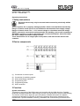
2 Device components
Figure 1
(1) Connection for control inputs
(2) Connection for switching outputs
(3) Slide switch/Status indication
(4) Programming LED
(5) Programming button
(6) KNX connection
3 Function
System information
This device is a product of the KNX system and complies with the KNX directives. Detailed
technical knowledge obtained in KNX training courses is a prerequisite to proper understanding.
The function of this device depends upon the software. Detailed information on loadable
software and attainable functionality as well as the software itself can be obtained from the
manufacturer´s product database. Planning, installation and commissioning of the device are
1/5
82594903
j0082594903
28.06.2016

carried out with the aid of KNX-certified software. The latest versions of product database and
the technical descriptions are available on our website.
Intended use
- Switching and brightness setting for lamps with operating devices with 1-10-V interface
- Switching of electrical consumers
- Mounting on DIN rail according to EN 60715 in distribution boxes
Product characteristics
- Manual switching of the relays is independent of the bus.
- Switching of capacitive loads and the resulting high switch-on currents
- Flexible assignment of control inputs to switching outputs, e.g. to control RGBW lamps
- Operation of the switching outputs as a switching actuator
- Connection of various external conductors
- No additional power supply necessary
- Feedback of switching state and brightness value
- Switch position display
- Burn-in function for fluorescent lamps
- Switch-on and dimming behaviour can be set
- Time functions: switch-on delay, switch-off delay, staircase lighting timer with run-on time
- Integration into light scenes
- Operating hours counter
4 Operation
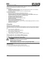
Switching relay contacts manually
The status of the relay is reflected by the slide switches (3) on the front of the device.(figure 1).
At the same time they can be used for manual operation of the relay outputs using a suitable
tool.
o Move slide switch to ON position.
Relay contact is closed, load is switched on.
o Move slide switch to OFF position.
Relay contact is open, load is switched off.
i Outputs disabled via software can still be switched manually.
5 Information for electrically skilled persons
5.1 Mounting and electrical connection
DANGER!
Electrical shock when live parts are touched.
Electrical shocks can be fatal.
Before carrying out work on the device or load, disengage all the
corresponding circuit breakers. Cover up live parts in the working environment.
Fitting the device
Observe the temperature range. Ensure adequate cooling.
o Mount device on DIN rail. Output terminals must be at the top.
2/5
82594903
j0082594903
28.06.2016
Control unit 1-10 V, 4-gang

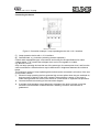
Connecting the device
Figure 2: Connection example - Lamp operating device with 1-10 V interface
(7) Lamp operation device with 1-10 V interface
(8) Switched load, e.g. luminaire (switching actuator operation)
Control cable: appropriate type, cross-section and routing for the specifications for mains
voltage cables. 1-10 V and mains voltages wires can be run together in a cable,
e.g. NYM 5x1.5 mm².
Only use lamp operating devices that are of the same type, the same power level, and from the
same manufacturer. Otherwise there may be differences in brightness between the individual
lamps.
The maximum number of lamp operating devices that can be connected is a function of the sum
of the control currents.
i Electronic lamp operating devices generate high current spikes when they are switched on,
that can result in sticking of the relay contacts. Note switch-on currents. In the case of
loads with high switch-on current, use switch-on current limiter or separate load protection.
o Connect the device according to the connection diagram .
o If multiple circuit breakers supply dangerous voltages to the device or load, couple the
miniature circuit breakers or label them with a warning, to ensure disconnection is
guaranteed.
3/5
82594903
j0082594903
28.06.2016
Control unit 1-10 V, 4-gang

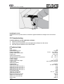
Figure 3
Installing the cover
Install the cover to protect the bus connection against hazardous voltages in the connection
area.
5.2 Commissioning
Load the address and the application software
o Switch on the bus voltage.
o Assign physical addresses and load application software into the device.
o Note the physical address on the device label.
6 Technical data
KNX
KNX medium TP
Commissioning mode S-mode
Rated voltage KNX DC 21 ... 32VSELV
Current consumption KNX max. 6mA
Power loss max. 4W
Ambient temperature -5 ... +45°C
Storage/transport temperature -25 ... +70°C
Control outputs
Control voltage 1 ... 10V
Control current per output max. 100mA
Cable length max. 500m (0.5 mm
2
)
Switching outputs
Contact type µ contact
Switching voltage AC 250 / 400V
Switching current 230 V AC 1 16A
Switching current 230 V AC 3 10A
Switching current 400 V AC 1 10A
Switching current 400 V AC 3 6A
Fluorescent lamps 16AX
Switching voltage DC DC 12 ... 24V
Switching current DC 16A
Minimum switching current 100mA
Switch-on current 150 µs 600A
Switch-on current 600 µs 300A
Ohmic load 3680W
4/5
82594903
j0082594903
28.06.2016
Control unit 1-10 V, 4-gang

Capacitive load 16 A / 200 µF
Lamp loads
Incandescent lamps 3680W
HV halogen lamps 3680W
LV halogen lamps with inductive transformer 2000VA
LV halogen lamps with Tronic transformer 2500W
Fluorescent lamps T5/T8
uncompensated 3680W
parallel compensated 2500 W / 200 µF
twin-lamp circuit 3680 W / 200 µF
Compact fluorescent lamps
uncompensated 3680W
parallel compensated 2500 W / 200 µF
Mercury vapour lamps
uncompensated 3680W
parallel compensated 3680 W / 200 µF
Connection
single stranded 0.5 ... 4mm²
Finely stranded without conductor sleeve 0.34 ... 4mm²
Finely stranded with conductor sleeve 0.14 ... 2.5mm²
Fitting width 72mm / 4modules
7 Accessories
Connection cover Art. No. 2050 K
8 Warranty
The warranty follows about the specialty store in between the legal framework as provided for
by law.
ALBRECHT JUNG GMBH & CO. KG
Volmestraße 1
58579 Schalksmühle
GERMANY
Telefon: +49 2355 806-0
Telefax: +49 2355 806-204
www.jung.de
5/5
82594903
j0082594903
28.06.2016
Control unit 1-10 V, 4-gang
-
 1
1
-
 2
2
-
 3
3
-
 4
4
-
 5
5


w innych językach
Powiązane artykuły
Inne dokumenty
-
ABB 6584-500 Instrukcja obsługi
-
Eltako ESW12DX-UC Instrukcja obsługi
-
CAME SIFCPKNX Instrukcja instalacji
-
-
Fujitsu FJ-RC-KNX-1i Intesis Instrukcja obsługi
-
Eltako ESR12NP-230V+UC Impulse Switch Instrukcja obsługi
-
Marantec Digital 351 Instrukcja obsługi
-
Yamaha PM4000 Instrukcja obsługi
-
-
Mark GSX Series Technical Manual