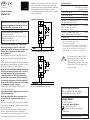
Poniżej znajdują się krótkie informacje dla Przełącznik impulsowy ESW12DX-UC. Jest to urządzenie modułowe do montażu na szynie DIN, które łączy w sobie zalety bezobsługowego sterowania elektronicznego i wysoką wydajność specjalnych przekaźników. Dzięki opatentowanej technologii Eltako Duplex (DX) styki normalnie beznapięciowe mogą przełączać się przy przejściu przez zero napięcia 230 V AC 50 Hz, co znacznie zmniejsza zużycie. Posiada uniwersalne napięcie sterujące od 8 do 230 V UC, niski poziom hałasu podczas przełączania, brak strat w trybie czuwania i unika straty mocy, dzięki zastosowaniu bistabilnego przekaźnika. Styk przekaźnika może być otwarty lub zamknięty przy uruchomieniu i zostanie zsynchronizowany przy pierwszym uruchomieniu.
Poniżej znajdują się krótkie informacje dla Przełącznik impulsowy ESW12DX-UC. Jest to urządzenie modułowe do montażu na szynie DIN, które łączy w sobie zalety bezobsługowego sterowania elektronicznego i wysoką wydajność specjalnych przekaźników. Dzięki opatentowanej technologii Eltako Duplex (DX) styki normalnie beznapięciowe mogą przełączać się przy przejściu przez zero napięcia 230 V AC 50 Hz, co znacznie zmniejsza zużycie. Posiada uniwersalne napięcie sterujące od 8 do 230 V UC, niski poziom hałasu podczas przełączania, brak strat w trybie czuwania i unika straty mocy, dzięki zastosowaniu bistabilnego przekaźnika. Styk przekaźnika może być otwarty lub zamknięty przy uruchomieniu i zostanie zsynchronizowany przy pierwszym uruchomieniu.

-
 1
1

Poniżej znajdują się krótkie informacje dla Przełącznik impulsowy ESW12DX-UC. Jest to urządzenie modułowe do montażu na szynie DIN, które łączy w sobie zalety bezobsługowego sterowania elektronicznego i wysoką wydajność specjalnych przekaźników. Dzięki opatentowanej technologii Eltako Duplex (DX) styki normalnie beznapięciowe mogą przełączać się przy przejściu przez zero napięcia 230 V AC 50 Hz, co znacznie zmniejsza zużycie. Posiada uniwersalne napięcie sterujące od 8 do 230 V UC, niski poziom hałasu podczas przełączania, brak strat w trybie czuwania i unika straty mocy, dzięki zastosowaniu bistabilnego przekaźnika. Styk przekaźnika może być otwarty lub zamknięty przy uruchomieniu i zostanie zsynchronizowany przy pierwszym uruchomieniu.
w innych językach
- English: Eltako ESW12DX-UC User manual
Powiązane artykuły
Inne dokumenty
-
Marantec Digital 351 Instrukcja obsługi
-
JUNG 2194REGHM Instrukcja obsługi
-
F F BIS-411 1R1Z Instrukcja obsługi
-
-
-
-
STEINEL XLED PRO 240 anthrazit Skrócona instrukcja obsługi
-