JUNG ULZ1215REG Instrukcja obsługi
- Kategoria
- Ściemniacze
- Typ
- Instrukcja obsługi

Universal amplifier for rail mounting 200-500 W
Light Management
Universal amplifier for rail mounting 200-500 W
Art. No. ULZ 1215 REG
Operating instructions
1 Safety instructions
Electrical equipment may only be installed and fitted by electrically skilled persons.
Serious injuries, fire or property damage possible. Please read and follow manual fully.
Danger of electric shock. Device is not suitable for disconnection from supply voltage.
The load is not electrically isolated from the mains even when the device is switched off.
Danger of electric shock. Always disconnect before carrying out work on the devise or
load. At the same time, take into account all circuit breakers that supply dangerous
voltage to the device or load.
Fire hazard. For operation with inductive transformers, each transformer must be fused
on the primary side in accordance with the manufacturer's instructions. Only safety
transformers according to EN 61558-2-6 may be used.
A minimum power of 10 kVA is required for operation on isolating transformer networks.
Otherwise it is not ensured that the dimmer will correctly recognise the dimming
principle suitable for the load. Device can be damaged.
These instructions are an integral part of the product, and must remain with the end
customer.
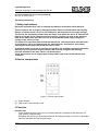
2 Device components
Figure 1: Device components
(1) Power booster
(2) LED on/off: power booster on/off
3 Function
Intended use
- Power enhancement for the Tronic or universal dimmers contained in the reference list
(see section Technical data)
- Switching and dimming of incandescent lamps, HV halogen lamps and Tronic or dimmable
inductive transformers with halogen lamps.
1/7
82557263
J:0082557263
27.02.2013

- Suitable for mixed operation up to the specified output (see section Technical data)
- Installation in distribution boxes on DIN rail according to EN 60715
i Lighting systems with an power of more than 1000 W/VA are professional applications.
i No mixed operation of Tronic and inductive transformers.
i Operation with HV LED lamps is not possible.
Product characteristics
- Connection of several power boosters to a single dimmer
- The total power of the connected loads is divided between the dimmer and power boosters.
- Power is supplied to the connected loads via a common power cable
- Operation using upstream dimmer
- Electronic over-temperature protection
i Flickering of the connected lamps due to undershoot of the specified minimum load or
through centralised pulses from the power stations. This does not represent any defect in
the device.
i Brightness differences between the lighting on a dimmer without powerpower booster and
a dimmer with power booster are possible.
4 Information for electrically skilled persons
4.1 Fitting and electrical connection
DANGER!
Electrical shock when live parts are touched.
Electrical shocks can be fatal.
Before carrying out work on the device or load, disengage all the
corresponding circuit breakers. Cover up live parts in the working environment.
Fitting and connecting the power booster
i To prevent overheating, maintain a distance of 1 module when operating multiple dimmers
or power units within the same control cabinet.
i The terminals must be at the top.
o Snap power booster onto DIN rail.
CAUTION!
Destruction of the devices when connected to the wrong outer conductor.
The dimmer and power boosters will be destroyed.
Connect all devices to the same outer conductor.
2/7
82557263
J:0082557263
27.02.2013
Light Management
Universal amplifier for rail mounting 200-500 W

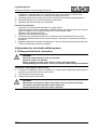
Figure 2: Connection diagram with RMD dimmer
Figure 3: Connection diagram with FM dimmer
3/7
82557263
J:0082557263
27.02.2013
Light Management
Universal amplifier for rail mounting 200-500 W

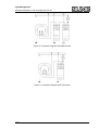
Figure 4: Connection diagram with multiple power boosters
(1) Power booster
(3) Dimmer
(4) Local extension
i Pay attention to the necessary cable cross-section of the common power cable.
i If multiple power boosters are used, add up the minimum loads of all the separate devices.
i In the case of lighting systems with an output of over 3500 W/VA, the installation must be
distributed across two miniature circuit breakers with the same conductor.
o Connect the power booster according to the connection diagram, connection diagram with
RMD dimmer (figure 2), connection diagram with FM dimmer (figure 3) or connection
diagram with multiple power boosters (figure 4).
o If multiple circuit breakers supply dangerous voltages to the device or load, couple the
circuit breakers to ensure tripping.
Calculation example for the number of power boosters required:
P
L
Load to be dimmed, e.g. 2200 W
P
D
Max. dimmer load, e.g. 500 W
P
LZ
Max. universal power extension load, e.g. B.
500 W
P
LZG
Power that the power boosters have to provide
n Number of power boosters required
Calculation of the load to be covered by power boosters:
P
L
- P
D
= P
LZG
P
LZG
= 2200 W - 500 W = 1700 W
Number of power power boosters:
P
LZG
/
PLZ
= n
n = 1700 / 500 = 3.4
4 power boosters are required for the loads assumed in the example.
5 Appendix
5.1 Technical data
Rated voltage AC 230 V ~
Mains frequency 50 / 60 Hz
Ambient temperature +5 ... +45 °C
4/7
82557263
J:0082557263
27.02.2013
Light Management
Universal amplifier for rail mounting 200-500 W

Power loss 5 W
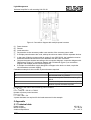
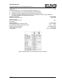
Connected load at 25 °C see reference list (figure 5)(figure 6)
i Power specifications including transformer power dissipation.
i Operate inductive transformers with at least 85% nominal load.
i For ohmic-inductive mixed load, maximum 50% proportion of ohmic load. Otherwise
incorrect calibration of the dimmer may result.
capacitive-inductive not permitted
Minimum connected load 200 W/VA
Power reduction
per 5°C in excess of 45°C -15 %
Connection
single stranded max. 4 mm²
finely stranded with conductor sleeve 0.5 ... 2.5 mm²
finely stranded without conductor sleeve 0.75 ... 4 mm²
Number of power boosters see reference list
Total length power cable max. 100 m
Fitting width 36 mm / 2 modules
Figure 5: Reference list of conventional and radio dimmers
5/7
82557263
J:0082557263
27.02.2013
Light Management
Universal amplifier for rail mounting 200-500 W

Figure 6: Reference list KNX dimmer
The icons used to label the dimmer load shows the load type that can be connected
to a dimmer and the electric behaviour of a load:
R = ohmic, L = inductive, C = capacitive
5.2 Troubleshooting
System has switched off.
Cause 1: short-circuit protection has tripped. The power booster behaves like the upstream
dimmer.
Eliminate short-circuit.
i The short-circuit protection is not based on a conventional fuse. Thus the load circuit is not
interrupted electrically.
Cause 2: overheating protection has tripped.
Disconnect system from mains, switch off circuit breakers.
Let system cool down for approx. 15 minutes.
Check the installation situation.
Reduce the connected load.
Switch circuit breakers and system on again.
i Load is initially distributed to the remaining devices. The further behaviour of the system
depends on the dimmer used and the number, utilisation and installation situation of the
devices.
5.3 Warranty
We reserve the right to make technical and formal changes to the product in the interest of
technical progress.
We provide a warranty as provided for by law.
Please send the unit postage-free with a description of the defect to our central customer
service office.
6/7
82557263
J:0082557263
27.02.2013
Light Management
Universal amplifier for rail mounting 200-500 W

ALBRECHT JUNG GMBH & CO. KG
Volmestraße 1
58579 Schalksmühle
Telefon: +49.23 55.8 06-0
Telefax: +49.23 55.8 06-2 04
www.jung.de
Service Center
Kupferstr. 17-19
44532 Lünen
Germany
7/7
82557263
J:0082557263
27.02.2013
Light Management
Universal amplifier for rail mounting 200-500 W
-
 1
1
-
 2
2
-
 3
3
-
 4
4
-
 5
5
-
 6
6
-
 7
7


JUNG ULZ1215REG Instrukcja obsługi
- Kategoria
- Ściemniacze
- Typ
- Instrukcja obsługi
w innych językach
Powiązane artykuły
Inne dokumenty
-
Eltako EUD12DK/800W-UC Universal dimmer switch Instrukcja obsługi
-
-
Eltako DTD65L-230V-wg Instrukcja obsługi
-
Yamaha P2050 Instrukcja obsługi
-
-
-
OJ Electronics MDC-13 Instrukcja obsługi
-
CAME 846NC-0120 Instrukcja instalacji
-
ABB 6584-500 Instrukcja obsługi