
DE Original-
Betriebsanleitung
EN Instruction Manual
FR
Instructions de service
NL Gebruikshandleiding
IT Istruzioni per l‘uso
PL Instrukcja eksploatacji
CZ Návod pro provoz
SK Návod na prevádzku
HU Üzemeltetési útmutató
RO Manual de utilizare
ZH 手册
JUNG-PUMPEN.DE B 42951-31-1902
COMPLI
108/2 ME 108/2 M 120/2 M
300 E
400 E 400
508/2 ME 508/2 M 520/2 M
510/4 BW 515/4 BW 525/4 BW 525/2 BW 535/2 BW
1008/2 ME 1008/2 M 1020/2 M 1010/4 BWE
1010/4 BW 1015/4 BW 1025/4 BW 1025/2 BW 1035/2 BW
1210/4 BW 1215/4 BW 1225/4 BW 1225/2 BW 1235/2 BW

Sie haben ein Produkt von Pentair Jung Pumpen gekauft
und damit Qualität und Leistung erworben. Sichern Sie sich
diese Leistung durch vorschriftsmäßige Installation, damit
unser Produkt seine Aufgabe zu Ihrer vollen Zufriedenheit
erfüllen kann. Denken Sie daran, dass Schäden infolge un-
sachgemäßer Behandlung die Gewährleistung beeinträchti-
gen. Beachten Sie deshalb die Hinweise der Betriebsanlei-
tung!
Dieses Gerät kann von Kindern ab 8 Jahren und darüber
sowie von Personen mit verringerten physischen, sensori-
schen oder mentalen Fähigkeiten oder Mangel an Erfahrung
und Wissen benutzt werden, wenn sie beaufsichtigt oder
bezüglich des sicheren Gebrauchs des Gerätes unterwiesen
wurden und die daraus resultierenden Gefahren verstehen.
Kinder dürfen nicht mit dem Gerät spielen. Reinigung und
Benutzer-Wartung dürfen nicht von Kindern ohne Beauf-
sichtigung durchgeführt werden.
Schadensvermeidung bei Ausfall
Wie jedes andere Elektrogerät kann auch dieses Produkt
durch fehlende Netzspannung oder einen technischen Defekt
ausfallen.
Wenn Ihnen durch den Ausfall des Produktes ein Schaden
(auch Folgeschaden) entstehen kann, sind von Ihnen insbeson-
dere folgende Vorkehrungen nach Ihrem Ermessen zu treffen:
•Einbau einer wasserstandsabhängigen (unter Umständen
auch netzunabhängigen) Alarmanlage, so dass der Alarm vor
Eintritt eines Schadens wahrgenommen werden kann.
•Prüfung des verwendeten Sammelbehälters / Schachtes auf
Dichtig keit bis Oberkante vor Inbetriebnahme des Produktes.
•Einbau von Rückstausicherungen für diejenigen Entwässe-
rungsgegenstände, bei denen durch Abwasseraustritt nach
Ausfall des Produktes ein Schaden entstehen kann.
•Einbau eines weiteren Produktes, das den Ausfall des Pro-
duktes kompensieren kann (z.B. Doppelanlage).
•Einbau eines Notstromaggregates.
Da diese Vorkehrungen dazu dienen, Folgeschäden beim Aus-
fall des Produktes zu vermeiden bzw. zu minimieren, sind sie
als Herstellerrichtlinie – analog zu den normativen Vorgaben
der DIN EN als Stand der Technik – zwingend bei der Verwen-
dung des Produktes zu beachten (OLG Frankfurt/Main, Az.: 2 U
205/11, 15.06.2012).
SICHERHEITS HINWEISE
Diese Betriebsanleitung enthält grundlegende Informationen,
die bei Installation, Betrieb und Wartung zu beachten sind. Es
ist wichtig, dass diese Betriebsanleitung unbedingt vor Mon-
tage und Inbetriebnahme vom Monteur sowie dem zuständi-
gen Fachpersonal/Betreiber gelesen wird. Die Anleitung muss
ständig am Einsatzort der Pumpe beziehungsweise der Anlage
verfügbar sein.
Die Nichtbeachtung der Sicherheitshinweise kann zum Verlust
jeglicher Schadenersatzansprüche führen.
In dieser Betriebsanleitung sind Sicherheitshinweise mit Sym-
bolen besonders gekennzeichnet. Nichtbeachtung kann ge-
fährlich werden.
Allgemeine Gefahr für Personen
Warnung vor elektrischer Spannung
HINWEIS! Gefahr für Maschine und Funktion
Personalqualikation
Das Personal für Bedienung, Wartung, Inspektion und Monta-
ge muss die entsprechende Qualikation für diese Arbeiten
aufweisen und sich durch eingehendes Studium der Betriebs-
anleitung ausreichend informiert haben. Verantwortungsbe-
reich, Zuständigkeit und die Überwachung des Personals müs-
sen durch den Betreiber genau geregelt sein. Liegen bei dem
Personal nicht die notwendigen Kenntnisse vor, so ist dieses
zu schulen und zu unterweisen.
Sicherheitsbewusstes Arbeiten
Die in dieser Betriebsanleitung aufgeführten Sicherheitshin-
weise, die bestehenden nationalen Vorschriften zur Unfall-
verhütung sowie eventuelle interne Arbeits-, Betriebs- und
Sicherheitsvorschriften sind zu beachten.
Sicherheitshinweise für den Betreiber/
Bediener
Gesetzliche Bestimmungen, lokale Vorschriften und Sicher-
heitsbestimmungen müssen eingehalten werden.
Gefährdungen durch elektrische Energie sind auszuschließen.
Leckagen gefährlicher Fördergüter (z.B. explosiv, giftig, heiß)
müssen so abgeführt werden, dass keine Gefährdung für Per-
sonen und die Umwelt entsteht. Gesetzliche Bestimmungen
sind einzuhalten.
Sicherheitshinweise für Montage-,
Inspektions- und Wartungsarbeiten
Grundsätzlich sind Arbeiten an der Maschine nur im Stillstand
durchzuführen. Pumpen oder -aggregate, die gesundheitsge-
fährdende Medien fördern, müssen dekontaminiert werden.
Unmittelbar nach Abschluss der Arbeiten müssen alle Sicher-
heits- und Schutzeinrichtungen wieder angebracht bzw. in
Funktion gesetzt werden. Ihre Wirksamkeit ist vor Wiederinbe-
triebnahme unter Beachtung der aktuellen Bestimmungen und
Vorschriften zu prüfen.
Eigenmächtiger Umbau und
Ersatzteilherstellung
Umbau oder Veränderung der Maschine sind nur nach Abspra-
che mit dem Hersteller zulässig. Originalersatzteile und vom
Hersteller autorisiertes Zubehör dienen der Sicherheit. Die
Verwendung anderer Teile kann die Haftung für die daraus ent-
stehenden Folgen aufheben.
Unzulässige Betriebsweisen
Die Betriebssicherheit der gelieferten Maschine ist nur bei
bestimmungsgemäßer Verwendung gewährleistet. Die ange-
gebenen Grenzwerte im Kapitel "Technische Daten" dürfen auf
keinen Fall überschritten werden.
Hinweise zur Vermeidung von Unfällen
Vor Montage- oder Wartungsarbeiten sperren Sie den Arbeits-
bereich ab und prüfen das Hebezeug auf einwandfreien Zu-
stand. Arbeiten Sie nie allein und benutzen Sie Schutzhelm,
Schutzbrille und Sicherheitsschuhe, sowie bei Bedarf einen
geeigneten Sicherungsgurt.
Bevor Sie schweissen oder elektrische Geräte benutzen, kont-
rollieren Sie, ob keine Explosionsgefahr besteht.
Wenn Personen in Abwasseranlagen arbeiten, müssen sie gegen
evtl. dort vorhandene Krankheitserreger geimpft sein. Achten Sie
2
DEUTSCH

auch sonst peinlich auf Sauberkeit, Ihrer Gesundheit zu Liebe.
Stellen Sie sicher, dass keine giftigen Gase im Arbeitsbereich
vorhanden sind.
Beachten Sie die Vorschriften des Arbeitsschutzes und halten
Sie Erste-Hilfe-Material bereit.
In einigen Fällen können Pumpe und Medium heiß sein, es be-
steht dann Verbrennungsgefahr.
Für Montage in explosionsgefährdeten Bereichen gelten be-
sondere Vorschriften!
EINSATZ
Die steckerfertigen Fäkalienhebeanlagen compli sind LGA
Bauart geprüft und eignen sich zum Heben von Abwässern aus
Toiletten- und Urinalanlagen sowie von häuslichem Schmutz-
wasser mit den üblichen Beimengungen.
Die Behälter sind überutbar mit einer max. Höhe von 2 mWS
und einer Dauer von längstens 7 Tagen.
Die Steuerung ist nicht überutbar, aber spritzwasserge-
schützt nach IP 44.
Bei vorschriftsmäßiger Installation und bestimmungsgemä-
ßen Einsatz erfüllt die Steuerung die Schutzanforderungen
der EMC-Richtlinie 2014/30/EU und ist für den Einsatz im
häuslichen Bereich am öffentlichen Stromversorgungsnetz
geeignet. Bei Anschluss an ein Industrienetz innerhalb eines
Industriebetriebes mit einer Stromversorgung aus eigenem
Hochspannungstransformator ist u.U. mit unzureichender
Störfestigkeit zu rechnen.
Beim Einsatz der Anlagen müssen die jeweiligen nationalen
Gesetze, Vorschriften sowie die örtlichen Bestimmungen ein-
gehalten werden, wie z.B.
•Abwasserhebeanlagen für die Gebäude- und Grundstücks-
entwässerung (z.B. in Europa EN 12050 und 12056)
•Errichten von Niederspannungsanlagen (z.B. in Deutschland
VDE 0100)
•Sicherheit und Arbeitsmittel (z.B. in Deutschland BetrSichV
und BGR 500)
•Sicherheit in abwassertechnischen Anlagen (z.B. in Deutsch-
land GUV-VC5, GUV-R104, GUV-R126)
•Elektrische Anlagen und Betriebsmittel (z.B. in Deutschland
GUV-VA3)
•Explosionsschutz EN 60079-0, EN 60079-1, EN 60079-14, EN
60079-17 und EN 1127-1
Lieferumfang
•Behälter mit Pumpe(n) und Klemmansch für den Zulauf
•Reduzierstück DN 150 / DN 100 für compli 500 und 1000
•Überschiebmuffe für die Lüftung (compli 1200 elastische
Verbindungen mit Schellen)
•Anschlussansch für die Druckleitung
•elastische Verbindung mit Schellen für die Druckleitung
•Steckdichtung(en) für die Handmembranpumpe oder weite-
ren Zulauf DN 50
•Befestigungsmaterial für den Behälter
•Rückschlagklappe für die Druckleitung (compli 300, 500,
1000 und 1200)
•Steuerung (nicht compli 300)
Betriebsart: Aussetzbetrieb S3, siehe techn. Daten
EINBAU
Die Hebeanlage muss auftriebssicher und freistehend ein-
gebaut werden. Neben und über allen zu bedienenden und zu
wartenden Teilen muss ein Arbeitsraum von mindestens 60 cm
Breite bzw. Höhe vorhanden sein.
Lüftung: Die Lüftungsleitung muss über Dach geführt werden.
Zulauf: Im Zulauf vor dem Behälter muss ein Schmutzwasser-
schieber angeordnet werden.
Druckleitung: Hinter der Rückschlagklappe in der Drucklei-
tung muss ein weiterer Schmutzwasserschieber angeordnet
werden. Ist die Rückschlagklappe nicht im Lieferumfang der
Anlage enthalten, muss hier ein EN-geprüfter Rückussver-
hinderer eingebaut werden.
Die Druckleitung muss mit einer Schleife über die örtliche
Rückstauebene geführt werden.
Für die Entwässerung des Aufstellungsraumes ist ein Pum-
pensumpf vorzusehen.
HINWEIS! Alle Schrauben, die zur Befestigung von Einzelteilen
am Behälter dienen, dürfen nur mit einem max. Drehmoment
von 6 Nm angezogen werden.
Montage Behälter
Den Schieber im Zulauf (Zubehör) schließen, um Wassereintritt
während der Montage zu verhindern.
compli 300. Den gewünschten Zulauf DN 100, seitlich oder
oben mit einer Lochsäge Ø 102 oder einer Stichsäge an der
Markierung öffnen und entgraten. Den beiliegenden Klemm-
ansch mit den Sechskantschrauben am Zulauf locker befes-
tigen.
Die Winkel zum Verankern der Anlage an den Behälter schrau-
ben und dann die Anlage mit dem Klemmansch bis zum An-
schlag auf das Zulaufrohr schieben.
Dann die Markierungen für die Bodendübel anzeichnen und
bohren und den Dübel einsetzen.
Jetzt kann der Klemmansch festgezogen werden und die An-
lage mit den Holzschrauben und Scheiben am Boden verankert
werden.
Alle anderen compli. Hebeanlage mit dem Klemmansch bis
zum Anschlag auf das Zulaufrohr schieben und ausrichten.
Soll ein seitlicher Zulauf DN 150 genutzt werden, so muss er
zuerst mit einer Lochsäge Ø 152 an der Markierung geöffnet
und entgratet werden. Der Standardzulauf muss dann mit dem
Verschlussset (Zubehör) verschlossen und das Einschaltniveau
neu festgelegt werden.
Bei den compli 500 und 1000 kann der Zulauf von DN 150 auf DN
100 verringert werden, wenn das beiliegende Reduzierstück
zuerst in den Klemmansch eingesetzt wird.
Die Sechskantschrauben des Klemmansches fest anziehen.
Löcher für die Bodenbefestigung des Behälters anzeichnen
und bohren.
Holzschraube mit Scheibe und Dübel zusammen durch die Be-
hälterbohrung stecken und festschrauben.
HINWEIS! Die Schrauben nur so fest ziehen, dass sich der Be-
hälter nicht verformt, sonst besteht die Gefahr einer Undich-
tigkeit.
Bei den Anlagen der Baureihe compli 1200 wird der Behälter
zusätzlich noch mit zwei seitlichen Winkeln befestigt.
Montage Lüftung
Die Lüftungsleitung mit der Überschiebmuffe DN 70 rechts
oben am Behälter anschließen und über Dach führen.
Bei der compli 1200 den oberen rechten Stutzen Ø 78 mm an
der Markierung abschneiden und entgraten. Jetzt die Lüf-
3
DEUTSCH

tungsleitung mit der elastischen Verbindung DN 70 anschlie-
ßen und über Dach führen.
Montage Druckleitung
Auf den Abgangsansch montieren:
1. Rückschlagklappe (wenn nicht Lieferumfang)
2. Absperrschieber (Zubehör)
3. Anschlussansch und
4. mit elastischer Verbindung die Druckleitung anschließen und
mit einer Schleife über die örtliche Rückstauebene führen.
Anschluss DN 50 vertikel zur Notentsorgung
Dieser Anschluss wird zum Anschluss einer Handmembran-
pumpe genutzt.
Den Stutzen an der Markierung mit einer Lochsäge öffnen und
entgraten.
Die Steckdichtung 58/50 einsetzen.
Zulaufrohr mit Außen-Ø 50 mm durch die Steckdichtung in den
Behälter schieben. Der Abstand zum Behälterboden sollte 50
mm betragen.
Die Handmembranpumpe gut zugänglich an der Wand befes-
tigen, mit dem eingeschobenen Rohr verbinden und dann die
Druckleitung der Handmembranpumpe anschließen. Auch
hier muss die Druckleitung mit einer Schleife über die örtliche
Rückstauebene geführt werden.
Zusatzzulauf DN 50 horizontal
Die vorgefertigte Nut für den zusätzlichen Zulauf mit einer
Lochkreissäge öffnen und die entgraten.
Die Steckdichtung 58/50 einsetzen.
Zulaufrohr mit Außen-Ø 50 mm durch die Steckdichtung in den
Behälter schieben.
HINWEIS! Die Anschlussleitungen an den niedrigen seitlichen
Zuläufen der compli 300 sind möglichst nahe an der Anlage mit
einem sogenannten Anstaubogen zu versehen. Dieser Bogen
muss mindestens eine Höhe von 180 mm zwischen Rohrsohle
und Aufstellebene haben. Durch Luftpolster in der Anschluss-
leitung kann es zu Ablaufproblemen und Rückstau kommen.
Um diesen Rückstau zu vermeiden, ist die Zulaueitung in ih-
rem Hochpunkt zu entlüften. Die Lüftungsleitung kann an die
Behälterlüftung angeschlossen werden.
ELEKTROANSCHLUSS
HINWEIS! Nur eine Elektrofachkraft darf an Pumpe, Stecker
oder Steuerung Elektroarbeiten vornehmen.
WARNUNG!
Vor jeder Arbeit den Netzstecker der Anlage ziehen und sicher-
stellen, dass die Anlage von anderen Personen nicht wieder un-
ter Spannung gesetzt werden kann.
HINWEIS! Netzstecker niemals ins Wasser legen! Eventuell
eindringendes Wasser kann zu Störungen und Schäden führen.
Die jeweils gültigen Normen (z.B. EN), landesspezischen Vor-
schriften (z.B. VDE) sowie die Vorschriften der örtlichen Ver-
sorgungsnetzbetreiber sind zu beachten.
Betriebsspannung beachten (siehe Typenschild)!
Die Anlagen besitzen eine Niveauschaltung, die die Pumpe,
abhängig vom Wasserstand, ein- bzw. abschaltet. Der Piepton
der eingebauten Alarmanlage signalisiert, dass eine Funkti-
onsstörung vorliegt, auch wenn dies nur vorübergehend ist.
Ist die Pumpe zu warm geworden, wird sie durch den Wick-
lungsthermostaten abgeschaltet. Vor dem Beseitigen der Stö-
rungsursache muss der Netzstecker gezogen werden, da die
Pumpe sonst nach dem Abkühlen selbsttätig wieder einschal-
tet. Eine direkte Störmeldung erfolgt nicht.
Anlagen in Wechselstrom
Die Anlage darf nur an eine vorschriftsmäßig installierte
Steckdose angeschlossen werden, die sich in einem trocke-
nen Raum oberhalb der Rückstauebene bendet und mit 16 A
(träge) abgesichert ist.
Anlagen in Drehstrom
Für den Elektroanschluss der Hebeanlage ist eine vorschrifts-
mäßig installierte 5-polige CEE-Steckdose vorzusehen, die
sich in einem trockenen Raum oberhalb der Rückstauebene
bendet (3/N/PE~230/400 V).
HINWEIS! Als Vorsicherungen für die Anlage sind nur träge Si-
cherungen oder Automaten mit C-Charakteristik einzusetzen.
Montage der Steuerung (nicht compli 300)
Die Steuerung nur in trockenen Räumen oberhalb der Rück-
stauebene betreiben und das Gehäuse stets geschlossen
halten. Die Steuerung muss gut zugänglich sein, damit eine
Kontrolle jederzeit möglich ist. Hohe Luftfeuchtigkeit und
Schwitzwasser kann die Steuerung zerstören.
Schaltniveaus
Die Ein- und Ausschaltpunkte sind ab Werk für die Standardzu-
laufhöhe der jeweiligen Anlage eingestellt.
Sollten Sie eine andere Zulaufhöhe wählen, so müssen Sie den
Einschaltpunkt neu denieren (nicht compli 300), da es sonst
evtl. zu einem Rückstau im Zulauf kommen kann.
Die anderen Schaltpunkte für Alarm (+ 2 cm) und bei Doppel-
anlagen Spitzenlast (+4 cm) werden von der Steuerung dann
automatisch entsprechend neu gesetzt.
Einschaltniveau neu festlegen (nicht compli 300)
Die Anlage vorübergehend stillsetzen, Hand-0-Automatik-
Schalter auf "0" setzen. Das Justieren des Einschaltpunktes
erfolgt im Modul "Analogauswerter K1" rechts seitlich in der
Steuerung. Entfernen Sie vorübergehend die Klarsichtabde-
ckung des Moduls.
Auf dem Analogauswerter benden sich drei Leuchtdioden,
die mit P1 - P2 - P3 bezeichnet sind.
– P1 = Diagnosefunktion,
–P2 leuchtet = Wasserstand liegt über Ausschaltniveau aber
noch unter Einschaltniveau
– P3 leuchtet = Wasserstand hat Einschaltniveau erreicht
Füllen Sie den Sammelbehälter bis zur Unterkante des Zulaufs
mit Wasser. Es darf nur P2 leuchten, wenn auch P3 leuchtet,
muss nachgeregelt werden:
Drehen Sie die kleine Stellschraube unterhalb von P1 ein bis
zwei Umdrehungen im Uhrzeigersinn. Jetzt den Schwimmer
im Behälter unter den Ausschaltpunkt tauchen und wieder auf-
schwimmen lassen. Leuchtet P3 immer noch, drehen Sie die
Stellschraube eine weitere Umdrehung im Uhrzeigersinn und
4
DEUTSCH

tauchen den Schwimmer erneut unter.
Diesen Vorgang solange wiederholen bis P3 nicht mehr leuch-
tet, dann drehen Sie die Stellschraube vorsichtig im Gegen-
uhrzeigersinn zurück, bis P3 gerade wieder leuchtet. Der Ein-
schaltpunkt ist gesetzt.
Alarmanlage
Störungsmeldungen erfolgen sowohl optisch als auch akus-
tisch. Die serienmäßig netzabhängige Alarmanlage meldet
Motorstörungen der Pumpe (rote LED, nicht bei AD 00 und
compli 300). Gleichzeitig ertönt ein integrierter akustischer
Alarm. Dies akustische Signal lässt sich nur durch Störungsbe-
seitigung oder generell abstellen.
Lässt der Montageort keine akustische Kontrolle der Stör-
meldung zu, so kann das Alarmsignal über den potentialfrei-
en Kontakt (Klemmen 40 und 41) auf der Platine (compli 300
im Stecker) weitergeführt werden. Der Schließerkontakt der
Sammelstörung ist max. mit 5A / 250V AC belastbar. Der Kon-
takt öffnet nach Störungsbeseitigung.
Akku für Alarmanlage (nicht compli 300)
Die Alarmeinrichtung ist serienmäßig netzabhängig – d.h. im
Falle eines Stromausfalls kann kein Hochwasseralarm aus-
gelöst werden. Um die Alarmanlage auch bei Stromausfall
funktionsfähig zu halten, muss ein Akku eingesetzt werden.
Klarsichttür öffnen. Akku am Anschlussclip anschließen und
am vorgesehenen Platz auf der Platine mit dem vorhandenen
Kabelbinder befestigen. Dieser kann die Alarmanlage bei Dau-
eralarm für ca. 1 Stunde mit Strom versorgen.
Nach Netzspannungswiederkehr wird der Akku automatisch
wieder aufgeladen. Ein entladener Akku ist innerhalb von ca.
24 Stunden betriebsbereit, Vollladung ist nach ca. 100 Stunden
erreicht.
Funktionsfähigkeit des Akkus regelmäßig prüfen! Dazu die
Netzspannung abschalten und eine Hochwassermeldung aus-
lösen. Die Lautstärke des akustischen Alarms darf sich über
mehrere Minuten nicht wesentlich verringern. Die Lebensdau-
er liegt bei ca. 5 Jahren. Einsetzdatum auf dem Akku notieren
und nach 5 Jahren vorsorglich auswechseln.
VORSICHT!
Nur 9V-NiMh-Akku des Herstellers verwenden! Bei Verwendung
von Trockenbatterien oder Lithium Akkus besteht Explosions-
gefahr!
Betriebsstundenzähler
Optional kann ein Betriebsstundenzähler in die Steuerung ein-
gesetzt werden (nicht compli 300). Hierzu die Anschlüsse des
Betriebsstundenzählers auf ca. 8 mm kürzen und auf der Plati-
ne am Platz BSZ in die 4 Buchsen stecken. Falls nach dem er-
neuten Einschalten der Anlage keine Anzeige erfolgt, muss der
Betriebsstundenzähler um 180° gedreht werden.
Internen Alarmsummer stilllegen
Nicht compli 300. Den versiegelten Jumper (BRX/BRX1) abzie-
hen. Damit der Stecker nicht verloren geht, Jumper auf einen
Stift der 2-poligen Stiftleiste wieder aufstecken.
Externer Alarmsummer (Zubehör)
Klarsichttür der Steuerung öffnen.
An den Klemmen "S+" und "S-" kann ein zusätzlicher, separater
akustischer 12 VDC-Signalgeber mit einer Stromaufnahme von
max. 30 mA angeschlossen werden. Der interne Alarmsummer
kann wahlweise ein- oder ausgeschaltet sein.
Bei der compli 300 kann ein netzunabhäniger Alarm als Zube-
hör montiert werden, ein Montagesockel ist am Behälter vor-
handen.
Bei Doppelanlagen: Externe Blitz- oder
Warnleuchte (Zubehör)
230V~Leuchte (max.1A) an Klemme N und 41 anschließen.
Isolierte Drahtbrücke von Klemme U~ nach 40 legen. Der
Stromkreis ist durch F1 abgesichert.
Die Steckbrücke "BRX2" wie folgt einstellen:
Blitzleuchte: abgezogen ( = )
Warnleuchte: aufgesteckt ( _Π_Π_ ).
BETRIEB
Probelauf und Funktionsprüfung
1. Reinigungsdeckel am Behälter öffnen.
2. Schieber in Zulauf- und Druckleitung öffnen.
3. Anlage an Spannung legen, Drehfeldrichtungsanzeige be-
achten.
4. Behälter bis zum Einschaltniveau füllen.
5. Pumpe schaltet jetzt ein und entleert den Behälter. Pump-
vorgang durch die Reinigungsöffnung beobachten.
6. Schwimmer der Niveau-Schaltung von Hand langsam über
den Einschaltpunkt hinaus anheben, bis die Alarmanlage
auslöst.
7. Reinigungsöffnung wieder mit Deckel und Dichtung ver-
schließen.
8. Anhand von mehreren Schaltspielen die Dichtigkeit des Be-
hälters, der Armaturen und der Rohrleitungen prüfen.
Automatikbetrieb
Der Automatikbetrieb ist der normale Anlagenbetrieb. Hierzu
muss der Wippschalter in die Stellung "Automatik" gebracht
werden. Durch die integrierte Niveauschaltung wird die Pumpe
entsprechend dem Flüssigkeitsstand im Behälter ein- und aus-
geschaltet. Der Betrieb der Pumpe (bei compli 300 Betriebsbe-
reitsschaft) wird durch eine grüne Leuchtdiode angezeigt.
HINWEIS! Bei ausnahmsweise großen Zuussmengen (z.B.
Poolentwässerung) ist der Schieber im Zulauf soweit zu dros-
seln, dass die Hebeanlage auch weiterhin im normalen Schalt-
betrieb arbeitet (kein Dauerlauf, sonst besteht Überhitzungs-
gefahr des Pumpenmotors).
Handbetrieb
Den Wippschalter in die Stellung "Hand" bringen. Die Pumpe ar-
beitet nun unabhängig vom Abwasserniveau im Dauerbetrieb.
Das Abpumpen sollte deshalb durch die Reinigungsöffnung be-
obachtet werden.
Stillsetzen
Wippschalter in die Stellung "0" bringen, die Pumpe ist nun still-
gesetzt. Die Alarmanlage ist weiter betriebsbereit.
GEFAHR!
Für Reparatur- und Wartungsarbeiten an Steuerung oder Pum-
pe nicht die Stellung "0" benutzen, sondern immer Netzstecker
aus der Steckdose ziehen.
5
DEUTSCH

Inspektion
Zur Erhaltung der Betriebssicherheit ist monatlich eine Sicht-
kontrolle der Anlage einschließlich der Rohrverbindungen vor-
zusehen.
WARTUNG
Wartung und Inspektion dieses Produktes sind nach EN 12056-
4 vorzunehmen. Um eine dauerhafte Betriebssicherheit Ihrer
Anlage zu gewährleisten, empfehlen wir einen Wartungsver-
trag abzuschließen.
HINWEIS! Die Wartung der Fäkalienhebeanlage und Maßnah-
men zur Instandhaltung sind von Fachkundigen in Abständen
von 3 Monaten in Gewerbebetrieben, 6 Monaten in Mehrfami-
lienhäusern oder 12 Monaten in Einfamilienhäusern durchzu-
führen.
WARNUNG!
Vor jeder Arbeit den Netzstecker der Anlage ziehen und sicher-
stellen, dass die Anlage von anderen Personen nicht wieder un-
ter Spannung gesetzt werden kann.
WARNUNG!
Anschlusskabel auf mechanische und chemische Beschädi-
gung prüfen. Beschädigte oder geknickte Kabel müssen er-
setzt werden.
Wir empfehlen bei der Wartung folgende Arbeiten vorzuneh-
men:
1. Prüfen der Verbindungsstellen auf Dichtigkeit durch Absu-
chen des Umfeldes von Anlagen und Armaturen.
2. Betätigen der Schieber; Prüfen auf leichten Gang, gegebe-
nenfalls nachstellen und einfetten.
3. Öffnen und Reinigen des Rückussverhinderers; Kontrolle
von Sitz und Kugel (Klappe).
4. Reinigen der Pumpe und des unmittelbar angeschlossenen
Leitungsbereichs; Prüfen des Laufrades und der Lagerung.
VORSICHT!
Abgenutzte Laufräder können scharfe Kanten haben.
5. Ölkontrolle, erforderlichenfalls nachfüllen oder Ölwechsel
(wenn Ölkammer vorhanden).
6. Innenreinigung des Behälters (bei Bedarf bzw. nach speziel-
len Erfordernissen) z.B. Fett entfernen.
7. Prüfen des Zustandes des Sammelbehälters.
8. Alle 2 Jahre Durchspülen der Anlage mit Wasser.
9. Prüfen des elektrischen Teils der Anlage. Die Steuerung
selbst ist wartungsfrei, sollte allerdings ein Akku eingebaut
sein, so ist er regelmäßig auf Funktionsfähigkeit zu kontrol-
lieren. Dazu bei spannungsloser Anlage den Schwimmer im
Behälter anheben, bis ein Hochwasseralarm ertönt. Außer-
dem ist der Schwimmer falls erforderlich zu reinigen.
Nach Erledigung der Wartungsarbeiten ist die Anlage nach
Durchführung eines Probelaufes wieder in Betrieb zu nehmen.
Über die Wartung ist ein Protokoll anzufertigen mit Angabe al-
ler durchgeführten Arbeiten und der wesentlichen Daten.
Ölkontrolle
(Gilt nur für 08/2, 25/2 und 35/2 Anlagen) Als erstes werden die
Sechskant- bzw. Inbusschrauben um die Pumpe herum gelöst
und die Pumpe wird mit Laufrad vom Behälter genommen. Die
Füll- und Entleerungsöffnung der Ölkammer ist durch die Ver-
schlussschraube "Öl" nach außen abgedichtet. Zur Kontrolle
der Gleitringdichtung wird das Öl der Ölkammer einschließlich
der Restmenge abgelassen und in einem sauberen Messbe-
cher aufgefangen.
•Ist das Öl mit Wasser durchsetzt (milchig), muss ein Ölwech-
sel gemacht werden. Nach weiteren 300 Betriebsstunden,
max. jedoch nach 6 Monaten, erneut kontrollieren!
•Ist das Öl jedoch mit Wasser und Schmutzstoffen durch-
setzt, muss neben dem Öl auch die Gleitringdichtung ersetzt
werden. Zur Überwachung der Ölkammer kann, auch nach-
träglich, die Elektrode unseres Dichtungskontrollgerätes
"DKG" anstelle der Verschlussschraube "DKG" montiert wer-
den.
Ölwechsel
(Gilt nur für Anlagen mit den Pumpentypen 08/2, 25/2 und 35/2)
Zur Erhaltung der Funktionssicherheit ist ein erster Ölwechsel
nach 300 und weitere Ölwechsel nach jeweils 1000 Betriebs-
stunden durchzuführen. Bei geringeren Betriebsstunden ist
aber mindestens einmal jährlich ein Ölwechsel durchzuführen.
Wird Abwasser mit stark abrasiven Beimengungen gefördert,
sind die Ölwechsel in entsprechend kürzeren Intervallen vor-
zusehen.
Für den Wechsel der Ölkammerfüllung ist Hydraulik-Mineralöl
HLP der Viskositätsklasse 22 bis 46 zu verwenden, z.B. Nuto
von ESSO oder DTE 22, DTE 24, DTE 25 von Mobil.
Die Füllmenge beträgt 380 cm³ bei den MultiCut-Pumpen UC
08/2 M und 25/2 M und 1000 cm³ bei den MultiFree-Pumpen
25/2 BW und 35/2 BW.
HINWEIS!
Die Ölkammer darf nur mit der angegebenen Ölmenge
gefüllt werden. Ein Überfüllen führt zur Zerstörung der Pumpe.
Kontrolle des Schneidspaltes
(Gilt nur für Schneidradpumpen). Die Gehäuseschrauben der
Pumpe sowie die Verbindungs- und Befestigungsschrauben
der Installation sind auf festen Sitz zu kontrollieren und gege-
benenfalls nachzuziehen.
Bei abnehmender Förderleistung, zunehmenden Betriebsge-
räuschen oder nachlassender Schneidleistung (Blockiernei-
gung der Pumpe) sind Laufrad und Schneidwerk durch eine
Fachkraft auf Verschleiß zu kontrollieren und falls erforderlich
auszutauschen.
Mit einem geeigneten Werkzeug, z.B. Fühlerlehre, kann der
Schneidspalt zwischen Schneidrotor und Schneidplatte ge-
messen werden. Ein Schneidspalt über 0,2 mm muss reduziert
werden.
Einstellen des Schneidspaltes
(Gilt nur für Schneidradpumpen).
1. Den Schneidrotor mit einem Holzstück blockieren und die
zentrale Innensechskantschraube herausdrehen.
2. Das Druckstück, den Schneidrotor und eine Passscheibe
abnehmen und dann das Druckstück und den Schneidrotor
wieder aufstecken.
3. Den Schneidrotor blockieren und mit der Innensechs-
kantschraube wieder festziehen (Anzugsmoment 8 Nm).
4. Die Freigängigkeit des Schneidrotors kontrollieren und den
Spalt nochmals messen (max. 0,2 mm).
6
DEUTSCH

Ist der Schneidspalt immer noch zu groß, muss eine weitere
Passscheibe entfernt werden. Es müssen die Schritte 1-4 wie-
derholt werden.
KLEINE HILFE BEI STÖRUNGEN
Anlage läuft nicht
•Netzspannung, Sicherung und FI-Schutzschalter überprü-
fen. Defekte Sicherungen nur durch Sicherungen mit glei-
chem Nennwerten ersetzen. Bei wiederholtem Auslösen,
Elektrofachkraft oder den Werkskundendienst rufen.
•Die interne Glasrohrsicherung 2 A träge für den 230/12V-
Steuertrafo, das Motorschütz und der 230V-Wechselstrom-
abgang ist defekt. Eine defekte Sicherung darf nur durch
den gleichen Typ und Wert ersetzt werden.
•Netzzuleitung beschädigt, Austausch nur durch den Herstel-
ler
•Schwimmerschaltung blockiert = Zulaufschieber schließen,
Reinigungsdeckel öffnen und Blockierung beseitigen.
Anlage läuft nicht, Alarmmeldung
•Thermostat in der Motorwicklung hat abgeschaltet, weil
Pumpe blockiert = Zulaufschieber schließen, Behälter ent-
leeren, Netzstecker ziehen, Pumpeneinsatz demontieren
und Blockierung beseitigen.
Verminderte Förderleistung
•Schieber in der Druckleitung nicht ganz geöffnet
•Verstopfte Druckleitung = Druckleitung durchspülen
•Verstopfte Rückschlagklappe = Schieber schließen (bei der
compli 300 Druckleitung entleeren) und Rückschlagklappe
reinigen
•Lüftung der Pumpe verstopft = Lüftungsschlauch Pumpe-
Behälter reinigen und Bohrungen kontrollieren.
Anzeige leuchtet "Drehfeld falsch" (nur
Drehstrom)
•Netzphasenfolge falsch oder eine Phase fehlt, deshalb ge-
ringe oder fehlende Pumpenförderung = Korrektur des Netz-
anschlusses nur durch eine Elektrofachkraft.
Anzeige leuchtet "Störung Pumpe" (nicht
compli 300)
•Ein Schutzschal ter schaltet die Pumpe bei Überlastung oder
einem elektrischen Motorfehler ab. Um die Pumpe nach Aus-
lösen wieder in Betrieb zu nehmen muss die Steuerung von
einer Elektrofachkraft geöffnet werden, um den Rückstell-
knopf zu betätigen.
Anzeige leuchtet "Hochwasser" (nicht compli
300)
•Wasserstand im Behälter durch mangelnde Förderung oder
übermäßigen Zuuss zu hoch = Eventuelle Verstopfungen in
der Pumpe oder Druckleitung bzw. überhöhten Zuuss be-
seitigen.
LED P1 am Analogauswerter leuchtet ständig
(nicht compli 300)
•Es liegt eine Störung der Niveauerfassung vor = Kunden-
dienst rufen
•Es bendet sich kein Restwasser im Behälter = etwas Was-
ser einfüllen.
•Hinweis: Ein Aueuchten nach dem Pumpvorgang ist keine
Fehlfunktion. Die Anzeige erlischt, sobald wieder etwas Ab-
wasser zuläuft.
Pumpe "schlürft" und schaltet nicht ab (nicht
compli 300)
•Der Ausschaltpunkt der Anlage liegt zu tief =
Die drei Befestigungsschrauben der Niveauerfassung vorne
am Sammelbehälter lösen. Durch vorsichtiges Drehen nach
rechts kann der Ausschaltpunkt höher gelegt werden. Dann die
Schrauben wieder festziehen. Das Erreichen des Ausschaltpe-
gels wird beim Abpumpen durch Erlöschen der mittleren LED
P2 auf dem Analogauswerter angezeigt (rechts seitlich in der
Steuerung).
HINWEIS! Eventuell muss jetzt auch das Einschaltniveau neu
eingestellt werden (s. "Einschaltniveau neu festlegen").
7
DEUTSCH

You have purchased a product made by Pentair Jung Pum-
pen and with it, therefore, also excellent quality and service.
Secure this service by carrying out the installation works
in accordance with the instructions, so that our product
can perform its task to your complete satisfaction. Please
remember that damage caused by incorrect installation or
handling will adversely affect the guarantee. Therefore ple-
ase adhere to the instructions in this manual!
This appliance can be used by children aged 8 years or over
and by persons with limited physical, sensory or intellectual
capabilities, or with limited experience and knowledge, pro-
vided that they are supervised or have been instructed in
the safe use of the appliance and are aware of the dangers
involved. Children must not be allowed to play with the ap-
pliance. Cleaning and user maintenance must not be carried
out by children unless they are supervised.
Damage prevention in case of failure
Like any other electrical device, this product may fail due to a
lack of mains voltage or a technical defect.
If damage (including consequential damage) can occur as a re-
sult of product failure, the following precautions can be taken
at your discretion:
•Installation of a water level dependent (under circumstanc-
es, mains-independent) alarm system, so that the alarm can
be heard before damage occurs.
•Inspection of the collecting tank/chamber for tightness up
to the top edge before – or at the latest, during – installation
or operation of the product.
•Installation of backow protection for drainage units that
can be damaged by wastewater leakage upon product fail-
ure.
•Installation of a further product that can compensate in
case of failure of the other product (e.g. duplex unit).
•Installation of an emergency power generator.
As these precautions serve to prevent or minimise conse-
quential damage upon product failure, they are to be strictly
observed as the manufacturer’s guideline – in line with the
standard DIN EN specications as state of the art – when using
the product (Higher Regional Court Frankfurt/Main, Ref.: 2 U
205/11, 06/15/2012).
SAFETY INSTRUCTIONS
This instruction manual contains essential information that
must be observed during installation, operation and servic-
ing. It is therefore important that the installer and the respon-
sible technician/operator read this instruction manual before
the equipment is installed and put into operation. The manual
must always be available at the location where the pump or the
plant is installed.
Failure to observe the safety instructions can lead to the loss
of all indemnity.
In this instruction manual, safety information is distinctly la-
belled with particular symbols. Disregarding this information
can be dangerous.
General danger to people
Warning of electrical voltage
NOTICE!
Danger to equipment and operation
Qualication and training of personnel
All personnel involved with the operation, servicing, inspection
and installation of the equipment must be suitably qualied
for this work and must have studied the instruction manual in
depth to ensure that they are suciently conversant with its
contents. The supervision, competence and areas of respon-
sibility of the personnel must be precisely regulated by the op-
erator. If the personnel do not have the necessary skills, they
must be instructed and trained accordingly.
Safety-conscious working
The safety instructions in this instruction manual, the existing
national regulations regarding accident prevention, and any
internal working, operating and safety regulations must be ad-
hered to.
Safety instructions for the operator/user
All legal regulations, local directives and safety regulations
must be adhered to.
The possibility of danger due to electrical energy must be pre-
vented.
Leakages of dangerous (e.g. explosive, toxic, hot) substances
must be discharged such that no danger to people or the envi-
ronment occurs. Legal regulations must be observed.
Safety instructions for installation,
inspection and maintenance works
As a basic principle, works may only be carried out to the equip-
ment when it is shut down. Pumps or plant that convey harmful
substances must be decontaminated.
All safety and protection components must be re-tted and/or
made operational immediately after the works have been com-
pleted. Their effectiveness must be checked before restarting,
taking into account the current regulations and stipulations.
Unauthorised modications, manufacture of
spare parts
The equipment may only be modied or altered in agreement
with the manufacturer. The use of original spare parts and
accessories approved by the manufacturer is important for
safety reasons. The use of other parts can result in liability for
consequential damage being rescinded.
Unauthorised operating methods
The operational safety of the supplied equipment is only guar-
anteed if the equipment is used for its intended purpose. The
limiting values given in the "Technical Data" section may not be
exceeded under any circumstances.
Instructions regarding accident prevention
Before commencing servicing or maintenance works, cordon
off the working area and check that the lifting gear is in perfect
condition.
Never work alone. Always wear a hard hat, safety glasses and
safety shoes and, if necessary, a suitable safety belt.
Before carrying out welding works or using electrical devices,
check to ensure there is no danger of explosion.
People working in wastewater systems must be vaccinated
against the pathogens that may be found there. For the sake of
your health, be sure to pay meticulous attention to cleanliness
wherever you are working.
Make sure that there are no toxic gases in the working area.
Observe the health and safety at work regulations and make
8
ENGLISH

sure that a rst-aid kit is to hand.
In some cases, the pump and the pumping medium may be hot
and could cause burns.
For installations in areas subject to explosion hazards, special
regulations apply!
AREAS OF APPLICATION
The ready to connect compli sewage lifting stations are LGA
certied and are suitable for the disposal of wastewater from
toilets and urinals, and domestic wastewater containing the
usual impurities.
The tanks can withstand submersion to a depth of not more
than 2 m of water and a submersion period of up to 7 days.
The control unit cannot withstand submersion, but is splash-
proof in accordance with IP 44.
If installed in compliance with the regulations and used prop-
erly, then this control unit meets the protective requirements
of the EMC Directive 2014/30/EU and is suitable for domestic
use and connection to a power supply from the grid. When
connected to an industrial mains within an industrial operation
with power supply provided by a company-own high-voltage
transformer, insucient immunity to interference has to be
expected.
When using the pumps, the relevant national laws, regulations
and stipulations must be adhered to, for example:
•Sewage disposal units for building and ground drainage
systems (e.g. EN 12050 and 12056 in Europe)
•Installation of low voltage systems (e.g. VDE 0100 in Ger-
many)
•Safety and working materials (e.g., BetrSichV and BGR 500
in Germany)
•Safety in wastewater systems (e.g., GUV-VC5, GUV-R104
and GUV-R126 in Germany)
•Electrical systems and operating resources (e.g., GUV-VA3
in Germany)
•Explosion protection EN 60079-0,
EN 60079-1, EN 60079-14, EN 60079-17 and EN 1127-1
Scope of supply
•Tank with pump(s) and clamp ange for inlet
•Reducer DN 150 / DN 100 for compli 500 and 1000
•Slip-on socket pipe for ventilation pipe (compli 1200 exible
connection with hose clamps)
•Connection ange for pressure pipe
•Flexible connection with hose clamps for the pressure pipe
•Plug-in seal(s) for the diaphragm hand pump or additional DN
50 inlet
•Fixing materials for tank
•Non-return valve for the pressure pipe (compli 300, 500,
1000 and 1200)
•Controls (not compli 300)
Mode of operation: intermittent operation S3; see "Technical
Data"
INSTALLATION
The pump must be installed so that it is buoyancy-proof and
free-standing. At least 60 cm free working space must be pro-
vided around and above the parts that require access for op-
eration or maintenance.
Ventilation: The ventilation pipe must be vented above roof level.
Inlet: A wastewater sluice valve must be installed in the inlet at
the front of the tank.
Pressure pipe: A further wastewater sluice valve must be in-
stalled behind the non-return valve in the pressure pipe. If the
non-return valve is not included in the scope of delivery of the
pumping unit, then an EN certied swing-type check valve
must be tted.
The pressure pipe must be laid in a loop above the local backup
level.
A pump sump must be provided to facilitate the disposal of wa-
ter from the pump installation area.
NOTICE! All bolts that are used for xing individual compo-
nents to the tank should be tightened with a torque of no more
than 6 Nm.
Installing the tank
Close the sluice valve in the inlet (accessory) to prevent any
leakage of water during the installation work.
compli 300. Select the DN 100 inlet you wish to use and open
this inlet at the side or at the top at the markings using a 102
Øhole saw or a jigsaw. Then deburr the edges. Fix the enclosed
clamp ange loosely to the inlet with the hexagon screws.
Take the brackets that are used to x the unit in place and
screw them to the tank. Then take the unit with the clamp
ange and push it onto the inlet pipe as far as it will go.
Mark the positions of the wall plugs on the oor, then drill the
holes and push in the wall plugs.
Now the clamp ange can be tightened and the unit can be an-
chored to the oor using the wood screws and shims.
All other compli units must be slid onto the inlet pipe, together
with the clamp ange, as far as possible and then aligned.
If a DN 150 side inlet is used, the inlet must rst be opened
at the marked position using a hole saw, Ø 152, and then de-
burred. The standard inlet must then be closed using a closure
kit (accessory) and the switch-on level must be reset.
In the case of compli 500 and 1000, the inlet can be reduced
from DN 150 to DN 100 if the enclosed reducer is rst of all t-
ted to the clamp ange.
Tighten the hexagon screws on the clamp ange.
Mark the positions of the holes for xing the tank to the oor,
then drill the holes.
Insert the wood screw, together with the washer and wall plug,
into the drill hole in the tank and tighten it.
NOTICE! Ensure that the tank does not become deformed due
to overtightening the screws, otherwise this could result in
leakage.
The tanks for compli 1200 units are additionally xed with two
brackets at the sides.
Installing the ventilation
Connect the ventilation pipe to the top right of the tank using the
DN 70 slip-on socket pipe and vent it above roof level.
For compli 1200, cut off the top right Ø 78 mm pipe connection at
the marking and deburr it. After this, connect the ventilation pipe
with the DN 70 exible connector and vent it above roof level.
Installing the pressure pipe
Fit the following to the discharge ange:
1. Non-return valve (if not included in scope of supply)
2. Stop valve (accessory)
3. Connection ange and
4.
connect the pressure pipe with the exible connector and
loop it over the local backup level.
9
ENGLISH

Emergency drainage connection, DN 50,
vertical
This inlet is used to connect a diaphragm hand pump.
Open the pipe connection at the marking using a hole saw.
Then deburr the edges.
Put the plug-in seal, 58/50, into place.
Push the inlet pipe, with an external diameter of 50 mm, into
the tank through the plug-in seal. The distance from the bot-
tom of the tank must be at least 50 mm.
Fix the diaphragm hand pump to the wall in an easily accessi-
ble position. Connect it to the pushed-in pipe and then connect
the pressure pipe to the diaphragm hand pump. Here, too, the
pressure pipe must be looped over the local backup level.
Additional inlet, DN 50, horizontal
Using a hole saw, open the additional inlet by cutting along the
pre-cut groove. Deburr the edges.
Put the plug-in seal, 58/50, into place.
Push the inlet pipe, with an external diameter of 50 mm, into
the tank through the plug-in seal.
NOTICE! The pipes that connect to the low-level inlets on the
side of the unit must be tted with a bend, as close to the unit
as possible. The pipe invert of this bend must be at a height
of at least 180 mm above the oor on which the unit is xed.
Air pockets in the connecting pipe can cause run-off problems
and the water could back-up. To prevent back-ups, the inlet
pipe must be vented at its highest point. The ventilation pipe
can be connected into the tank ventilation.
ELECTRICAL CONNECTION
NOTICE! Only qualied electricians may carry out electrical
works to the pump or the controls.
WARNING!
Before carrying out any works: disconnect the pump and the
controls from the mains and take steps to ensure that they
cannot be emergized again.
NOTICE! Never put the mains plug in water! If water gets into
the plug, this can cause malfunctions and damage.
The standards applicable in each case (e.g. EN), the country-
specic regulations (e.g. VDE in Germany), and the regulations
of the local supply network operator must be observed.
Observe the operating voltage (see the type plate)!
The units have a level controller that switches the pump on and
off depending on the level of the water. An integrated alarm
system beeps if there is a malfunction, even if this is only tem-
porary.
If the pump overheats, the motor cuts out due to the winding
thermostat. After the thermostat has switched off the system,
pull out the mains plug before remedying the fault, since the
device can switch itself on again automatically if the power is
still connected. A direct malfunction message is not gener
ated.
Alternating current (AC) units
Only connect the pump to electrical sockets that have been
installed properly in a dry room, above the backup level, in ac-
cordance with the regulations, and are tted with at least a 16
A (delay) fuse.
Three-phase current units
For the electrical connection of the sewage disposal unit, a
ve pole CEE power socket is required. This must be located in
a dry room above the backup level (3/N/PE~230/400 V).
NOTICE! Only slow-blow fuses or automatic fuses with C cha-
racteristics are to be used as pre-fuses for the pump.
Installing the control unit (not compli 300)
Only operate the control unit in dry rooms above the backup
level, and keep the housing closed at all times. The control unit
must be easily accessible to enable it to be checked at any time.
High humidity and condensation can destroy the controls!
Switching levels
The switch-on and switch-off points have been factory set for
the standard inlet height for the various units.
If you select a different inlet height, then you must redene the
switch-on point (not compli 300) as otherwise backpressure
may occur in the inlet.
The other switching points for the alarm (+2 cm) and, in the
case of duplex units, peak load (+4 cm) are then reset automat-
ically by the control unit.
Redening the switch-on level (not compli
300)
Shut down the system temporarily and set the Manual-0-Au-
tomatic switch to “0”. The switch-on point can be adjusted via
the “analogue evaluator K1” module on the right-hand side in
the control unit. Remove the transparent cover of the module
temporarily.
On the analogue evaluator there are three LEDs, labelled P1, P2
and P3.
– P1 = Diagnosis function
–P2 on = Water level higher than switching off height but still
lower than switching on height
– P3 on = Water level has reached switching on level
Fill the collection chamber with water up to the bottom edge of
the inlet opening. Only P2 should be lit. If P3 is also lit, a read-
justment must be made.
Turn the small adjusting screw beneath P1, giving it one or two
full turns clockwise. Then take the oat switch, submerge it
below the switch-off point in the chamber and allow it to oat
up again. If P3 is still lit, give the adjusting screw another full
turn clockwise and submerge the oat switch again.
Repeat this procedure until P3 is no longer lit, then turn the ad-
justing screw carefully back in the anticlockwise direction until
the exact point where P3 lights up again. The switch-on point
has then been set.
Alarm system
Malfunction messages are given both optically as well as
acoustically. The standard mains-dependent alarm system re-
ports motor faults in the pump (red LED, not AD 00 or compli
300). At the same time a built-in acoustic alarm sounds. This
acoustic signal can only be turned off by remedying the fault or
by totally deactivating it.
If an acoustic signal would be inappropriate at the installation
site in question, an alarm signal can be relayed via the poten-
tial-free contact (terminals 40 and 41) on the circuit board (in
10
ENGLISH

the plug in the case of compli 300). The potential-free contact
of the centralised alarm can be loaded with a maximum of 5 A /
250 VAC. The contact opens after the fault has been remedied.
Battery pack for alarm system (not compli
300)
The alarm device is mains-dependent in its standard version,
i.e. it is not possible to trigger a high-water alarm in the event
of a power failure. To enable the alarm device to work even if
there is a power failure, a rechargeable battery pack must be
used. Open the transparent cover. Connect the battery pack to
the connection clip, and use the existing cable ties to attach it
to the intended position (G1) on the PCB. The battery pack can
supply the alarm system with power for about 1 hour in case of
permanent alarm.
After return of the mains voltage, the battery pack is charged
again automatically. An empty battery is ready for operation
within approx. 24 hours. It is fully charged after about 100
hours.
Check the function of the battery pack at regular intervals! To
do so, disconnect the unit from the mains and trigger a high-
water alarm. The volume of the acoustic signal must not be-
come signicantly quieter over a period of several minutes.
The service life is about 5 years. Note the insertion date on the
battery pack and after ve years the battery pack should be re-
placed as a precautionary measure.
CAUTION!
Only use the 9V-NiMh battery supplied by the manufacturer! If
dry-cell batteries or Lithium batteries are used there is a dan-
ger of explosion!
Time meter
An optional time meter can be tted in the control unit (not
compli 300). To do so, shorten the connections of the time me-
ter to approx. 8 mm and insert them into the four sockets at
location BSZ on the printed circuit board. If there is no time
meter indication after switching on the unit again, rotate the
time meter through 180°.
Shutting down the internal alarm buzzer
Not compli 300. Remove the sealed jumper (BRX/BRX1). To
prevent the jumper from getting lost, attach it to a pin of the
two-pole pin connector.
External alarm buzzer (accessory)
Open the transparent cover on the control unit.
An additional separate acoustic 12 VDC signal transmitter with
a current consumption of not more than 30 mA can be con-
nected to terminals “S+” and “S-”. The internal alarm buzzer can
either be switched on or off.
In the case of compli 300, a mains-independent alarm device
can be tted as an accessory. There is a mounting base on the
tank for this purpose.
In the case of duplex units: External 230V~
ashing light or warning light (accessory)
Connect a 230V~ lamp (1 A max.) to terminals N and 41.
Lay an insulated wire bridge from terminal U~ to terminal 40.
The electric circuit is protected by F1.
Set Jumper BRX2 as follows: Flashing light without BRX2
(Continuous ===) Warning light with BRX2 (Flashing (_Π_Π_ )
OPERATION
Test run and functional check
1. Open the maintenance cover of the tank.
2. Open the shut-off valves in the inlet and the pressure pipe.
3. Connect the unit to the power supply and observe the indi-
cation for the rotating eld direction.
4. Fill the tank up to the switch-on level.
5. The pump will now switch on and empty the tank. Observe
the pumping process through the maintenance opening.
6. Lift the oat of the level controller slowly by hand until it is
above the switch-on point and hold it there until the alarm
is triggered.
7. Then close the maintenance opening with the cover and
seal.
8. Check to ensure that the tank, ttings and pipes are water-
tight, by carrying out several switching runs.
Automatic operation
Automatic operation is the normal operating mode of the unit.
The rocker switch must be set to “Automatic”. The integrated
level controller switches the pump on and off depending on the
water level in the tank. A green LED lights up when the pump is
operating (in the case of compli 300 when it is ready for opera-
tion).
NOTICE! If unusually large quantities of wastewater ow into
the unit (e.g. when a pool is drained), partially close the shut-
off valve at the inlet until the unit can operate normally again,
switching on and off, (not pumping continuously, since this
could overheat the pump motor).
Manual operation
Set the rocker switch to “Hand”. The pump will now operate
permanently and independently of the wastewater level. The
pumping out operation should therefore be observed through
the maintenance opening.
Shutting down
Set the rocker switch to “0”. This shuts down the pump. The
alarm system remains ready for operation.
DANGER!
Do not use the position “0” of the selector switch for repair and
maintenance work on the control and pump, but always unplug
the unit from the mains.
Inspection
To maintain operational reliability, carry out a visual inspection
of the unit, including the pipe connections, once a month.
MAINTENANCE
Maintenance and inspection of this product must be carried
out in accordance with EN 12056-4. To ensure continued reli-
ability of service, we recommend that you take out a service
contract.
NOTICE! The maintenance of the sewage lifting station and
maintenance measures are carried out by specialists at inter-
vals of 3 months in commercial premises, multi-family homes
in 6 months or 12 months in family homes.
11
ENGLISH

WARNING!
Before carrying out any works: disconnect the pump and the
controls from the mains and take steps to ensure that they
cannot be energized again.
WARNING!
Check the cable for mechanical or chemical damage. A dam-
aged or kinked cable must be replaced.
We recommend that the following works be included in the
service:
1. Check the connection points for watertightness and in-
spect the areas surrounding the unit and the ttings.
2. Operate the shut-off valves and check that they move eas-
ily. Adjust and grease them if necessary.
3. Open and clean the swing-type check valve; check the seat
and ball (valve)
4. Clean the pump and the pipes where they connect to the
unit; check the impeller and the bearings.
CAUTION!
5. Worn impellers can have sharp edges.
6. Oil check. If necessary top up or change oil (if oil chamber
available).
7. Clean the inside of the tank (as necessary, or if especially
required); remove any grease, for example.
8. Check the condition of the collecting tank.
9. Flush the system through with water once every 2 years.
10. Inspect the electrical section of the unit. The control unit
itself is maintenance-free, but if a rechargeable battery is
tted, then it should be checked regularly to ensure that it
is in good working order. To do so, unplug the unit from the
mains and lift the oat of the level controller slowly by hand
and hold it there until the alarm is triggered. In addition,
clean the oat if necessary.
When all the servicing tasks have been performed, carry out a
test run and then put the unit back into operation. The service
must be documented, giving details of the important data and
of all the tasks carried out.
Oil check
(Only applies for units 08/2, 25/2 and 35/2). First of all, unscrew
the hexagon screws or Allen screws around the pump and lift
the pump and impeller off the tank. The drain plug is labelled
“Öl”. In order to check the mechanical seal, the oil, including any
residue, must be drained from the oil reservoir and collected in
a clean measuring container.
•If the oil is contaminated with water (milky), an oil change
must be carried out. Check again after a further 300 operat-
ing hours, but at the very latest after 6 months!
•However, if the oil is contaminated with both water and pol-
lutants, then not only the oil must be replaced, but the me-
chanical seal as well.
For monitoring the oil reservoir, it is also possible to retrot the
electrode of our “DKG” seal leak detector in place of the “DKG”
sealing screw.
Changing the oil
(Only applies for units 08/2, 25/2 and 35/2). To ensure opera-
tional liability, the rst oil change should be carried out after
300 operating hours, with further oil changes carried out after
every 1000 operating hours.
If the number of operating hours is very low, an oil change
should still be carried out at least once a year.
If wastewater with strongly abrasive constituents is being
pumped, the oil changes should be carried out at correspond-
ingly shorter intervals.
Use HLP hydraulic mineral oil, viscosity class 22 to 46, e.g. Mo-
bil DTE 22, DTE 24, DTE 25, to replace the oil in the oil reservoir.
The quantity of oil required is 380 cm³ for the MultiCut pumps
UC 08/2 M and UC 25/2 M, and 1000 ml for the MultiFree pumps
UC 25/2 BW and 35/2 BW.
NOTICE! The oil reservoir may only be lled with the specied
quantity of oil. Overlling will result in the pump being rendered
inoperable.
Checking the cutting clearance
Only for pumps with cutting system. The housing screws for
the pump, and the connecting and xing screws of the instal-
lation must be checked to ensure they are xed securely. They
should be tightened if necessary.
If the pump performance decreases, or if increasingly loud
noises can be heard during operation, or if the cutting perfor-
mance decreases (the pump tends to become blocked), the
impeller and cutting system must be checked for wear by an
expert and replaced if necessary.
Using a suitable tool, e.g. feeler gauge, the cutting clearance
between the cutting rotor and the cutting plate can be meas-
ured. A cutting clearance of over 0.2 mm must be reduced.
Adjustment of the cutting clearance
1. Block the cutting rotor with a piece of wood and unscrew the
central hexagon socket screw.
2. Take off the compression piece, the cutting rotor and an ad-
justing washer and then attach the compression piece and the
cutting rotor again.
3. Block the cutting rotor and tighten again with the hexagon
socket screw (tightening torque 8 Nm).
4. Check the freedom of movement of the cutting rotor and the
cutting clearance again (max. 0.2 mm).
If the cutting clearance is still too big, a further adjusting
washer must be removed. Steps 1-4 must be repeated.
12
ENGLISH

QUICK TIPS FOR REMEDYING
FAULTS
The unit isn’t working
•Check the mains voltage, the fuse and the ground fault cir-
cuit interrupter. Replace defective fuses only with fuses
with the same nominal value! If the fuse triggers again, call a
qualied electrician or our customer support service.
•The internal 2 A glass tube fuse (delay) for the 230/12V con-
trol transformer, the motor contactor and the 230V AC pow-
er supply are faulty. Replace defective fuses only with fuses
with the same nominal value!
•If the mains cable is damaged, it may only be replaced by the
manufacturer.
•If the oat switch is obstructed, close the inlet shut-off
valve, open the maintenance cover and clear the blockage.
If the alarm is triggered and the unit does not
work:
•The thermostat in the motor windings may have switched
off the system because the pump is obstructed. In this case,
close the shut-off valve at the inlet, drain the tank, pull out
the mains plug, remove the pump module, and clear the
blockage.
Decreased pumping performance
•Check that the shut-off valve in the pressure pipe is fully
open.
•If the pressure pipe is blocked, ush water through the pres-
sure pipe to clear it.
•If the non-return valve is blocked, empty the pressure pipe
and clean the non-return valve.
•If the ventilation system is blocked, clean the ventilation
hose that leads from the pump tank and check the drilled
holes.
•If the unit works normally when it starts pumping, but be-
comes very loud towards the end, then a qualied electrician
must redene the switch-off point in the control unit.
Indicator “Drehfeld falsch" (Wrong rotating
eld) lights up
•Mains phase sequence is wrong or phase is absent - thus
lower or absent pump delivery. The mains connection must
be corrected by a qualied electrician only.
Indicator “Störung Pumpe" (Pump failure)
lights up (not compli 300)
•The pump is protected by an integrated circuit breaker which
switches off the pump if it overloads or
if there is an electric
motor fault. After this has been triggered, the control unit
has to be opened by a qualied electrician in order to press
the reset button.
Indicator “Hochwasser" (High water) lights up
(not compli 300)
•Water level in the tank too high because of low pump ow
rate or excessive inow. Remove any obstructions in the
pump or pressure pipe and/or eliminate the excessive inow.
LED P1 on the analogue evaluator is
permanently lit up (not compli 300)
•There is a fault in the level monitoring. Call our customer
support service.
•There is no water left in the tank. Fill with a small amount of
water.
•Note: If the LED lights up briey after the pumping opera-
tion, this is not a sign of a malfunction.
Pump "snores" and does not switch itself off
(not compli 300)
•The switch-off point of the unit is too low.
Unscrew the three xing screws on the level monitoring at the
front of the collecting tank. By carefully rotating it to the right
the switch-off point can be set to a higher level. Retighten the
screws. The switch-off level is reached during pumping when
the LED2 goes off.
NOTICE! It may also be necessary to re-adjust the switch-on
level (please refer to the section “Redening the switch-on le-
vel”).
13
ENGLISH

Vous avez opté pour un produit Pentair Jung Pumpen, sy-
nonyme de qualité et de performance. Assurez-vous cette
performance par une installation conforme aux directives:
notre produit pourra ainsi remplir sa mission à votre entière
satisfaction. N‘oubliez pas que les dommages consécutifs à
un maniement non conforme porteront préjudice au droit à
la garantie. Veuillez donc respecter les consignes contenues
dans ces instructions !
Cet appareil peut être utilisé par des enfants d'au moins 8
ans ainsi que par les personnes ayant des capacités phy-
siques, sensorielles ou mentales limitées ou qui manquent
d'expérience et de connaissance, dans la mesure où ils sont
surveillés ou s'ils ont reçu des instructions pour une utilisa-
tion en toute sécurité de l'appareil et qu'ils comprennent les
risques qui en résultent. Les enfants ne doivent pas jouer
avec l'appareil. Le nettoyage et l'entretien de l'appareil ne
doivent pas être effectués par des enfants si ceux-ci ne
sont pas sous surveillance.
Prévention des dommages en cas de
défaillance
Comme tout autre appareil électrique, ce produit peut aussi
tomber en panne suite à une absence de tension ou à un défaut
technique.
Si un dommage (également dommage consécutif) se produit en
raison de la défaillance du produit, les dispositions suivantes
doivent être prise en particulier selon votre appréciation :
•Montage d’une alarme en fonction du niveau d’eau (éventu-
ellement aussi indépendante du réseau électrique) de sorte
que l’alarme puisse être perçue avant l’apparition d’un dom-
mage.
•Contrôle de l’étanchéité du réservoir collecteur / cuve utili-
sée jusqu’au bord supérieur avant - toutefois au plus tard- le
montage ou la mise en service du produit.
•Montage de protection anti-retour pour les objets de draina-
ge sur lesquels un dommage peut survenir par l’écoulement
d’eau usée après une défaillance du produit.
•Montage d’un autre produit pouvant compenser la défail-
lance du produit (par ex. poste double).
•Montage d’un groupe de secours.
Étant donné que ces dispositions servent à prévenir ou réduire
les dommages consécutifs à une défaillance du produit, elles
sont obligatoires en tant que disposition du fabricant au même
titre que les contraintes normatives de la FR EN comme état de
la technique lors de l’utilisation du produit (OLG Francfort/Main,
n°dossier: 2 U 205/11, 15.06.2012).
CONSIGNES DE SÉCURITÉ
Ces instructions de service contiennent des informations es-
sentielles à respecter lors de l‘installation, de la mise en service
et de la maintenance.
Il est impératif que le monteur et l‘exploitant/ le personnel qua-
lié concernés lisent les instructions de service avant le mon-
tage et la mise en service.
Les instructions doivent toujours être disponibles sur le lieu
d‘utilisation de la pompe ou de l‘installation.
Le non respect des consignes de sécurité peut entraîner la
perte de tous les droits à réparation du dommage.
Dans ces instructions de service, les consignes de sécurité
sont identiées de manière particulière par des symboles.
Risque d‘ordre général pour les personnes
Avertissement contre la tension électrique
AVIS! Danger pour la machine et le fonctionnement
Qualication du personnel
Le personnel pour le maniement, la maintenance, l‘inspection
et le montage doit posséder la qualication nécessaire à ce
type de travaux et il doit s‘être susamment bien informé par
une étude approfondie des instructions de service.
Domaine de responsabilité, l‘exploitant doit régler avec préci-
sion la compétence et le contrôle du personnel.
Si le personnel ne possède pas les connaissances nécessaires,
il est impératif de le former et de l‘instruire.
Travailler en étant soucieux de la sécurité
Il est impératif de respecter les consignes de sécurité, les rè-
glements nationaux en vigueur concernant la prévention des
accidents et les prescriptions internes éventuelles de travail,
de service et de sécurité contenus dans ces instructions.
Consignes de sécurité pour l‘exploitant/
l‘utilisateur
Les directives légales, les règlements locaux et les directives
de sécurité doivent être respectés.
Il faut exclure les risques dus à l‘énergie électrique.
Les fuites de matières dangereuses à refouler (explosives,
toxiques ou brûlantes par exemple) doivent être évacuées de
telle sorte qu‘elles ne représentent aucun danger pour les per-
sonnes et l‘environnement. Les directives légales en vigueur
sont à respecter.
Consignes de sécurité pour le montage, les
travaux d‘inspection et de maintenance
D‘une manière générale, les travaux à effectuer devront l‘être
exclusivement sur une machine à l‘arrêt. Les pompes ou agré-
gats refoulant des matières dangereuses pour la santé doivent
être décontaminés.
Directement après la n des travaux, tous les dispositifs de
sécurité et de protection doivent être remis en place ou en ser-
vice. Leur ecacité est à contrôler avant la remise en service
et en tenant compte des directives et règlements en vigueur.
Transformation et fabrication de pièces
détachées sans concertation préalable
Une transformation ou une modication de la machine est uni-
quement autorisée après consultation du fabricant. Les pièces
détachées d‘origine et les accessoires autorisés par le fabricant
servent à la sécurité. L‘utilisation d‘autres pièces peut annuler
la responsabilité quant aux conséquences en résultant.
Formes de service interdites
La sécurité d‘exploitation de la machine livrée est uniquement
garantie lors d‘une utilisation conforme. Il est absolument in-
terdit de dépasser les valeurs limites indiquées au chapitre «
Caractéristiques technique «.
Consignes concernant la prévention des
accidents
Avant les travaux de montage ou de maintenance, barrer la
zone de travail et contrôler le parfait état de l‘engin de levage.
Ne jamais travailler seul et utiliser un casque, des lunettes
14
FRANÇAIS

protectrices et des chaussures de sécurité, ainsi qu‘en cas de
besoin, une ceinture de sécurité adaptée.
Avant d‘effectuer des soudures ou d‘utiliser des appareils élec-
triques, vériez l‘absence de risque d‘explosion.
Les personnes travaillant dans des infrastructures d‘assainisse-
ment doivent être vaccinées contre les agents pathogènes
pouvant éventuellement s‘y trouver. D‘autre part, veiller scru-
puleusement à l‘hygiène, par égard pour votre santé.
Assurez-vous qu‘aucun gaz toxique ne se trouve dans la zone
de travail.
Respectez les règlements concernant la sécurité de travail et
gardez le nécessaire de premier secours à portée de main.
Dans certains cas, la pompe et le produit peuvent être brûlants,
il y a alors risque de brûlure.
Des règles spéciales entrent en vigueur pour les installations
dans les secteurs à risque d‘explosion!
UTILISATION
Les postes de relevage pour matières fécales compli prêts
à brancher ont la certication LGA mode de construction et
conviennent au relevage des eaux usées en provenance des
toilettes et urinoirs ainsi que des eaux usées domestiques avec
les impuretés habituelles.
Les collecteurs sont submersibles avec une hauteur max. de 2
mCE et une durée de 7 jours au plus.
L'unité de commande n'est pas submersible mais est protégée
contre les projections d'eau selon IP 44.
Pour une installation réglementaire et une utilisation conforme,
l'unité de commande répond aux exigences de protection de la
directive EMC 2014/30/EU et convient à une intervention en
habitat individuel avec une connexion sur le réseau électrique
public. En cas de branchement à un réseau industriel au sein d'
une exploitation industrielle avec une alimentation électrique
en provenance d'un propre transformateur haute tension, il faut
s'attendre, entre-autres, à une résistance des perturbations
insusante.
Lors de l'utilisation des postes, il est nécessaire d'observer les
différentes lois nationales, les directives ainsi que les disposi-
tions locales, comme par ex.
•Les postes de relevage des eaux usées pour l'assainissement
des terrains et des bâtiments (par ex. en Europe EN 12050 et
12056)
•La réalisation d'installations à basse tension (par ex. en Alle-
magne VDE 0100)
•Sécurité et équipement (par ex. en Allemagne la réglemen-
tation sur la sécurité dans les entreprises "BetrSichV" et BGR
500)
•Sécurité dans les postes de technique d'eaux usées ( par ex.
en Allemagne GUV-VC5, GUV-R104, GUV-R126)
•Installations électriques et matériel (par ex. en Allemagne
GUV-VA3)
•Protection antidéagrante
EN 60079-0, EN 60079-1, EN 60079-14, EN 60079-17 et EN
1127-1
Contenu de la livraison
•Collecteur avec pompe(s) et bride de serrage pour l'amenée
•Réducteur DN 150 / DN 100 pour compli 500 et 1000
•Manchon coulissant pour l'aération (compli 1200 jonctions
élastiques avec colliers)
•Bride de raccordement pour la conduite de refoulement
•Jonction élastique avec colliers pour la conduite de refoule-
ment
•Joint(s) emboîté(s) pour la pompe manuelle à diaphragme ou
amenée supplémentaire DN50
•Matériel de xation pour le collecteur
•Clapet anti-retour pour la conduite de refoulement (compli
300, 500, 1000 et1200)
•Unité de commande (pas compli 300)
Mode de fonctionnement :Service discontinu S3, cf.
caractéristiques techniques
INSTALLATION
Le poste de relevage doit être monté avec une protection
contre les poussées verticales ainsi qu'en pose libre. Il est né-
cessaire de prévoir un espace de travail de 60 cm min. en lar-
geur et en hauteur autour et au-dessus de toutes les pièces à
utiliser et à entretenir.
Aération : le conduit d'aération doit être dirigé au-dessus du
niveau du toit.
Amenée : il faut placer dans l'amenée une vanne pour eaux
usées avant le collecteur.
Conduite de refoulement : il faut placer une autre vanne pour
eaux usées dans la conduite de refoulement derrière le clapet
anti-retour. Si le clapet anti-retour n'est pas fourni dans la li-
vraison du poste, il est nécessaire de monter ici un clapet de
retenue certié EN.
La conduite de refoulement doit être dirigée avec une boucle
au-dessus du niveau de retenue xé localement.
Il faut prévoir un puisard de pompe pour l'assainissement du
local d'installation.
AVIS ! Toutes les vis, qui servent à xer les différentes pièces
sur le collecteur, doivent uniquement être serrées avec un
couple de serrage max. de 6 Nm.
Montage du collecteur
Fermer la vanne dans l'amenée (accessoires) an d'empêcher
une intrusion d'eau pendant le montage.
compli 300. Percer et ébavurer au niveau du marquage l'ame-
née souhaitée DN 100 sur le côté ou en haut avec une scie clo-
cheØ102 ou une scie sauteuse. Fixer la bride de xation jointe
de façon lâche sur l'amenée à l'aide des vis six pans.
Fixer le coude au collecteur pour la xation du poste et pousser
ensuite le poste avec la bride de serrage contre la butée sur le
tuyau d'amenée.
Tracer ensuite les marquages pour les chevilles de sol, percer
et mettre la cheville.
Vous pouvez maintenant serrer la bride de serrage et xer le
poste sur le sol avec les vis à bois et les rondelles.
Tous les autres compli. Pousser le poste de relevage avec la
bride de serrage contre la butée sur le tuyau d'amenée et ajus-
ter.
En cas d’utilisation d’une entrée latérale DN 150, cette entrée
doit d’abord être ouverte à l’endroit marqué au moyen d’une scie
d’entrée Ø 152 et ébavurée ensuite. L’entrée standard doit alors
être obturée au moyen du kit d’obturation (accessoires) et le
niveau de mise en marche doit être redéni.
Pour les compli 500 et 1000, il est possible de diminuer l'amenée
de DN 150 à DN 100 si la pièce de réduction jointe est d'abord
placée dans la bride de serrage.
Bien xer les vis à six pans de la bride de serrage.
Marquer des trous pour la xation au sol du collecteur et percer.
Assembler la vis à bois avec la rondelle et la cheville dans le trou
du collecteur et serrer.
AVIS ! Ne pas serrer les vis trop fortement pour ne pas défor-
15
FRANÇAIS

mer le collecteur. Il y a sinon un risque de fuites.
Pour les postes de la série compli 1200, le collecteur est égale-
ment xé avec deux coudes latéraux supplémentaires.
Montage aération
Connecter le conduit d'aération avec le manchon coulissant
DN 70 à droite en haut sur le collecteur et diriger au-dessus du
niveau du toit.
Pour les compli 1200, découper et ébavurer l'embout droit
supérieur Ø 78 mm au niveau du marquage. Connecter main-
tenant le conduit d'aération avec la jonction élastique DN 70 et
diriger au-dessus du niveau du toit.
Montage conduite de refoulement
Monter sur la bride de sortie :
1. Clapet anti-retour (si non fourni dans la livraison)
2. Vanne d'arrêt (accessoires)
3. Bride de raccordement et
4. Connecter la conduite de refoulement avec la jonction
élastique et diriger au-dessus du niveau de retenue local avec
une boucle.
Raccord DN 50 vertical pour une évacuation
de secours
Ce raccord est utilisé comme connexion d'une pompe manuelle
à diaphragme
Percer l'embout au niveau du marquage à l'aide d'une scie
cloche et ébavurer .
Insérer le joint emboîté 58/50.
Pousser le tuyau d'amenée avec un Ø extérieur de 50 mm via
le joint emboîté dans le collecteur. La distance jusqu'au sol du
collecteur doit être de 50 mm.
Fixer la pompe manuelle à diaphragme au mur de façon bien
accessible, la relier au tuyau intercalé et connecter ensuite la
conduite de refoulement de la pompe manuelle à diaphragme.
Il est nécessaire ici aussi de diriger la conduite de refoulement
avec une boucle au-dessus du niveau de retenue local.
Amenée supplémentaire DN 50 horizontale
Ouvrir la rainure préfabriquée pour l'amenée supplémentaire à
l'aide d'une scie cloche et ébavurer.
Insérer le joint emboîté 58/50.
Pousser le tuyau d'amenée avec un Ø extérieur de 50 mm à tra-
vers le joint emboîté dans le collecteur.
AVIS ! Il est nécessaire de prévoir un dispositif de retenue pour
les conduites de raccordement au niveau des amenées latéra-
les et basses du poste compli 300 le plus près possible de ce
dernier. Ce dispositif doit avoir une hauteur minimale de 180
mm entre le sol de la canalisation et le niveau de montage. Des
poches d'air dans la conduite de refoulement peuvent entraîner
des problèmes d'évacuation ainsi qu'un reux. An d'éviter ce
reux, la conduite d'amenée est aérée à son niveau maximum.
Le conduit d'aération peut être branché sur l'aération du coll-
ecteur.
INSTALLATION ÉLECTRIQUE
AVIS ! Tous les travaux de nature électrique sur la pompe, la
che ou l'unité de commande doivent être conés à un électri-
cien conrmé.
AVERTISSEMENT !
Avant chaque intervention : retirer la che secteur du poste et
s'assurer que le poste ne peut pas être remis sous tension par
d'autres personnes.
AVIS ! Ne jamais mettre la che secteur dans l'eau ! L'eau qui
est susceptible de s'inltrer peut causer des défaillances et des
endommagements.
Il est nécessaire de tenir compte, à chaque fois, des normes
en vigueur (par ex. EN), des directives spéciques au pays (par
ex. VDE) ainsi que des directives de l'opérateur local du réseau
d'alimentation.
Observer la tension de service (cf. plaque signalétique) !
Les postes disposent d'un commutateur de niveau qui en-
clenche ou stoppe la pompe en fonction du niveau d'eau. Le
bip du dispositif d'alarme intégré informe de la présence d'une
défaillance de fonctionnement même si celle-ci n'est que pas-
sagère.
Si la pompe est devenue trop chaude, elle est interrompue par
les thermostats à enroulement. Avant d'éliminer le problème,
il faut débrancher la che secteur car autrement la pompe se
remettrait en marche automatiquement après avoir refroidi.
Un signal de panne direct n'a pas lieu.
Postes en courant monophasé
Le poste doit uniquement être connecté à une prise installée
de façon réglementaire qui se situe dans une pièce au sec au-
dessus du niveau de retenue et qui est protégée par un fusible
à action retardée de 16 A.
Postes en courant triphasé
Pour le branchement électrique du poste de relevage, il faut
prévoir une prise CEE 5 pôles installée de façon réglementaire
qui se trouve dans une pièce au sec au-dessus du niveau de
retenue (3/N/PE~230/400 V).
AVIS ! Il faut utiliser uniquement des fusibles à action retardée
ou des disjoncteurs de type C en tant que fusibles de puissance.
Montage de l'unité de commande (pas compli
300)
Faire fonctionner l'unité de commande uniquement dans des
endroits secs au-dessus du niveau de retenue et garder le boî-
tier toujours fermé. L'unité de commande doit être facilement
accessible an qu'il soit possible d'effectuer un contrôle à tout
moment. Une humidité de l'air élevée ainsi que la buée peuvent
endommager l'unité de commande.
Niveaux de commutation
Les points d'enclenchement et d'arrêt sont réglés en usine pour
l'hauteur d'amenée standard de chaque poste.
Si vous avez choisi une hauteur d'amenée différente, vous devez
dénir à nouveau le point d'enclenchement (pas compli 300) car
il se pourrait autrement qu'un reux survienne dans l'amenée.
Les autres points d'enclenchement pour l'alarme (+ 2 cm) et
pour la charge de pointe dans les postes doubles (+ 4 cm) sont
alors ajustés en conséquence par l'unité de commande de fa-
çon automatique.
16
FRANÇAIS

Régler à nouveau le niveau d'enclenchement
(pas compli 300)
Immobiliser l’installation temporairement, mettre l’interrupteur
Manuel-0-Automatique sur "0". L’ajustage du point de mise en
marche est effectué dans le module « Evaluateur analogique
K1», sur le côté droit, dans le coffret de la commande. Enlevez
temporairement le couvercle transparent du module.
Sur l’évaluateur analogique se trouvent trois diodes portant les
désignations P1 - P2 - P3.
– P1 = Fonction diagnostic
–P2 s'allume = le niveau d'eau est supérieur au niveau d'arrêt
mais encore inférieur au niveau d'enclenchement
–P3 s'allume = le niveau d'eau a atteint le niveau
d'enclenchement
Remplissez le réservoir collecteur d’eau jusqu’au bord inférieur
de l’entrée. Seule P2 doit être allumée ; si P3 est également allu-
mée, il faut procéder à un réajustage.
Tournez la petite vis de réglage, qui se trouve au-dessous de
P1, d’un à deux tours dans le sens horaire. Plongez maintenant
le otteur dans le réservoir sous le point d’arrêt et laissez-le
remonter ensuite. Si P3 est toujours allumée, tournez la vis de
réglage d’un nouveau tour dans le sens horaire et plongez le
otteur une nouvelle fois.
Refaites cette opération jusqu’à ce que P3 ne soit plus allumée,
tournez ensuite la vis de réglage avec précaution dans le sens
horaire inverse jusqu’à ce que P3 s’allume de nouveau. Le point
de mise en marche est placé.
Dispositif d’alarme
Les signaux de panne ont lieu aussi bien de façon visuelle que
sonore. Le dispositif d'alarme standard dépendant du réseau
signale les pannes de moteur de la pompe (diode rouge, pas
pour AD 00 et compli 300). En même temps, une alarme sonore
intégrée retentit. Il est possible d'arrêter ce signal sonore de
façon générale ou uniquement en éliminant le problème.
Si le lieu de montage ne permet pas la présence d'un contrôle
sonore de la panne, il est possible de transmettre le signal
d'alarme via le contact sec (bornes 40 et 41) sur la platine (com-
pli 300 dans la che). Le contact à fermeture du dysfonction-
nement général supporte une charge max. de 5A / 250 V AC. Le
contact s'ouvre après l'élimination de la panne.
Accumulateur auto chargeable pour le
dispositif d'alarme (pas compli 300)
Le dispositif d'alarme standard est dépendant du réseau, c.-à-
d. dans le cas d'une panne de courant, l'alarme de niveau trop
haut ne peut pas se déclencher. An que le dispositif d'alarme
continue également de fonctionner en cas d'une panne de cou-
rant, il est nécessaire d'utiliser un accumulateur auto-char-
geable. Ouvrir la porte transparente. Connecter l'accumulateur
au clip de raccordement et xer sur la platine à la place prévue
avec l'attache de câbles présente. Celui-ci peut alimenter le
dispositif d'alarme en électricité pour une alarme d'une durée
d'env. 1 heure.
Après le retour de la tension du réseau, l'accumulateur se re-
charge automatiquement. Un accumulateur déchargé est prêt
à fonctionner après env. 24 heures, une recharge complète est
atteinte après 100 heures env.
Vérier régulièrement le bon fonctionnement de l'accumula-
teur ! Pour cela, débrancher la tension électrique et déclencher
un signal de niveau trop haut des eaux. Le volume de l'alarme
sonore ne doit pas diminuer de façon importante pendant
quelques minutes. La durée de vie est d'env. 5 ans. Noter la date
de mise en place sur l'accumulateur et changer celui-ci à titre
préventif au bout de 5 ans.
ATTENTION !
Utiliser seulement l'accumulateur 9V-NiMh du fabricant ! Il
existe un risque d'explosions avec l'utilisation de piles sèches
ou l'accumulateur Lithium!
Compteur horaire
Il est possible d'intégrer de façon optionnelle un compteur
horaire dans l'unité de commande (pas compli 300). Pour cela,
réduire les raccordements du compteur horaire à env. 8 cm et
les encher dans les 4 connecteurs femelles à la place BSZ sur
la platine. Si rien ne s'ache après une nouvelle mise en ser-
vice du poste, le compteur horaire doit être tourné de 180°.
Arrêter le vibreur sonore interne
Pas compli 300. Retirer le cavalier scellé (BRX/BRX1). Pour que
la che ne se perde pas, encher à nouveau le cavalier sur une
broche de la barrette à 2 pôles.
Vibreur sonore externe (accessoire)
Ouvrir la porte transparente de l'unité de commande.
Un transmetteur sonore de signaux 12 VDC supplémentaire et
isolé peut être raccordé aux bornes "S+" et "S-" avec une inten-
sité absorbée max. de 30 mA. Le vibreur d'alarme interne peut
être au choix activé ou désactivé.
Pour compli 300, il est possible de monter une alarme indépen-
dante du réseau en tant qu'accessoire, un socle de montage est
présent sur le collecteur.
Pour les postes doubles: Voyant lumineux ou
voyant d'alarme externe 230 V~ (accessoire)
Connecter le voyant 230 V~ (max. 1 A) à la borne N et 41.
Réaliser un l de connexion isolé de la borne U~ vers 40. Le cir-
cuit électrique est protégé par F1.
Régler cavalier BRX2 de la façon suivante : Voyant lumineux :
sans BRX2 (permanente ( === ) et Voyant d'alarme avex BRX2
(clignotante ( _Π_Π_ ).
FONCTIONNEMENT
Marche d'essai et contrôle du fonctionnement
1. Ouvrir le couvercle de nettoyage sur le collecteur.
2. Ouvrir la vanne dans la conduite d'amenée et la conduite de
refoulement.
3. Mettre le poste sous tension, observer l'indication du sens
de rotation du champ.
4. Remplir le collecteur jusqu'au niveau d'enclenchement.
5. La pompe s'active maintenant et vide le collecteur. Observer
le pompage par l'orice de nettoyage.
6. Soulever lentement ainsi que manuellement le otteur de
commutation de niveau au-dessus du point d'enclenche-
ment jusqu'à ce que le dispositif d'alarme se déclenche.
7. Fermer à nouveau l'orice de nettoyage avec le couvercle et
le joint d'étanchéité.
8. A l'aide de plusieurs cycles de manoeuvres, vérier l'étan-
chéité du collecteur, des armatures et de la tuyauterie.
Fonctionnement automatique
Le fonctionnement automatique est le mode de fonctionne-
ment normal du poste. Pour cela, il faut placer l'interrupteur à
bascule dans la position "automatique". Grâce au commutateur
de niveau intégré, la pompe est activée ou désactivée en fonc-
tion du niveau d'eau dans le collecteur. Le fonctionnement de la
17
FRANÇAIS

pompe (pour compli 300 : état de disponibilité) est aché via
une diode lumineuse verte.
AVIS ! En cas d'un débit exceptionnellement important (par ex.
assainissement d'une piscine), il faut réduire la vanne autant
que possible an que le poste de relevage continue à travailler
en mode normal (pas de fonctionnement continu car le moteur
de la pompe pourrait autrement être en surchauffe).
Fonctionnement manuel
Placer le commutateur dans la position "manuelle". La pompe
travaille maintenant en fonctionnement continu indépendam-
ment du niveau des eaux usées. C'est pourquoi, il est néces-
saire de surveiller le pompage via l'orice de nettoyage.
Arrêter
Mettre l'interrupteur à bascule dans la position "0", la pompe est
maintenant arrêtée. Le dispositif d'alarme continue de fonc-
tionner.
DANGER !
Ne pas utiliser la position "0" pour les travaux de réparation ou
de maintenance sur l'unité de commande ou la pompe mais
toujours retirer la che secteur de la prise de courant.
Inspection
An de maintenir la sécurité de fonctionnement, il est néces-
saire de prévoir un contrôle visuel du poste ainsi que des jonc-
tions de tuyaux une fois par mois.
MAINTENANCE
L'entretien et le contrôle de ce produit doivent être effectués
conformément à la norme EN 12056-4
. An d'assurer une sé-
curité de fonctionnement durable de votre poste, nous vous
recommandons de conclure un contrat de maintenance.
AVIS ! La maintenance du poste de relevage pour matières fé-
cales et les mesures d'entretien doivent être réalisées par des
personnes compétentes à intervalles de 3 mois dans les exploi-
tations industrielles, de 6 mois dans les habitations collectives
ou de 12 mois dans les habitations individuelles.
AVERTISSEMENT !
Avant chaque intervention : retirer la che secteur du poste et
s'assurer que le poste ne peut pas être remis sous tension par
d'autres personnes.
AVERTISSEMENT !
Vérier si le câble d'alimentation ne présente aucun endomma-
gement mécanique et chimique. Il est nécessaire de remplacer
les câbles endommagés ou pliés.
Lors de la maintenance, nous recommandons de procéder aux
travaux suivants :
1. Vériez l'étanchéité des zones de connexion en observant
les alentours des postes et des armatures.
2. Activer la vanne, contrôler son bon déplacement, réajuster
et graisser si besoin est.
3. Ouvrir et nettoyer le clapet de retenue ; contrôle assise et
bille (clapet).
4. Nettoyage de la pompe et de la zone de la conduite directe-
ment connectée ; Contrôle de la roue à aubes et du type de
palier.
ATTENTION !
Les roues de pompes usées peuvent présentées des bords
tranchants.
5. Contrôle de l'huile, compléter si nécessaire ou changer
l'huile (si une chambre à huile est présente).
6. Nettoyage intérieur du collecteur (si besoin est ou après des
exigences particulières) par ex. enlever la graisse.
7. Contrôler l'état du réservoir collecteur.
8. Rincer le poste avec de l'eau tous les 2 ans.
9. Contrôler la partie électrique de l'installation. L'unité de
commande même ne nécessite pas de maintenance mais si
un accumulateur a été intégré, il est nécessaire de contrô-
ler régulièrement sa capacité de fonctionnement. Soulever
également le otteur du collecteur avec un poste mis hors
tension jusqu'à ce que l'alarme indiquant un niveau haut des
eaux retentit. En outre, le otteur doit être nettoyé si besoin
est.
Après avoir effectué les travaux de maintenance, l'installation
est à mettre en service après une marche d'essai. Il est néces-
saire de réaliser un rapport concernant la maintenance en indi-
quant tous les travaux effectuées ainsi que les données impor-
tantes.
Contrôle de l'huile
(Vaut uniquement pour les postes 08/2, 25/2 et 35/2) Dévisser
tout d'abord les vis à six pans et les vis à six pans creux tout
autour de la pompe retirer la pompe du collecteur avec la roue
à aubes. L'orice de remplissage et de purge de la chambre à
huile a une vis de fermeture "huile" qui assure l'étanchéité vers
l'extérieur. An de contrôler la garniture mécanique d'étanchéi-
té, l'huile de la chambre à huile, y compris la quantité résiduelle,
est vidée et recueillie dans un gobelet de mesure propre.
•Si l'huile est chargée d'eau (aspect laiteux), il est nécessaire
de la changer. Contrôler à nouveau après 300 heures de fon-
ctionnement, mais au maximum au bout de 6 mois !
•Si cependant l'huile est chargée d'eau et d'impuretés, il est
nécessaire de changer également la garniture mécanique
d'étanchéité en plus de l'huile. Pour le contrôle de la cham-
bre à huile, il est possible de monter, aussi ultérieurement,
l'électrode de notre appareil de contrôle d'étanchéité "DKG" à
la place de la vis de fermeture "DKG".
Changement de l'huile
(ne vaut pas pour les postes avec les types de pompes 08/2,
25/2 et 35/2) Pour un maintien de la sécurité de fonctionne-
ment, il est nécessaire de réaliser un premier changement
d'huile après 300 heures de fonctionnement et les autres chan-
gements d'huile au bout de 1000 heures de fonctionnement à
chaque fois. En cas d'un nombre plus faible d'heures de fonc-
tionnement, il est nécessaire d'effectuer un changement d'huile
au moins une fois par an.
Si la pompe refoule des eaux usées avec des impuretés très
abrasives, il est nécessaire de prévoir les changements d'huile
à des intervalles plus courts.
Pour le changement du contenu de la chambre à huile, il est
nécessaire d'utiliser une huile minérale pour hydraulique HLP
avec une viscosité de 22 à 46 comme par exemple Mobil DTE
22, DTE 24, DTE 25.
La quantité de remplissage est de 380 cm³ pour les pompes
MultiCut UC 08/2 M et 25/2 M et de 1000 cm³ pout les pompes
MultiFree 25/2 BW et 35/2 BW.
AVIS ! La chambre à huile doit uniquement être remplie avec
la quantité indiquée. Si elle est trop remplie, cela risque de dé-
truire la pompe.
18
FRANÇAIS

Contrôle du jeu de coupe
(Uniquement vaut pour les pompes sécatrices). Contrôler la so-
lidité des vis du boîtier de la pompe ainsi que les vis de raccord
et de xation de l'installation et les resserrer si besoin est.
En cas de diminution du débit de refoulement, d’augmentation
des bruits de fonctionnement ou de réduction de la puissance
de coupe (tendance au blocage de la pompe), il faut faire véri-
er le roue à aubes et le sécateur par un professionnel pour
détecter une éventuelle usure et les faire remplacer si besoin.
Un outil approprié tel qu’un calibre à lames par ex. permet de
mesurer le jeu de coupe entre le rotor de coupe et le disque de
coupe. Si le jeu de coupe dépasse 0,2 mm, il faut le réduire.
Réglage du jeu de coupe
(uniquement vaut pour les pompes sécatrices)
1. Bloquer le rotor de coupe à l’aide d’une cale en bois et dévis-
ser la vis à six pans creux centrale.
2. Enlever la plaque d’appui, le rotor de coupe ainsi qu’une ron-
delle d’ajustage, puis remettre la plaque d'appui et le rotor de
coupe en place.
3. Bloquer le rotor de coupe et le xer en resserrant la vis à six
pans creux (couple 8 Nm).
4. Contrôler la mobilité du rotor de coupe et mesure une nou-
velle fois le jeu de coupe (max. 0,2 mm).
Si le jeu de coupe est toujours trop grand, il faut enlever une
deuxième rondelle d'ajustage. Puis répéter les étapes 1 à 4.
PETITE AIDE AU DÉPANNAGE
Le pompe ne tourne pas
•Contrôler la tension secteur, les fusibles et le disjoncteur dif-
férentiel. Remplacer les fusibles défectueux par des fusibles
de même valeur nominale. En cas d'un nouveau déclenche-
ment, appeler un électricien ou le service après-vente.
•Le fusible interne en verre 2 A avec action retardée pour le
transformateur de commande 230/12 V, le contacteur de
moteur et l'alimentation de courant monophasé 230 V sont
défectueux. Un fusible défectueux ne doit être remplacé que
par le même type et la même valeur.
•Câble d’alimentation endommagé = remplacement unique-
ment par le fabricant
•Interrupteur à otteur bloqué = fermer la vanne d'entrée, ou-
vrir le couvercle de nettoyage et remédier au blocage.
Le poste ne fonctionne pas, signal d'alarme
•Le thermostat à enroulement du moteur a désactivé la
pompe car cette dernière est bloquée = fermer la vanne d'en-
trée, vider le collecteur, retirer la che secteur, démonter la
garniture de la pompe et remédier au blocage.
Rendement de refoulement diminué
•La vanne dans la conduite de refoulement n'est pas tout à fait
ouverte.
•Conduite de refoulement obstruée = rincer la conduite de
refoulement
•Clapet anti-retour obstrué = fermer la vanne (vider la conduite
de refoulement pour compli 300) et nettoyer le clapet anti-re-
tour
•Aération de la pompe obstruée = nettoyer le tuyau d'aération
pompe-collecteur et contrôler les perçages.
L'achage indique "Drehfeld falsch" (rotation
du champ incorrecte, uniquement courant
triphasé)
•Ordre incorrect des phases ou phase manquante, c'est pour-
quoi le refoulement de la pompe est faible ou inexistant =
Correction du branchement réseau uniquement par un élec-
tricien.
L'achage indique "Störung Pumpe"
(Défaillance Pompe, pas compli 300)
•Pour protéger la pompe, un interrupteur de protection
contre les surintensités de courant est présent et désactive
la pompe en cas de surcharge ou d'une erreur électrique du
moteur. An de remettre la pompe en marche après le dé-
clenchement de l'interrupteur, celui-ci doit être réinitialisé
de façon manuelle. L'unité de commande doit être ouvert par
un électricien qualié pour activer le bouton de réinitialisa-
tion.
L'achage montre "Hochwasser" (Niveau trop
haut des eaux usées, pas compli 300)
•Le niveau d'eau dans le collecteur est trop haut en raison d'un
refoulement insusant ou d'une arrivée abondante = Enlever
les éventuelles obstructions dans la pompe ou la conduite de
refoulement ou remédier à une arrivée abondante.
La diode P1 sur le module de contrôle
analogue s'allume en continu (pas compli 300)
•Il y a une défaillance du détecteur de niveau = appeler le ser-
vice après-vente
•Il n'y a pas d'eau résiduelle dans le collecteur = ajouter un peu
d'eau
•Remarque : un court éclairage après le pompage n'indique
pas un problème de fonctionnement.
La pompe fait du bruit et ne s'arrête pas (pas
compli 300)
•Le point d'arrêt du poste est trop bas =
Enlever les trois vis de xation à l'avant sur le réservoir collec-
teur. En tournant prudemment sur la droite, vous pouvez placer
le point d'arrêt plus haut. Resserrer ensuite les vis de xation.
La diode LED2 s'éteint lorsque le niveau d'arrêt est atteint lors
du pompage.
AVIS ! Le niveau d'enclenchement doit maintenant éventuel-
lement être de nouveau ajusté (cf. "Régler à nouveau le niveau
d'enclenchement").
19
FRANÇAIS

U hebt een product van Pentair Jung Pumpen gekocht en
daarmee kwaliteit en vermogen aangeschaft. Zorg dat dit
vermogen tot zn recht komt door een installatie volgens
de voorschriften, zodat ons product zn taak tot volle tev-
redenheid kan uitvoeren. Denk eraan dat schade als gevolg
van oneigenlk gebruik van invloed kan zn op de garantie.
Neem daarom de instructies in de gebruikshandleiding in
acht!
Dit toestel kan door kinderen van 8 jaar en ouder alsook door
personen met verminderde fysische, sensorische of menta-
le vaardigheden of gebrek aan ervaring en kennis gebruikt
worden, wanneer hierop toegezien wordt of indien z onder-
richt werden over het veilige gebruik van het toestel en z de
hieruit resulterende gevaren verstaan. Kinderen mogen niet
met het toestel spelen. Reiniging en gebruiksonderhoud mo-
gen niet door kinderen zonder toezicht uitgevoerd worden.
Schadepreventie b uitval
Zoals elk ander elektrisch apparaat kan ook dit product door ont-
brekende netspanning of een technisch mankement uitvallen.
Als u door het uitvallen van het product schade (met inbegrip
van gevolgschade) kunt oplopen, moet u in het bzonder de
volgende voorzorgsmaatregelen treffen:
•Installatie van een waterpeilafhankelk (onder bepaalde
omstandigheden ook ktriciteitsnetonafhankelk) alarmsys-
teem, zodat het alarm nog vóór het optreden van de schade
kan worden waargenomen.
•Controle van het gebruikte verzamelreservoir/de schacht
tot aan de bovenrand op lekkage voorafgaande aan -uiterlk
echter tdens- de installatie of ingebruikname van het pro-
duct.
•Installatie van terugstuwbeveiligingen voor afwateringsob-
jecten die na uitval van het product door vrkomend afval-
water beschadigd kunnen raken.
•Installatie van een ander product dat het uitvallen van het
product kan opvangen (bv. een dubbel systeem).
•Installatie van een noodstroomaggregaat.
Aangezien deze voorzorgsmaatregelen ertoe dienen om ge-
volgschade te voorkomen of tot een minimum te beperken als
het product uitvalt, moeten ze als richtln van de fabrikant -
analoog aan de normatieve specicaties van DIN EN als stand
van de techniek - verplicht in acht worden genomen b het
gebruik van het product (OLG Frankfurt/Main, Az. (reg.nr.): 2 U
205/11, 15.06.2012).
VEILIGHEIDSTIPS
Deze handleiding bevat basisinformatie die b installatie, be-
diening en onderhoud in acht moet worden genomen. Het is
belangrk ervoor te zorgen dat deze handleiding voorafgaan-
de aan de installatie en ingebruikname door de monteur en
het verantwoordelke personeel/eigenaar wordt gelezen. De
handleiding moet steeds beschikbaar zn op de plaats waar de
pomp of de installatie zich bevindt.
B het niet opvolgen van de veiligheidsinstructies kan de aan-
spraak op schadervergoeding vervallen.
In deze handleiding zn de veiligheidsinstructie extra aange-
geven met symbolen. Het niet opvolgen kan tot gevaarlke si-
tuaties leiden.
Algemeen gevaar voor personen
Waarschuwing voor elektrische spanning
LET OP! Gevaar voor machine en functioneren
Personeelskwalicatie
Het personeel voor bediening, onderhoud, inspectie en monta-
ge moet gekwaliceerd zn voor dit werk en zichzelf door een
grondige bestudering van de handleiding voldoende geïnfor-
meerd. Verantwoordelkheidsgebied, competentie en toezicht
op het personeel moeten goed geregeld door de eigenaar. Als
het personeel niet over de nodige kennis beschikt, dan moet
het worden opgeleid en geïnstrueerd.
Veilig werken
De veiligheidsinstructies in deze gebruikshandleiding, de be-
staande nationale regelgeving voor de preventie van ongeval-
len, evenals interne arbeids-, gebruiks- en veiligheidsvoor-
schriften moeten in acht worden genomen.
Veiligheidsinstructies voor de gebruiker/
eigenaar
Er moet worden voldaan aan wettelke eisen, lokale regelge-
ving en veiligheidseisen.
Risico's door elektrische energie moeten worden uitgesloten.
Gemorste gevaarlke afvoerproducten (bv. explosief, giftig,
heet) moet zodanig worden verwderd dat er geen gevaar op-
treedt voor mens en milieu. De wettelke bepalingen moeten in
acht worden genomen.
Veiligheidsinstructies voor montage,
inspectie en onderhoudswerkzaamheden
In principe moeten werkzaamheden aan de machine alleen wor-
den uitgevoerd b stilstand. Pompen of aggregaten die stoffen
afvoeren die gevaarlk zn voor de gezondheid, moeten worden
ontsmet.
Onmiddellk na de voltooiing van de werkzaamheden moeten
alle veiligheids- en beschermingsvoorzieningen weer worden
geïnstalleerd of in werking gezet. Hun functioneren moet voor-
afgaande aan de ingebruikname worden gecontroleerd con-
form de geldende regels en voorschriften.
Eigenmachtige modicaties en vervaardiging
van onderdelen
Wziging of aanpassing van de machine is alleen toegestaan na
overleg met de fabrikant. Originele reserveonderdelen en ac-
cessoires door de fabrikant zn er voor de veiligheid. Het ge-
bruik van andere onderdelen kan de aansprakelkheid voor de
gevolgen daarvan teniet doen.
Oneigenlk gebruik
De betrouwbaarheid van de geleverde machine wordt alleen
gegarandeerd b juist gebruik. De aangegeven grenswaarden
in het hoofdstuk "Technische gegevens" mogen in geen enkel
geval worden overschreden.
Aanwzingen voor het voorkomen van
ongevallen
Voorafgaande aan montage- of onderhoudswerkzaamheden
zet u de werkruimte af en controleert u het hstoestel op on-
berispelke werking.
Werk nooit alleen en gebruik een helm, een veiligheidsbril en
veiligheidsschoenen en indien nodig een geschikt veiligheids-
harnas.
20
NEDERLANDS
Strona się ładuje...
Strona się ładuje...
Strona się ładuje...
Strona się ładuje...
Strona się ładuje...
Strona się ładuje...
Strona się ładuje...
Strona się ładuje...
Strona się ładuje...
Strona się ładuje...
Strona się ładuje...
Strona się ładuje...
Strona się ładuje...
Strona się ładuje...
Strona się ładuje...
Strona się ładuje...
Strona się ładuje...
Strona się ładuje...
Strona się ładuje...
Strona się ładuje...
Strona się ładuje...
Strona się ładuje...
Strona się ładuje...
Strona się ładuje...
Strona się ładuje...
Strona się ładuje...
Strona się ładuje...
Strona się ładuje...
Strona się ładuje...
Strona się ładuje...
Strona się ładuje...
Strona się ładuje...
Strona się ładuje...
Strona się ładuje...
Strona się ładuje...
Strona się ładuje...
Strona się ładuje...
Strona się ładuje...
Strona się ładuje...
Strona się ładuje...
Strona się ładuje...
Strona się ładuje...
Strona się ładuje...
Strona się ładuje...
Strona się ładuje...
Strona się ładuje...
Strona się ładuje...
Strona się ładuje...
Strona się ładuje...
Strona się ładuje...
Strona się ładuje...
Strona się ładuje...
Strona się ładuje...
Strona się ładuje...
Strona się ładuje...
Strona się ładuje...
Strona się ładuje...
Strona się ładuje...
Strona się ładuje...
Strona się ładuje...
Strona się ładuje...
Strona się ładuje...
Strona się ładuje...
Strona się ładuje...
-
 1
1
-
 2
2
-
 3
3
-
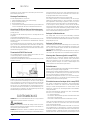 4
4
-
 5
5
-
 6
6
-
 7
7
-
 8
8
-
 9
9
-
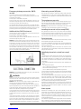 10
10
-
 11
11
-
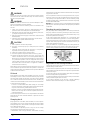 12
12
-
 13
13
-
 14
14
-
 15
15
-
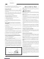 16
16
-
 17
17
-
 18
18
-
 19
19
-
 20
20
-
 21
21
-
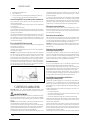 22
22
-
 23
23
-
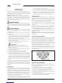 24
24
-
 25
25
-
 26
26
-
 27
27
-
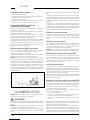 28
28
-
 29
29
-
 30
30
-
 31
31
-
 32
32
-
 33
33
-
 34
34
-
 35
35
-
 36
36
-
 37
37
-
 38
38
-
 39
39
-
 40
40
-
 41
41
-
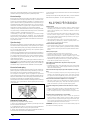 42
42
-
 43
43
-
 44
44
-
 45
45
-
 46
46
-
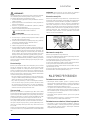 47
47
-
 48
48
-
 49
49
-
 50
50
-
 51
51
-
 52
52
-
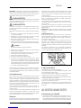 53
53
-
 54
54
-
 55
55
-
 56
56
-
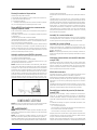 57
57
-
 58
58
-
 59
59
-
 60
60
-
 61
61
-
 62
62
-
 63
63
-
 64
64
-
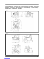 65
65
-
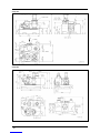 66
66
-
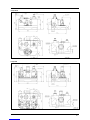 67
67
-
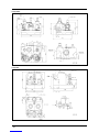 68
68
-
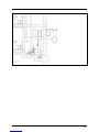 69
69
-
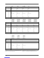 70
70
-
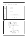 71
71
-
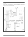 72
72
-
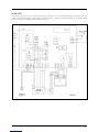 73
73
-
 74
74
-
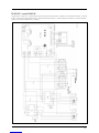 75
75
-
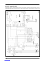 76
76
-
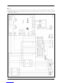 77
77
-
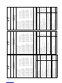 78
78
-
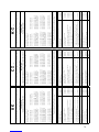 79
79
-
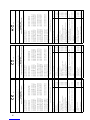 80
80
-
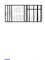 81
81
-
 82
82
-
 83
83
-
 84
84


Pentair Jung Pumpen Compli 400 E Instrukcja obsługi
- Typ
- Instrukcja obsługi
- Niniejsza instrukcja jest również odpowiednia dla
w innych językach
- italiano: Pentair Jung Pumpen Compli 400 E Manuale utente
- Deutsch: Pentair Jung Pumpen Compli 400 E Benutzerhandbuch
- slovenčina: Pentair Jung Pumpen Compli 400 E Používateľská príručka
- français: Pentair Jung Pumpen Compli 400 E Manuel utilisateur
- română: Pentair Jung Pumpen Compli 400 E Manual de utilizare
Inne dokumenty
-
Pentair 625-3 Instrukcja obsługi
-
 Kessel 016-307 Minilift S Überflur Installation and Operating Instructions
-
Pentair JUNG PUMPEN BAUFIX 100 Instrukcja obsługi
-
 Kessel 328-198 PS Aquapump Medium LW600 Installation and Operating Instructions
-
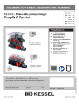 Kessel SPZ 1000 Instrukcja obsługi
-
DAB FEKABOX 110 Series Instruction For Installation And Maintenance
-
 Kessel 010-701 Technikschacht-LW1000 Installation and Operating Instructions
-
-
Biral Birox 90 Installation And Operating Instructions Manual
-
 Wita go.future-Z Instrukcja obsługi


