
You should read this user manual carefully before
using the appliance
Przed uruchomieniem urządzenia należy koniecznie
dokładnie przeczytać niniejszą instrukcję obsługi
User manual
Instrukcja obsługi
Item: 226865
226872
226667
226674
220726
220733
226889
226896
226773
226780
226902
226919
226926
226933
226940
226957
226964
226971
226988
226995
227046
227053
226766
226759
226735
226742
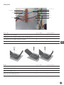
PIZZA OVEN
ELEKTRYCZNY PIEC DO PIZZY

Keep this manual with the appliance.
Zachowaj instrukcję urządzenia.
For indoor use only.
Do użytku wewnątrz pomieszczeń.
CONTENTS
1. SAFETY REGULATIONS ...........................................3
2. “CE” MARKING ........................................................5
3. TECHNICAL DESCRIPTIONS ...................................5
4. INSTALLATION ........................................................ 7
5. USE AND FUNCTIONING ....................................... 10
6. MAINTENANCE...................................................... 13
7. WARRANTY ............................................................ 14
8. DISCARDING & ENVIRONMENT ............................14
9. SPARE PARTS ........................................................ 14
10. ELECTRICAL DRAWINGS .......................................15
WARNING!
BEFORE SWITCHING ON THE OVEN:
REMOVE THE POLYSTYRENE.

3
EN
Dear Customer,
Thank you for purchasing this HENDI appliance. Please read this manual carefully before connecting the
appliance in order to prevent damage due to incorrect use. Read the safety regulations in particular very
carefully.
1. SAFETY REGULATIONS
• This appliance is intended for commercial use only and must not be used for
household use.
• The appliance must only be used for the purpose for which it was intended and
designed. The manufacturer is not liable for any damage caused by incorrect
operation and improper use.
• Keep the appliance and electrical plug away from water and any other liquids. In
the event that the appliance should fall into water, immediately remove plug from
the socket and do not use until the appliance has been checked by a certifi ed
technician. Failure to follow these instructions could cause a risk to lives.
• Never attempt to open the casing of the appliance yourself.
• Do not insert any objects in the casing of the appliance.
• Do not touch the plug with wet or damp hands.
• Danger of electric shock! Do not attempt to repair the appliance yourself. In case
of malfunctions, repairs are to be conducted by qualifi ed personnel only.
• Never use a damaged appliance! Disconnect the appliance from the electrical
outlet and contact the retailer if it is damaged.
• Warning! Do not immerse the electrical parts of the appliance in water or other
liquids. Never hold the appliance under running water.
•
Regularly check the power plug and cord for any damage. If the power plug or power
cord is damaged, it must be replaced by a service agent or similarly qualifi ed
persons in order to avoid danger or injury.
• Make sure the cord does not come in contact with sharp or hot objects and keep
it away from open fi re. To pull the plug out of the socket, always pull on the plug
and not on the cord.
• Ensure that the cord (or extension cord) is positioned so that it will not cause
a trip hazard.
• Always keep an eye on the appliance when in use.
• Warning! As long as the plug is in the socket the appliance is connected to the
power source.
• Turn off the appliance before pulling the plug out of the socket.

4
EN
• Never carry the appliance by the cord.
• Do not use any extra devices that are not supplied along with the appliance.
• Only connect the appliance to an electrical outlet with the voltage and frequency
mentioned on the appliance label.
• Connect the power plug to an easily accessible electrical outlet so that in case of
emergency the appliance can be unplugged immediately. To completely switch off
the appliance pull the power plug out of the electrical outlet.
• Always turn the appliance off before disconnecting the plug.
•
Never use accessories other than those recommended by the manufacturer. Fail-
ure
to do so could pose a safety risk to the user and could damage the appliance.
Only use original parts and accessories.
• This appliance is not intended for use by persons (including children) with reduced
physical, sensory or mental capabilities, or lack of experience and knowledge.
• This appliance must not be used by children under any circumstances.
• Keep the appliance and its cord out of reach of children.
• Always disconnect the appliance from the mains if it is left unattended or is not in
use, and before assembly, disassembly or cleaning.
• Never leave the appliance unattended during use.
• Before carrying out any kind of maintenance and/or adjustment intervention, it
is compulsory to disconnect the power supply by disconnecting the power supply
plug from the main socket verifying that the oven is effectively turned off and
cooled.

5
EN
2. “CE” MARKING
The “CE” marking consists of a gray lable applied on the back of the oven. The rating plate bears in a readable
and indelible way the following data:
3. TECHNICAL DESCRIPTIONS
The manufacturer and dealer is not liable for any
inaccuracies due to printing errors or transcrip-
tion, in this manual. In line with our policy of con-
tinuous improvement products, we reserve the
right to make modifi cation of the product, packag-
ing and specifi cations contained in the Documen-
tation without prior notice.
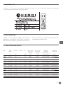
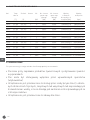
3.1 TECHNICAL DATA OVENS BASIC
Code Working
temperature
[˚C)
Power
supply
[V]
Chamber Power
[kW]
Power of top
heating
element
[kW]
Power of bottom
heating
element
[kW]
External
dimentions
without handles
[mm]
Internal
dimentions
[mm]
226865 50 | 320 230 1 1,6 800x1 800x1 567x427,5x(H)281 410x360x(H)90
226872 50 | 320 230 2 2,4 800x2 800x1 567x427,5x(H)428 410x360x(H)90
226667 50 | 320 230 1 1600 800x1 800x1 567x427,5x(H)281 410x360x(H)90
226674 50 | 320 230 2 2400 800x2 800x1 567x427,5x(H)428 2x 410x360x(H)90
220726 50 | 500 400 1 5000 2500x1 2500x1 915x621x(H)357 620x500x(H)120
220733 50 | 500 400 2 7500 2500x2 2500x1 915x621x(H)527 2x 620x500x(H)120
226889 50 | 500 230 | 400 1 5 2500x1 2500x1 915x621x(H)357 620x500x(H)120
226896 50 | 500 230 | 400 2 7,5 2500x2 2500x1 915x621x(H)527 620x500x(H)120
226773 50 | 500 230 | 400 1 4,7 2350x1 2350x1 975x924x(H)413 660x660x(H)140
226780 50 | 500 230 | 400 2 9,4 2350x2 2350x2 975x924x(H)745 660x660x(H)140
226902 50 | 500 230 | 400 1 7,2 1200x3 1200x3 975x1104x(H)413 660x990x(H)140
226919 50 | 500 230 | 400 2 14,4 1200x6 1200x6 975x1104x(H)745 660x990x(H)140

6
EN
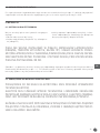
3.2 TECHNICAL DATA OVENS BASIC XL
Code Working
temperature
[˚C)
Power
supply
[V]
Chamber Power
[kW]
Power of top
heating
element
[kW]
Power of bottom
heating
element
[kW]
External
dimentions
without handles
[mm]
Internal
dimentions
[mm]
226926 50 | 500 230 | 400 1 6,0 3000x1 3000x1 1305x489x(H)413 1080x435x(H)140
226933 50 | 500 230 | 400 2 12 3000x2 3000x2 1305x489x(H)745 1080x435x(H)140
226940 50 | 500 230 | 400 1 6 3000x1 3000x1 1000x844x(H)413 720x720x(H)140
226957 50 | 500 230 | 400 2 12 3000x2 3000x2 1000x844x(H)745 720x720x(H)140
226964 50 | 500 230 | 400 1 9 1500x3 1500x3 1000x1204x(H)413 720x1080x(H)140
226971 50 | 500 230 | 400 2 18 1500x6 1500x6 1000x1204x(H)745 720x1080x(H)140
226988 50 | 500 230 | 400 1 9 1500x3 1500x3 1360x844x(H)413 1080x720x(H)140
226995 50 | 500 230 | 400 2 18 1500x6 1500x6 1360x844x(H)745 1080x720x(H)140
227046 50 | 500 230 | 400 1 13,2 2200x3 2200x3 1360x1204x(H)413 1080x1080x(H)140
227053 50 | 500 230 | 400 2 26,4 2200x6 2200x6 1360x1204x(H)745 1080x1080x(H)140
226766 50 | 500 400 1 6000 1000x3 1000x3 1000x844x(H)413 720x720x(H)140
226759 50 | 500 400 2 12000 1000x6 1000x6 1000x844x(H)745 2x 720x720x(H)140
226735 50 | 500 400 1 9000 1500x3 500x3 1000x1204x(H)413 720x1080x(H)140
226742 50 | 500 400 2 18000 1500x6 1500x6 1000x1204x(H)745 2x 720x1080x(H)140
3.3 DESTINATION OF USE
The oven has been designed and produced only for the following use:
• PIZZA BAKING, GRATINATING OF GASTRONOMY PRODUCTS AND HEATING OF
• FOODSTUFF IN BAKING PANS.
• THE OVEN CAN BE USED EXCLUSIVELY BY AUTHORIZED OPERATORS (USER).
• THIS APPLIANCE IS NOT INTENDED FOR USE BY PEOPLE (INCLUDING CHIL-
DREN) WITH REDUCED PHYSICAL, SENSORY OR MENTAL CAPABILITIES, OR
LACK OF EXPERIENCE AND KNOWLEDGE, UNLESS THEY HAVE BEEN GIVEN
SUPERVISION OR INSTRUCTION CONCERNING USE OF THE APPLIANCE BY
A PERSON RESPONSIBLE FOR THEIR SAFETY.
• CHILDREN SHOULD BE SUPERVISED TO ENSURE
THAT THEY DO NOT
PLAY WITH THE APPLIANCE

7
EN
3.4 LIMITS OF USE
This oven has been designed and manufactured exclusively for the destination of use described in Par. 3.3,
therefore, any other use is strictly forbidden in order to assure, at any time, the safety of the authorized operators,
as well as the effi ciency of the oven itself.
4. INSTALLATION
4.1 INSTRUCTIONS FOR THE USER
The place where the oven is installed must have the
following enviromental features:
• To be dry;
• Water sources at safe distance;
• Adequate ventilation and lighting corresponding
to hygene and security rules following the exist-
ing laws.
THE OVEN MUST NOT BE INSTALLED IN PROXIMITY OF THE FLAMMABLE MA-
TERIALS (WOODS, PLASTIC, COMBUSTIBLE, GAS, ETC.). AVOID THE CONTACT OF
FLAMMABLE OBJECTS WITH THE HOT SURFACES OF THE OVEN. ALWAYS ASSURE
THE SAFETY FIREPROOF CONDITIONS. MAINTAIN A FREE SPACE AROUND THE
OVEN OF AT LEAST 30 CM.
Check that the electrical data of the user’s electric system corresponds to the equipment requirements
stated on the rating plate and on the above technical characteristics Par. 3.1, 3.2, The characteristics
of the electric socket must be compatible with the plug installed on the cable.
4.2 ELECTRIC CONNECTION
THE CONNECTION TO THE POWER SUPPLY MUST BE EXCLUSIVELY CARRIED OUT
BY AN AUTHORIZED TECHNICIAN (ELECTRICIAN) SATISFYING THE TECHNICAL
AND PROFESSIONAL REQUIREMENTS STATED BY THE REGULATIONS IN FORCE
IN THE COUNTRY OF USE , THIS TECHNICIAN MUST ISSUE A DECLARATION OF
CONFORMITY FOR THE INTERVENTION PERFORMED.
THE MAIN LINE SHOULD BE EQUIPPED WITH SAFETY DEVICES BY A DIFFEREN-
TIAL SWITCH / CICUIT BRAKER, CO-ORDINATED WITH THE GENERAL EARTH IN-
STALLATION, IN CONFORMITY WITH THE LOCAL AND NATIONAL LAWS.

8
EN
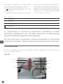
To connect the machine to the electric network it is
necessary to proceed as follows:
• connect to the wires to the terminals L1—L2—
L3—N — of power cord type H07RNF 3G X “x” mm²
unsheathed with ferule;
• put together the other end of the cable and a plug,
which is normalised and polarised (the distinction
between phase and neutral must be unequivocal.
• to connect the oven to 230 V single phase is suf-
fi cient to make a bridge between L1-L2-L3 with
the special plates present in the terminal box
L1 Clamp N.1
L2 Clamp N.2
L3 Clamp N.3
N Clamp N. 4 o N. 5
Clamp N. 6
ONCE THE ELECTRIC CONNECTION HAS BEEN COMPLETED, THE AUTHORIZED
TECHNICIAN (ELECTRICIAN) MUST ISSUE A DECLARATION CERTIFYING THE
MEASUREMENT OF THE CONTINUITY OF THE EQUIPOTENTIAL PROTECTION
CIRCUIT.
THE APPLIANCE IS TO BE SUPPLIED THROUGH A RESIDUAL CURRENT DEVICE
(RCD) HAVING A RATED RESIDUAL OPERATING CURRENT NOT EXCEEDING 30 MA
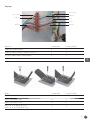
4.3 TERMINAL
The terminal box is placed externally on the back of the oven.
Single phase
yellow/green
yellow/green
blue
blue
brown
brown

9
EN
Three phase
yellow/green
yellow/green
blue
blue
grey
black
brown brown
Oven type N. of cables Section (mm²)
Single phase, one chamber 3 4
Single phase, two chambers and versions 9 single phase 3 6
Three phase one chamber and two chambers 5 4
Three phase from versions 9 and up 5 6
Model N. of cables Section (mm²)
BASIC 1/40; BASIC 2/40 3 2,5
BASIC 1/50; BASIC 2/50 5 4
BASIC 4-44; BASIC 6-66 5 4
BASIC XL 4-44; BASIC XL 6-66;
BASIC XL 6L-66L; BASIC XL 9-99
55

10
EN
4.5 EQUIPOTENTIAL
The equipment must be connected with an equi-potential device the connection terminal is located near the
terminal box. The bonding wire must have a minimal section of 10 mm².
5. USE AND FUNCTIONING
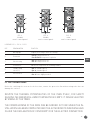
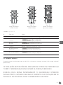
5.1 CONTROL PANEL
The control panel is installed on the front of the oven as shown in FIG. 1,2,3.
PIC. 1
226865
oven’s control panel
PIC. 2
226872
oven’s control panel
LEGEND PIC.1 - PIC.2
REF. DENOMINATION FUNCTION
1 Warning light If lighted, the heating elements are working
1/a Warning light If lighted, timer is on
2 Thermostat
• Pos. 0: the heating elements are off
• Pos. 50-320°C: temperature regulation
6 Timer It adjusts the cooking time
7 General switch Turns all the devices off

11
EN
00
0
50
100
150
200
250
300
350
400
450
500
50
100
150
200
250
300
350
400
450
500
1
1
5
4
2
2
8
0
1
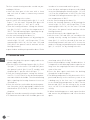
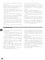
PIC. 3
226889
oven’s control panel
PIC. 4
226889
oven’s control panel
PIC. 5
other
oven’s control panel
LEGEND PIC.3 - PIC.4 - PIC.5
REF. DENOMINATION FUNCTION
1 Warning light If lighted, the heating elements are working.
2 Thermostat
• Pos. 0: heating elements off;
• Pos. 50-500°C: temperature regulation.
3 Switch heating
• Pos. I: heating elements on;
• Pos. 0: heaing elements off.
4 Thermometer Indicates the temperature in the baking chamber.
5
Chamber lamp
switch (I-0)
• Pos. I: chamber light on;
• Pos. 0: chamber light off.
8 General switch
• Pos. I: Power supply turned on;
• Pos. 0: Power supply turned off.
5.2 FIRST COMMISSIONING
Before the switching the oven on for the fi rst time, remove the protective fi lm without using tools that can
damage the surfaces.
DESPITE THE THERMAL POTENTIALITIES OF THE OVEN ITSELF, FOR SAFETY
REASONS THE MAXIMUM ALLOWED TEMPERATURE IS 500°C. IT CAN BE SELECTED
BY MEANS OF THE TIMER.
THE COMMISSIONING OF THE OVEN CAN BE CARRIED OUT ONLY WHEN THE IN-
STALLATION HAS BEEN COMPLETED AND THE AUTHORIZED TECHNICIANS HAVE
ISSUED THE DECLARATION OF CONFORMITY FOR THE ELECTRIC CONNECTION.

12
EN
The fi rst commissioning must be carried out pro-
ceeding as follows:
• clean the front part of the oven with a clean
and soft cloth in order to remove any eventual
residues;
• connect the plug to the socket;
• put the switch of heating elements (pic.3; 4 – ref.3)
in pos.”i”; for the ovens 1/40 and 2/40: press the
general switch (pic.1;2 - ref.7; pic.5 - ref.8);
• Start the heating elements setting the thermo-
stat (pic.1;2;3;4;5 - ref.2) on the temperature of
150°C. The red warning lights signaling the op-
eration of the heating elements is on;
• let the oven heating up for about 1 h;
• switch the heating elements off by putting the
switch in (pic.1;2;3;4;5 - ref.2) in position “0” the
warning light turns off; for the oven 1/40 and
2/40: press the general switch and turn off the
heating elements;
• open the door and keep it opened for about 15 min
in order to let steam and smell to go out;
• close the door and repeat the process described
in section 4) bringing the thermostat (pic. 1;2;3;4;5
- rif.2)
at the temperature of 400°C for the oven
1/40 and 2/40: bring thermostats (pic.1;2 - ref.2)
at a temperature of 350°C.
• let the oven heating up for about 1 h;
• switch the heating elements off by putting the
switch in (pic.1;2;3;4;5 - ref.2) in position “0” the
warning light turns off; for the oven 1/40 and
2/40: press the general switch and turn off the
heating elements;
• turn off the oven as described in par. 5.4
• with the oven 1/40 and 2/40 you can adjust the
cooking time by setting the minutes with the
timer (pic.1;2 - ref.6). at the end of the time set
the heating elements will turn off. To choose the
mode of cooking continued, bring the timer knob
(pic.1;2 - ref.6) to “on” by turning to the left
5.3 TURNING ON OVEN
1. Connect the plug of the power supply cable to the
power supply outlet;
2. Put the switch of heating elements (pic.3;4;5-ref.
3) in pos.”i”; for the ovens 1/40 and 2/40: press
the general switch (pic.1;2-ref.7), models with
the panel pic.5 - put the switch 8 in pos. “I”;
3. Start the heating elements setting the thermo-
stat (Pic.1;2;3;4;5-Ref.2) to the desired tempera-
ture indicated on the handle. The related warning
lights signaling the heating elements in use are
switched on;
4. Once the oven has reached the desired tempera-
ture (see point 9 of this paragraph), visible on the
thermometer (Pic.5-Ref.4), it is possible to insert
the pizza;
5.Open the oven door manually using the handles;
6. To illuminate the inside of the chamber, press the
oven lamp switch (Pic.5-Ref.5);
7. Insert the pizza/pizzas using suitable devices. It
is important to avoid leaving the door open for too
long, since the outgoing heat lowers the temper-
ature of the oven.
8. Close the door again and check the backing
through the inspection glass ;
9. The baking temperature of the pizza varies if it is
positioned directly on the refractory stone or on
a baking tray. In the fi rst case, it is suggested
to set the backing temperature at 280°C on the
bottom and 320°C for the ceiling; in the second
case, set 320°C for the bottom and 280°C for the
ceiling;
10. When the baking process ends, open the door
and extract the pizza/pizzas and colse the door
again.

13
EN
5.4 TURNING OFF THE OVEN
Once the cooking/backing process is over, please proceed as follows:
Turn the oven off by putting the switches of heating elements in pos.”0” (Pic.3;4;5-Rif.3) and the knobs that
regulate the thermostats (Pic.1;2;3;4;5-Ref.2);
For the ovens 1/40 and 2/40: press the general switch and turn off the heating elements;
For the ovens with the panel pic.5 - put the switch 8 in pos. “0”;
For all ovens - disconnect the power supply using main external wall switch;
Do not leave the oven unattended under voltage.
6. MAINTENANCE
BEFORE CARRING OUT ANY TYPE OF MAINTENANCE INTERVENTION, IT IS COM-
PULSORY TO DISCONNECT THE PLUG FROM THE MAIN POWER SUPPLY.
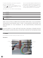
6.1 CLEANING
The clearing must be carried out after every use
following the instructions.
Cleaning of the refractory surface: this operation
has to be done with hot oven.
Once the temperature is about 350°C, turn the
oven off, open the door and clean the surface using
a brush in vegetable fiber equipped with a long
handle in order to avoid the contact with the oven
hot parts.
External clearing: (surfaces in stainless steel, in-
spection glass and control panel): this operation
has to be done with cold oven.
IT IS RECOMMENDED TO USE PROPER GLOVES AND SUITABLE CLOTHING TO
AVOID BURNINGS.
IT IS FORBIDDEN TO USE THROWS OR DRIPS OF WATER, ABRASIVE OR COR-
ROSIVE SUBSTANCES, AND ANYTHING ELSE THAT CAN DAMAGE THE COMPO-
NENTS, COMPROMISE THE SAFETY, AND BE DANGEROUS FROM AN HYGIENIC
POINT OF VIEW.
For any emergency maintenance, repairing and/
or replacement refer exclusively to the authorized
dealer where the oven has been bought and/or to
an authorized technician satisfying the technical
and professional requirements stated by the reg-
ulations in force.

14
EN
7. WARRANTY
Any defect affecting the functionality of the ap-
pliance which becomes apparent within one year
after purchase will be repaired by free repair or re-
placement provided the appliance has been used
and maintained in accordance with the instructions
and has not been abused or misused in any way.
Your statutory rights are not affected. If the appli-
ance is claimed under warranty, state where and
when it was purchased and include proof of pur-
chase (e.g. receipt).
In line with our policy of continuous product devel-
opment we reserve the right to change the product,
packaging and documentation specifi cations with-
out notice.
8. DISCARDING & ENVIRONMENT
At the end of the life of the appliance, please dispose
of the appliance according to the regulations and
guidelines applicable at the time.
Throw packing materials like plastic and boxes in the
appropriate containers.
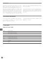
9. SPARE PARTS
SPARE PARTS BASIC OVENS
MARK DESCRIPTION
T Single (1) pole thermostat
TT Three (3) poles thermostat
QS0 Heating elements on/off switch
HL Heating elements spy light
QF0/1 Chamber light on/off switch
K Contactor
TI Timer

15
EN
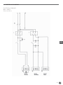
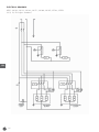
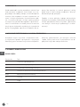
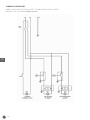
10. ELECTRICAL DRAWINGS
ELECTRICAL DRAWINGS
MOD.: 226872
230 V, 1N, 50 Hz

16
EN
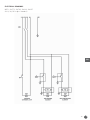
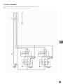
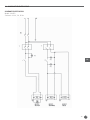
ELECTRICAL DRAWINGS
MOD.: 226896
400 V, 3N, 50 Hz

17
EN
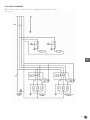
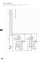
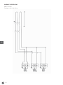
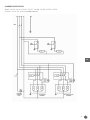
ELECTRICAL DRAWINGS
MOD.: 226773, 226780, 226940, 226957
400 V, 3N, 50 Hz (per chamber)

18
EN
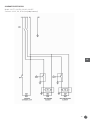
ELECTRICAL DRAWINGS
MOD.: 226902, 226919, 226964, 226971, 226988, 226995, 227046, 227053
230, 1N, 50 Hz (per chamber)

19
EN
ELECTRICAL DRAWINGS
MOD.: 226902, 226919, 226964, 226971, 226988, 226995, 227046, 227053
400 V, 3N, 50 Hz (per chamber)

20
EN
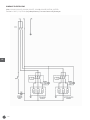
ELECTRICAL DRAWINGS
MOD.: 226902, 226919, 226964, 226971, 226988, 226995, 227046, 227053
230 V, 1N, 50 Hz (per chamber)
Strona jest ładowana ...
Strona jest ładowana ...
Strona jest ładowana ...
Strona jest ładowana ...
Strona jest ładowana ...
Strona jest ładowana ...
Strona jest ładowana ...
Strona jest ładowana ...
Strona jest ładowana ...
Strona jest ładowana ...
Strona jest ładowana ...
Strona jest ładowana ...
Strona jest ładowana ...
Strona jest ładowana ...
Strona jest ładowana ...
Strona jest ładowana ...
Strona jest ładowana ...
Strona jest ładowana ...
Strona jest ładowana ...
Strona jest ładowana ...
Strona jest ładowana ...
Strona jest ładowana ...
Strona jest ładowana ...
Strona jest ładowana ...
Strona jest ładowana ...
Strona jest ładowana ...
Strona jest ładowana ...
Strona jest ładowana ...
-
 1
1
-
 2
2
-
 3
3
-
 4
4
-
 5
5
-
 6
6
-
 7
7
-
 8
8
-
 9
9
-
 10
10
-
 11
11
-
 12
12
-
 13
13
-
 14
14
-
 15
15
-
 16
16
-
 17
17
-
 18
18
-
 19
19
-
 20
20
-
 21
21
-
 22
22
-
 23
23
-
 24
24
-
 25
25
-
 26
26
-
 27
27
-
 28
28
-
 29
29
-
 30
30
-
 31
31
-
 32
32
-
 33
33
-
 34
34
-
 35
35
-
 36
36
-
 37
37
-
 38
38
-
 39
39
-
 40
40
-
 41
41
-
 42
42
-
 43
43
-
 44
44
-
 45
45
-
 46
46
-
 47
47
-
 48
48


Hendi 226896 Instrukcja obsługi
- Kategoria
- Mikrofale
- Typ
- Instrukcja obsługi
w innych językach
- English: Hendi 226896 User manual
