Indesit CX65SF9 X U /HA instrukcja
- Kategoria
- Piekarniki
- Typ
- instrukcja

GB
COOKER AND OVEN
CX65SF9 U/HA
CX65SF9 X U/HA
Contents
Installation, 2-5
Positioning and levelling
Electrical connection
Gas connection
Adapting to different types of gas
Table of burner and nozzle specifications
Table of characteristics
Description of the appliance, 6
Overall view
Control panel
Display
Start-up and use, 7-11
Using the hob
Setting the clock
Setting the timer
Using the oven
Cooking modes
Programming cooking
Practical cooking advice
Cooking advice table
Precautions and tips, 12
General safety
Disposal
Respecting and conserving the environment
Care and maintenance, 13-14
Switching the appliance off
Cleaning the appliance
Replacing the oven light bulb
Gas tap maintenance
Automatic cleaning using the FAST CLEAN function
Assistance, 15
Operating Instructions
Polski, 16
GB
English,1
PL

2
GB
Before operating your new appliance please read
this instruction booklet carefully. It contains
important information concerning the safe installation
and operation of the appliance.
Please keep these operating instructions for future
reference. Make sure that the instructions are kept
with the appliance if it is sold, given away or moved.
The appliance must be installed by a qualified
professional according to the instructions provided.
Any necessary adjustment or maintenance must be
performed after the cooker has been disconnected
from the electricity supply.
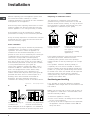
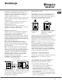
Room ventilation
The appliance may only be installed in permanently-
ventilated rooms, according to current national
legislation. The room in which the appliance is
installed must be ventilated adequately so as to
provide as much air as is needed by the normal gas
combustion process (the flow of air must not be
lower than 2 m
3
/h per kW of installed power).
The air inlets, protected by grilles, should have a
duct with an inner cross section of at least 100 cm
2
and should be positioned so that they are not liable
to even partial obstruction (see figure A).
These inlets should be enlarged by 100% - with a
minimum of 200 cm
2
- whenever the surface of the
hob is not equipped with a flame failure safety
device. When the flow of air is provided in an
indirect manner from adjacent rooms (see figure B),
provided that these are not communal parts of a
building, areas with increased fire hazards or
bedrooms, the inlets should be fitted with a
ventilation duct leading outside as described above.
Adjacent room Room requiring ventilation
AB
A
Ventilation opening for Increase in the gap between
comburent air the door and the flooring
After prolonged use of the appliance, it is advisable to
open a window or increase the speed of any fans used.
Disposing of combustion fumes
The disposal of combustion fumes should be
guaranteed using a hood connected to a safe and
efficient natural suction chimney, or using an electric
fan that begins to operate automatically every time
the appliance is switched on (see figure).
Fumes channelled Fumes channelled through
straight outside a chimney or a branched
flue system
(reserved for cooking
appliances)
The liquefied petroleum gases are heavier than air
and collect by the floor, therefore all rooms
containing LPG cylinders must have openings
leading outside so that any leaked gas can escape
easily.
LPG cylinders, therefore, whether partially or
completely full, must not be installed or stored in
rooms or storage areas that are below ground level
(cellars, etc.). Only the cylinder being used should
be stored in the room; this should also be kept well
away from sources of heat (ovens, chimneys,
stoves) which may cause the temperature of the
cylinder to rise above 50°C.
Positioning and levelling
It is possible to install the appliance alongside
cupboards whose height does not exceed that of the
hob surface.
Make sure that the wall in contact with the back of
the appliance is made from a non-flammable, heat-
resistant material (T 90°C).
To install the appliance correctly:
Place it in the kitchen, the dining room or the bed-
sit (not in the bathroom).
If the top of the hob is higher than the cupboards,
the appliance must be installed at least 600 mm
away from them.
Installation

GB
3
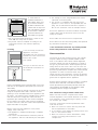
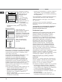
If the cooker is
installed underneath a
wall cabinet, there must
be a minimum distance
of 420 mm between this
cabinet and the top of the
hob. This distance should
be increased to 700 mm
if the wall cabinets are
flammable (see figure).
Do not position blinds behind the cooker or less
than 200 mm away from its sides.
Any hoods must be installed according to the
instructions listed in the relevant operating
manual.
Levelling
If it is necessary to level the
appliance, screw the
adjustable feet into the places
provided on each corner of the
base of the cooker
(see figure).
The legs* fit into the slots on
the underside of the base of
the cooker.
Electrical connection
Install a standardised plug corresponding to the load
indicated on the appliance data plate (see Technical
data table).
The appliance must be directly connected to the mains
using an omnipolar switch with a minimum contact
opening of 3 mm installed between the appliance and
the mains. The switch must be suitable for the charge
indicated and must comply with current electrical
regulations (the earthing wire must not be interrupted
by the switch). The supply cable must be positioned
so that it does not come into contact with temperatures
higher than 50°C at any point.
Before connecting the appliance to the power
supply, make sure that:
The appliance is earthed and the plug is compliant
with the law.
The socket can withstand the maximum power of
the appliance, which is indicated by the data plate.
HOOD
420
Min.
min. 650 mm. with hood
min.
700 mm. without hood
mm.
600
Min. mm.
420
Min. mm.
The voltage is in the range between the values
indicated on the data plate.
The socket is compatible with the plug of the
appliance. If the socket is incompatible with the
plug, ask an authorised technician to replace it.
Do not use extension cords or multiple sockets.
Once the appliance has been installed, the power
supply cable and the electrical socket must be
easily accessible.
The cable must not be bent or compressed.
The cable must be checked regularly and replaced
by authorised technicians only.
The manufacturer declines any liability should
these safety measures not be obs erved.
Gas connection
Connection to the gas network or to the gas cylinder
may be carried out using a flexible rubber or steel
hose, in accordance with current national legislation
and after making sure that the appliance is suited to
the type of gas with which it will be supplied (see the
rating sticker on the cover: if this is not the case see
below). When using liquid gas from a cylinder, install a
pressure regulator which complies with current national
regulations. To make connection easier, the gas
supply may be turned sideways*: reverse the position
of the hose holder with that of the cap and replace the
gasket that is supplied with the appliance.
Check that the pressure of the gas supply is consistent
with the values indicated in the Table of burner and
nozzle specifications (see below). This will ensure the
safe operation and durability of your appliance while
maintaining efficient energy consumption.
Gas connection using a flexible rubber hose
Make sure that the hose complies with current
national legislation. The internal diameter of the hose
must measure: 8 mm for liquid gas supply; 13 mm
for methane gas supply.
Once the connection has been performed, make
sure that the hose:
Does not come into contact with any parts that
reach temperatures of over 50°C.
Is not subject to any pulling or twisting forces and
that it is not kinked or bent.
Does not come into contact with blades, sharp
corners or moving parts and that it is not
compressed.

4
GB
Is easy to inspect along its whole length so that
its condition may be checked.
Is shorter than 1500 mm.
Fits firmly into place at both ends, where it will be
fixed using clamps which comply with current
regulations.
If one or more of these conditions is not fulfilled or
if the cooker must be installed according to the
conditions listed for class 2 - subclass 1 appliances
(installed between two cupboards), the flexible steel
hose must be used instead (see below).
Connecting a flexible jointless stainless steel
pipe to a threaded attachment
Make sure that the hose and gaskets comply with
current national legislation.
To begin using the hose, remove the hose holder on
the appliance (the gas supply inlet on the appliance
is a cylindrical threaded 1/2 gas male attachment).
Perform the connection in such a way that the hose
length does not exceed a maximum of 2 metres,
making sure that the hose is not compressed and
does not come into contact with moving parts.
Checking the tightness of the connection
When the installation process is complete, check the
hose fittings for leaks using a soapy solution. Never
use a flame.
Adapting to different types of gas
It is possible to adapt the appliance to a type of gas
other than the default type (this is indicated on the
rating label on the cover).
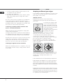
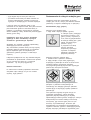
Adapting the hob
Replacing the nozzles for the hob burners:
1. Remove the hob grids and slide the burners off
their seats.
2. Unscrew the nozzles using
a 7 mm socket spanner (see
figure), and replace them with
nozzles suited to the new type
of gas (see Burner and nozzle
specifications table).
3. Replace all the components
by following the above
instructions in reverse.
Adjusting the hob burners minimum setting:
1. Turn the tap to the minimum position.
2. Remove the knob and adjust the regulatory
screw, which is positioned inside or next to the tap
pin, until the flame is small but steady.
If the appliance is connected to a liquid gas
supply, the regulatory screw must be fastened as
tightly as possible.
3. While the burner is alight, quickly change the position
of the knob from minimum to maximum and vice versa
several times, checking that the flame is not
extinguished.
The hob burners do not require primary air adjustment.
After adjusting the appliance so it may be used with a
different type of gas, replace the old rating label with a
new one that corresponds to the new type of gas (these
labels are available from Authorised Technical Assistance
Centres).
Should the gas pressure used be different (or vary
slightly) from the recommended pressure, a suitable
pressure regulator must be fitted to the inlet hose in
accordance with current national regulations relating
to regulators for channelled gas.

GB
5
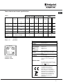
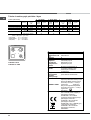
Table of burner and nozzle specifications
Table 1
Natural Gas GZ 50 Natural Gas GZ 35 GPB-B
Burner Diameter
(mm)
Thermal power
(p.c.i.*)
Nozzle
1/100
Flow*
l/h
Nozzle
1/100
Flow*
l/h
Thermal
power
(p.c.i.*)
Nozzle
1/100
Flow*
g/h
kW (mm) (mm) kW (mm)
Fast
(Large)(R)
100 2,70 116 285 183 398 2,70 86 225
Semi Fast
(Medium)(S)
75 1,70 106 180 143 251 1,70 70 142
Auxiliary
(Small)(A)
55 0,90 79 95 106 133 0,90 50 75
Triple Ring (TC) 130 3,00 133 317 197 442 3,00 91 250
Supply
Pressures
Nominal (mbar)
Minimum (mbar)
Maximum (mbar)
16
20
25
10
13
16
29
36
44
* A 0°C e 1013 mbar-dry gas
GZ 50 p.c.i. 35.9 MJ/m
³
GZ 35 p.c.i. 25.8 MJ/m³
GPB-B p.c.i. 123.6 MJ/m³
TC
A
S
R
CX65SF9 U/HA
CX65SF9 X U/HA
TABLE OF CHARACTERISTICS
Oven dimensions
(HxWxD)
32x43.5x40 cm
Volume
56 l
Useful
measurements
relating to the
oven
compartment
width 42 cm
depth 44 cm
height 8.5 cm
Burners
may be adapted for use with any
type of gas shown on the data
plate
Voltage and
frequency
see data plate
ENERGY LABEL
Directive 2002/40/EC on the label
of electric ovens. Standard EN
50304
Declared energy consumption for
Forced convection Class heating
mode: Gratin
EC Directives: 2006/95/EEC dated
12/12/06 (Low Voltage) and
subsequent amendments -
89/336/EEC dated 03/05/89
(Electromagnetic Compatibility)
and subsequent amendments -
90/369/EEC dated 29/06/90 (Gas)
and subsequent amendments -
93/68/EEC dated 22/07/93 and
subsequent amendments -
2002/96/EC.

6
GB
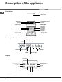
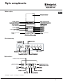
Description of the appliance
Overall view
Control panel
Hob grid
Glass co
ver*
Control
panel
GRILL rack
DRIPPING PAN rack
GUIDE RAILS
for the sliding racks
position
3
position
2
position
1
Gas b
urner
Containment surface
for
spills
Adjustable f
oot
Adjustable f
oot
position
5
position 4
*
Only available in certain models.
THERMOSTAT
knob
DISPLAY
Hob BURNER
control knobs
SELECTOR
Knob
TIME SETTING
button
FAST CLEAN
button
TIMER
knob
Display
END OF COOKING
icon
CLOCK
icon
TEMPERATURE and
TIME digits
DURATION
icon
TIMER
icon
STOP
icon
Recommended rack
position icon
Preheating
indicator
DOOR LOCK
indicator

GB
7
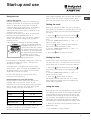
Start-up and use
Using the hob
Lighting the burners
For each BURNER knob there is a complete ring
showing the strength of the flame for the relevant
burner. To light one of the burners on the hob:
1. Bring a flame or gas lighter close to the burner.
2. Press the BURNER knob and turn it in an
anticlockwise direction so that it is pointing to the
maximum flame setting.
3. Adjust the intensity of the flame to the desired
level by turning the BURNER knob in an
anticlockwise direction. This may be the minimum
setting, the maximum setting or any position in
between the two.
If the appliance is fitted with an electronic lighting
device* (see figure), press the
BURNER knob and turn it in an
anticlockwise direction, towards
the minimum flame setting, until
the burner is lit. The burner may
be extinguished when the knob
is released. If this occurs,
repeat the operation, holding
the knob down for a longer period of time.
If the flame is accidentally extinguished, switch off
the burner and wait for at least 1 minute before
attempting to relight it.
If the appliance is equipped with a flame failure
safety device*, press and hold the BURNER knob
for approximately 2-3 seconds to keep the flame
alight and to activate the device.
To switch the burner off, turn the knob until it
reaches the stop position .
Practical advice on using the burners
For the burners to work in the most efficient way
possible and to save on the amount of gas
consumed, it is recommended that only pans which
have a lid and a flat base are used. They should
also be suited to the size of the burner.
Burner ø Cookware Diameter (cm)
Fast (R) 24 - 26
Semi Fast (S) 16 - 20
Auxiliary (A) 10 - 14
Triple Crown (TC) 24 - 26
To identify the type of burner, please refer to the
diagrams contained in the paragraph entitled
Burner and nozzle specifications.
For models equipped with a reducer grid, the latter
must be used only for the auxiliary burner, when
pans with a diameter of less than 12 cm are used.
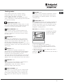
Setting the clock
The clock may be set when the oven is switched
off or when it is switched on, provided that a the end
time of a cooking cycle has not been programmed
previously.
1. Press the button several times until the
icon and the first two digits on the display start to
flash.
2. Turn the TIMER KNOB towards + and - to
adjust the hour value.
3. Press the
button again until the other two
digits on the DISPLAY begin to flash.
4. Turn the TIMER KNOB towards + and - to
adjust the minute value.
5. Press the
button again to confirm.
Setting the timer
This function does not interrupt cooking and does
not affect the oven; it is simply used to activate the
buzzer when the set amount of time has elapsed.
1. Press the
button several times until the
icon and the three digits on the display begin to
flash.
2. Turn the TIMER KNOB towards + and - to
adjust the minute value.
3. Press the
button again to confirm.
The display will then show the time as it counts
down. When this period of time has elapsed the
buzzer will be activated.
Using the oven
The first time you use your appliance, heat the empty
oven with its door closed at its maximum temperature
for at least half an hour. Ensure that the room is well
ventilated before switching the oven off and opening
the oven door. The appliance may emit a slightly
unpleasant odour caused by protective substances
used during the manufacturing process burning away.
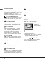
1. Select the desired cooking mode by turning the
SELECTOR knob.
*
Only available in certain models.

8
GB
2. The oven begins its preheating stage and the
preheating indicator lights up.
The temperature may be changed by turning the
THERMOSTAT knob
3. When the preheating indicator
switches off
and a buzzer sounds the preheating process is
complete: you may now place the food in the oven.
4. The DISPLAY will show the icon
, which
indicates the recommended shelf level for the tray.
5. During cooking it is always possible to:
- change the cooking mode by turning the
SELECTOR knob
- change the temperature by turning the
THERMOSTAT knob
- set the cooking duration and the end cooking time
(see Cooking Modes)
- stop cooking by turning the SELECTOR knob to the
0 position.
6. The oven switches off automatically after two
hours: this default period of time is set for all
cooking modes for safety reasons.
The cooking time may be modified (see Cooking
Modes).
7. If a blackout occurs while the oven is already in
operation, an automatic system within the appliance
will reactivate the cooking mode from where it was
interrupted as long as the temperature has not
dropped below a certain level. Programmed cooking
modes which have not started will not be restored
and must be reprogrammed.
! There is no preheating stage for the BARBECUE
mode.
! Never put objects directly on the bottom of the
oven; this will avoid the enamel coating being
damaged.
! Always place cookware on the rack(s) provided.
Cooling ventilation
In order to cool down the external temperature of the oven,
a cooling fan blows a stream of air between the control
panel and the oven door. At the beginning of the FAST
CLEAN mode, the cooling fan operates at low
speed.
Once cooking has been completed, the cooling fan
remains on until the oven has cooled down sufficiently.
Oven light
When the oven is not in operation, the lamp can be
switched on at any time by opening the oven door.

GB
9
Cooking modes
! All cooking modes have a default cooking
temperature which may be adjusted manually
between 40°C and 250°C as desired.
In the BARBECUE mode, the default power level
value is indicated as a percentage (%) and may also
be adjusted manually.
TRADITIONAL OVEN mode
When using this traditional cooking mode, it is best
to use one cooking rack only. if more than one rack
is used, the heat will be distributed unevenly.
MULTI-COOKING mode
Since the heat remains constant throughout the
oven, the air cooks and browns food in a uniform
manner. A maximum of two racks may be used at
the same time.
BARBECUE mode
By turning the THERMOSTAT knob, the different
power levels which may be set will appear on the
display; these range between 50% and 100%. The
high and direct temperature of the grill is
recommended for food which requires a high surface
temperature. Always cook in this mode with the oven
door closed.
GRATIN mode
This combination of features increases the
effectiveness of the unidirectional thermal radiation
provided by the heating elements through forced
circulation of the air throughout the oven.
This helps prevent food from burning on the surface
and allows the heat to penetrate right into the food.
Always cook in this mode with the oven door closed.
PROVING mode
The oven reaches and maintains a temperature of
40°C irrespective of the position of the
THERMOSTAT knob. This mode is ideal for
leavening dough made with yeast.
FAST COOKING mode
Preheating is not necessary for this cooking mode.
This mode is particularly suitable for cooking pre-
packed food quickly (frozen or pre-cooked). The
best results are achieved using one cooking rack
only.
BAKING mode
This mode is ideal for baking temperature sensitive
foods (such as cakes, which need to rise) and for
the preparation of bitesize pastries on 3 shelves
simultaneously.
PIZZA OVEN mode
This combination heats the oven rapidly by producing
a considerable amount of heat, particularly from the
element at the bottom. If you use more than one rack
at a time, switch the position of the dishes halfway
through the cooking process.
Spit r oast (only available in certain models)
To operate the spit roast
function (see diagram)
proceed as follows:
1. Place the dripping pan in position 1.
2. Place the rotisserie support in position 3 and
insert the spit in the hole provided on the back
panel of the oven.
3. Start the rotisserie using the SELECTOR knob to
select mode
or .
! When the mode is activated, the spit will stop if
the door is opened.

10
GB
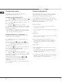
Programming cooking
A cooking mode must be selected before
programming can take place.
Programming the cooking duration
1. Press the
button several times until the
icon and the three digits on the DISPLAY begin to
flash.
2. Turn the TIMER KNOB towards + and - to
adjust the duration.
3. Press the
button again to confirm.
4. When the set time has elapsed, the text END
appears on the DISPLAY, the oven will stop cooking
and a buzzer sounds.
For example: it is 9:00 a.m. and a time of 1 hour
and 15 minutes is programmed. The programme
will stop automatically at 10:15 a.m.
Setting the end time for a cooking mode
A cooking duration must be set before the end
cooking time can be scheduled.
1. Follow steps 1 to 3 to set the duration as
detailed above.
2. Next, press the
button until the icon
and the two digits on the DISPLAY begin to flash.
3. Turn the TIMER KNOB towards + and - to
adjust the hour value.
4. Press the
button again until the other two
digits on the DISPLAY begin to flash.
5. Turn the TIMER KNOB towards + and - to
adjust the minute value.
6. Press the
button again to confirm.
7. When the set time has elapsed, the text END
appears on the DISPLAY, the oven will stop cooking
and a buzzer sounds.
Programming has been set when the
and
buttons are illuminated. The DISPLAY shows the
cooking end time and the cooking duration
alternately.
To cancel programming, turn the SELECTOR knob to
the 0 position.
Practical cooking advice
! Do not place racks in position 1 and 5 during fan-
assisted cooking. This is because excessive direct
heat can burn temperature sensitive foods.
! In the BARBECUE and GRATIN cooking modes,
particularly when using the rotisserie spit, place the
dripping pan in position 1 to collect cooking
residues (fat and/or grease).
MULTI-COOKING
Use positions 2 and 4, placing the food which
requires more heat on 2.
Place the dripping pan on the bottom and the rack
on top.
BARBECUE
Place the rack in position 3 or 4. Position the food
in the centre of the rack.
We recommend that the power level is set to
maximum. The top heating element is regulated
by a thermostat and may not always operate
constantly.
PIZZA OVEN
Use a light aluminium pizza pan. Place it on the
rack provided.
For a crispy crust, do not use the dripping pan as
it prevents the crust from forming by extending
the total cooking time.
If the pizza has a lot of toppings, we recommend
adding the mozzarella cheese on top of the pizza
halfway through the cooking process.

GB
11
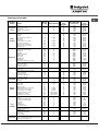
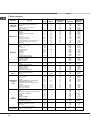
Cooking advice table
Cooking
modes
Foods
Weight
(in kg)
Rack Position
Pre-heating
time
(minutes)
Recommended
temperature
Cooking
time
(minutes)
Traditional
Oven
Duck
Roast veal or beef
Pork roast
Biscuits (short pastry)
Tarts
1
1
1
-
1
3
3
3
3
3
15
15
15
15
15
200
200
200
180
180
65-75
70-75
70-80
15-20
30-35
Multi-
cooking
Pizza (on 2 racks)
Lasagne
Lamb
Roast chicken + potatoes
Mackerel
Plum cake
Cream puffs (on 2 racks)
Biscuits (on 2 racks)
Sponge cake (on 1 rack)
Sponge cake (on 2 racks)
Savoury pies
1
1
1
1+1
1
1
0.5
0.5
0.5
1
1.5
2 and 4
3
2
2 and 4
2
2
2 and 4
2 and 4
2
2 and 4
3
15
10
10
15
10
10
10
10
10
10
15
230
180
180
200
180
170
190
180
170
170
200
15-20
30-35
40-45
60-70
30-35
40-50
20-25
10-15
15-20
20-25
25-30
Soles and cuttlefish
Squid and prawn kebabs
Cuttlefish
Cod filet
Grilled vegetables
Veal steak
Sausages
Hamburgers
Mackerels
Toasted sandwiches (or toast)
0.7
0.6
0.6
0.8
0.4
0.8
0.6
0.6
1
4 and 6
4
4
4
4
3 or 4
4
4
4
4
4
-
-
-
-
-
-
-
-
-
-
100%
100%
100%
100%
100%
100%
100%
100%
100%
100%
10-12
8-10
10-15
10-15
15-20
15-20
15-20
10-12
15-20
3-5
Barbecue
With rotisserie (where present)
Veal on the spit
Chicken on the spit
Lamb on the spit
1.0
1.5
1.0
-
-
-
-
-
-
100%
100%
100%
80-90
70-80
70-80
Grilled chicken
Cuttlefish
1.5
1.5
2
2
10
10
200
200
55-60
30-35
Gratin
With rotisserie (where present)
Veal on the spit
Lamb on the spit
Chicken on the spit +
potatoes (roasted)
1.5
1.5
1.5
-
-
-
-
2
10
10
10
10
200
200
200
200
70-80
70-80
70-75
70-75
Pizza Mode
Pizza
Roast veal or beef
Chicken
0.5
1
1
3
2
2 or 3
15
10
10
220
220
180
15-20
25-30
60-70
Baking
Mode
Tarts
Fruit cakes
Plum cake
Sponge cake
Stuffed pancakes (on 2 racks)
Small cakes (on 2 racks)
Cheese puffs (on 2 racks)
Cream puffs (on 3 racks)
Biscuits (on 3 racks)
Meringues (on 3 racks)
0.5
1
0.7
0.5
1.2
0.6
0.4
0.7
0.7
0.5
3
2 or 3
3
3
2 and 4
2 and 4
2 and 4
1 and 3 and 5
1 and 3 and 5
1 and 3 and 5
15
15
15
15
15
15
15
15
15
15
180
180
180
160
200
190
210
180
180
90
20-30
40-45
40-50
25-30
30-35
20-25
15-20
20-25
20-25
180
Frozen food
Pizza
Courgette and prawn pie
Country style spinach pie
Turnovers
Lasagne
Golden Rolls
Chicken morsels
0.3
0.4
0.5
0.3
0.5
0.4
0.4
2
2
2
2
2
2
2
-
-
-
-
-
-
-
250
200
220
200
200
180
220
12
20
30-35
25
35
25-30
15-20
Pre-cooked food
Golden chicken wings 0.4 2 - 200 20-25
Fast
cooking
Fresh Food
Biscuits (short pastry)
Plum cake
Cheese puffs
0.3
0.6
0.2
2
2
2
-
-
-
200
180
210
15-18
45
10-12
Leavening
Leavening process of dough made with
yeast or baking powder (brioches, bread,
sugar pie, croissants, etc.)

12
GB
Precautions and tips
This appliance has been designed and
manufactured in compliance with international safety
standards. The following warnings are provided for
safety reasons and must be read carefully.
General safety
The appliance was designed for domestic use
inside the home and is not intended for
commercial or industrial use.
The appliance must not be installed outdoors, even
in covered areas. It is extremely dangerous to
leave the appliance exposed to rain and storms.
Do not touch the appliance with bare feet or with
wet or damp hands and feet.
The appliance must be used by adults only for the
preparation of food, in accordance with the
instructions provided in this booklet.
The instruction booklet accompanies a class 1
(insulated) or class 2 - subclass 1 (recessed
between 2 cupboards) appliance.
Do not touch t he heating elements or certain
parts of the oven door when the appliance is in
use; these parts become
extremely hot. Keep
children well away from the appliance.
Make sure that the power supply cables of other
electrical appliances do not come into contact
with the hot parts of the oven.
The openings used for the ventilation and
dispersion of heat must never be covered.
Always use oven gloves when placing cookware
in the oven or when removing it.
Do not use flammable liquids (alcohol, petrol,
etc...) near the appliance while it is in use.
Do not place flammable material in the lower
storage compartment or in the oven itself. If the
appliance is switched on accidentally, the
materials could catch fire.
The internal surfaces of the compartment (where
present) may become hot.
Always make sure the knobs are in the
Position when the appliance is not in use.
When unplugging the appliance, always pull the
plug from the mains socket; do not pull on the cable.
Never perform any cleaning or maintenance work
without having disconnected the appliance from the
electricity mains.
If the appliance breaks down, under no
circumstances should you attempt to perform the
repairs yourself. Repairs carried out by
inexperienced persons may cause injury or further
malfunctioning of the appliance. Contact Assistance.
Do not rest heavy objects on the open oven door.
Do not let children play with the appliance.
The appliance should not be operated by people
(including children) with reduced physical,
sensory or mental capacities, by inexperienced
individuals or by anyone who is not familiar with
the product. These individuals should, at the very
least, be supervised by someone who assumes
responsibility for their safety or receive
preliminary instructions relating to the operation of
the appliance.
If the cooker is placed on a pedestal, take the
necessary precautions to prevent the same from
sliding off the pedestal itself.
Disposal
When disposing of packaging material: observe
local legislation so that the packaging may be
reused.
The European Directive 2002/96/EC relating to
Waste Electrical and Electronic Equipment (WEEE)
states that household appliances should not be
disposed of using the normal solid urban waste
cycle. Exhausted appliances should be collected
separately in order to optimise the cost of re-using
and recycling the materials inside the machine,
while preventing potential damage to the
atmosphere and to public health. The crossed-out
dustbin is marked on all products to remind the
owner of their obligations regarding separated
waste collection. For further information relating to
the correct disposal of exhausted household
appliances, owners may contact the public service
provided or their local dealer.
Respecting and conserving the
environment
You can help to reduce the peak load of the electricity
supply network companies by using the oven in the
hours between late afternoon and the early hours of
the morning. The cooking mode programming
options, the delayed cooking mode (see Cooking
modes) and delayed automatic cleaning mode (see
Care and Maintenance) in particular, enable the user
to organise their time efficiently.
Always keep the oven door closed when using the
BARBECUE and GRATIN modes: This will achieve
improved results while saving energy
(approximately 10%).
Check the door seals regularly and wipe them clean
to ensure they are free of debris so that they adhere
properly to the door, thus avoiding heat dispersion.

GB
13
Switching the appliance off
Disconnect your appliance from the electricity
supply before carrying out any work on it.
Cleaning the appliance
Never use steam cleaners or pressure cleaners on
the appliance.
The stainless steel or enamel-coated external
parts and the rubber seals may be cleaned using
a sponge which has been soaked in lukewarm
water and neutral soap. Use specialised products
for the removal of stubborn stains. After cleaning,
rinse well and dry thoroughly. Do not use abrasive
powders or corrosive substances.
The hob grids, burner caps, flame spreader rings
and burners may be removed to make cleaning
easier; wash them in hot water and non-abrasive
detergent, making sure all burnt-on residue is
removed before drying them thoroughly.
Clean the terminal part of the flame failure safety
devices* frequently.
The inside of the oven should ideally be cleaned
after each use, while it is still lukewarm. Use hot
water and detergent, then rinse well and dry with
a soft cloth. Do not use abrasive products.
Clean the glass part of the oven door using a
sponge and a non-abrasive cleaning product,
then dry thoroughly with a soft cloth. Do not use
rough abrasive material or sharp metal scrapers
as these could scratch the surface and cause the
glass to crack.
The accessories can be washed like everyday
crockery, and are even dishwasher safe.
Do not close the cover when the burners are alight
or when they are still hot.
Inspecting the oven seals
Check the door seals around the oven regularly. If
the seals are damaged, please contact your nearest
Authorised After-sales Service Centre.
We recommend that the oven is not used until the
seals have been replaced.
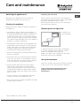
Replacing the oven light bulb
To replace the
oven light bulb:
1. Remove the glass cover using a screwdriver.
2. Unscrew the light bulb and replace it with a
similar one: Wattage 15 W, cap E 14.
Replace the glass cover, making sure the seal is
positioned correctly (see diagram).
Gas tap maintenance
Over time, the taps may become jammed or difficult
to turn. If this occurs, the tap must be replaced.
This procedure must be performed by a
qualified technician authorised by the
manufacturer.
Care and maintenance
*
Only available in certain models.
Glass door
Seal
Lamp
Oven
compartment

14
GB
Automatic cleaning using the FAST
CLEAN function
With the FAST CLEAN mode, the internal
temperature of the oven reaches 500°C. The
pyrolytic cycle is activated, burning away food and
grime residues. Dirt is literally incinerated.
Keep children away from the appliance during the
automatic cleaning cycle as surfaces may become
very hot. Particles may ignite inside the oven due to
the combustion process. There is no cause for
concern: this process is both normal and hazard-
free.
Before initiating the FAST CLEAN mode:
Remove large or coarse food residues from the
inside of the oven using a damp sponge. Do not
use detergents.
Remove all accessories.
Do not place tea towels or pot holders over the
oven handle.
Turn the SELECTOR knob to the 0 position.
! If the oven is too hot, the pyrolytic cycle may not
start. Wait for the oven to cool down.
! The programme may only be started once the oven
door has been closed.
To activate the FAST CLEAN cycle press and hold
the
button for approximately 4 seconds. The
TIMER KNOB may be used to select the desired
cleaning level; there are three default time settings
which cannot be modified.
1. Economy (ECO): turn the knob towards -.
Duration 1 hour.
2. Normal (NOR): initial level. Duration 1 hour and 30
minutes.
3. Intensive (INT): turn the knob towards +.
Duration 2 hours.
4. Press the
button to confirm.
An end time for the FAST CLEAN cycle (as for a
normal cooking cycle) may be programmed (see
Programming the automatic cleaning end time).
Safety devices
The
icon on the display, when lit, indicates
that the oven door was automatically locked as
soon as the temperature reached a high value.
The
icon indicates that the cleaning cycle
may be cancelled at any time by pressing the
button.
If a malfunction occurs, the heating elements will
be switched off.
Once the oven door has been locked, you cannot
change the duration and cycle end time settings.
Programming the automatic cleaning end time
1. Press the
button until the icon and the two
digits on the DISPLAY begin to flash.
2. Turn the TIMER KNOB towards + and - to
adjust the hour value.
3. Press the
button again until the other two
digits on the DISPLAY begin to flash.
4. Turn the TIMER KNOB towards + and - to
adjust the minute value.
5. Press the
button again to confirm.
6. When the set time has elapsed, the text END
appears on the display and a buzzer sounds.
For example: it is 9:00 a.m. and the Economy
(ECO) FAST CLEAN level has been selected, with
the default duration of 1 hour. 12:30 is scheduled
as the end time. The programme will start
automatically at 11:30 a.m.
Programming has been set when the
and
buttons are illuminated. The display shows the FAST
CLEAN end time and duration alternately.
Once the automatic cleaning cycle is over
You will have to wait until the temperature inside the
oven has cooled down sufficiently before you can
open the oven door. You will notice some white dust
deposits on the bottom and the sides of your oven;
remove these deposits with a damp sponge once
the oven has cooled down completely. Alternatively,
you can make use of the already heated oven, in
which case it is not necessary to remove the
deposits, they are completely harmless and will not
affect your food in any way.

GB
15
Assistance
Warning:
The appliance is fitted with an automatic diagnostic system which detects any malfunctions. Malfunctions are
displayed by messages of the following type: F followed by numbers.
Call for technical assistance should a malfunction occur.
Never use the services of an unauthorised technician.
Please have the following information to hand:
The type of problem encountered.
The appliance model (Mod.).
The serial number (S/N).
The latter two pieces of information can be found on the data plate located on the appliance.

16
PL
KUCHENKA I PIEKARNIK
CX65SF9 U/HA
CX65SF9 X U/HA
Spis treci
Instalacja, 17-20
Ustawienie i wypoziomowanie
Pod³¹czenie do sieci elektrycznej
Pod³¹czenie gazu
Dostosowanie do ró¿nych rodzajów gazu
Tabela charakterystyk palników i dysz
Tabela charakterystyk
Opis urz¹dzenia, 21
Widok ogólny
Panel kontrolny
Wywietlacz
Uruchomienie i u¿ytkowanie, 22-26
U¿ytkowanie p³yty grzejnej
Ustawianie zegara
Ustawianie minutnika
U¿ytkowanie piekarnika
Programy pieczenia
Programowanie pieczenia
Porady praktyczne
Tabela pieczenia
Zalecenia i rodki ostro¿noci, 27
Ogólne zasady bezpieczeñstwa
Zalecenia dotycz¹ce odpadów
Oszczêdnoæ i ochrona rodowiska
Konserwacja i utrzymanie, 28-29
Od³¹czenie pr¹du elektrycznego
Czyszczenie urz¹dzenia
Wymiana ¿arówki owietleniowej w piekarniku
Konserwacja kurków gazowych
Czyszczenie automatyczne FAST CLEAN
Serwis Techniczny 30
Instrukcja obs³ugi
Polski, 16
PL
English,1
GB

PL
17
Zachowaæ niniejsz¹ ksi¹¿eczkê instrukcji by móc j¹
konsultowaæ w przysz³oci w dowolnej chwili. W
przypadku sprzeda¿y, odst¹pienia lub przeniesienia
urz¹dzenia, nale¿y upewniæ siê, czy instrukcja
zosta³a przekazana wraz z nim.
Nale¿y uwa¿nie przeczytaæ instrukcjê: zawiera ona
wa¿ne informacje dotycz¹ce instalacji, u¿ytkowania i
bezpieczeñstwa.
Instalacja urz¹dzenia powinna zostaæ wykonana
zgodnie z niniejszymi instrukcjami i przez
wykwalifikowany personel.
Wszelkie dzia³ania w zakresie regulacji lub
konserwacji musz¹ byæ wykonywane przy kuchence
od³¹czonej od zasilania elektrycznego.
Wentylacja pomieszczeñ
Urz¹dzenie mo¿e zostaæ zainstalowane wy³¹cznie w
pomieszczeniach ze sta³¹ wentylacj¹, zgodnie z
obowi¹zuj¹cymi normami krajowymi. W
pomieszczeniu, w którym jest instalowane urz¹dzenie,
musi byæ zapewniony taki dop³yw powietrza, jaki jest
niezbêdny dla prawid³owego spalania gazu (natê¿enie
przep³ywu powietrza nie powinno byæ ni¿sze od 2 m
3
/h
na kW zainstalowanej mocy).
Wloty powietrza, zabezpieczone przez kratki,
powinny mieæ przewód o przekroju u¿ytkowym co
najmniej 100 cm
2
i powinny zostaæ rozmieszczone
tak, aby nie mog³y ulec nawet czêciowemu zatkaniu
(patrz rysunek A).
Wymiar tych wlotów powinien zostaæ zwiêkszony o
100% do minimum 200 cm
2
jeli p³yta robocza
urz¹dzenia nie posiada urz¹dzenia zabezpieczaj¹cego
przed brakiem p³omienia i kiedy dop³yw powietrza
nastêpuje w sposób niebezporedni z przyleg³ych
pomieszczeñ (patrz rysunek B) o ile nie s¹ one
czêciami wspólnymi budynku, pomieszczeniami
zagro¿onymi po¿arem lub sypialniami
wyposa¿onych w przewód wentylacyjny z wyjciem
na zewn¹trz, jak opisano powy¿ej.
Odprowadzanie spalin
Odprowadzanie spalin musi byæ zapewnione przez
okap po³¹czony z kominem o ci¹gu naturalnym i o
sprawnym dzia³aniu lub przez wentylator elektryczny,
który w³¹cza siê automatycznie przy ka¿dym
uruchomieniu urz¹dzenia (patrz rysunki).
Instalacja
Pomieszczenie przyleg³e
Pomieszczenie przeznaczone do przewietrzania
A. B
Po d³u¿szym u¿ytkowaniu urz¹dzenia zaleca siê
otwarcie okna lub zwiêkszenie prêdkoci
ewentualnych wentylatorów.
Skroplone gazy pochodne ropy naftowej, ciê¿sze od
powietrza, opadaj¹ w dó³, dlatego pomieszczenia, w
których znajduj¹ siê butle GPL, powinny byæ
wyposa¿one w otwory wychodz¹ce na zewn¹trz,
umo¿liwiaj¹ce odp³yw do³em ewentualnych wycieków
gazu.
Butle GPL, niezale¿nie od tego czy s¹ puste, czy
czêciowo nape³nione, nie powinny byæ instalowane
ani sk³adowane w pomieszczeniach lub wnêkach
po³o¿onych poni¿ej poziomu pod³ogi (piwnice, itp.).
W pomieszczeniu nale¿y przechowywaæ jedynie
aktualnie u¿ytkowan¹ butlê, z dala od róde³ ciep³a
(piece, kominki, piecyki), mog¹cych doprowadziæ do
wzrostu jej temperatury powy¿ej 50°C.
Ustawienie i wypoziomowanie
Mo¿liwe jest zainstalowanie urz¹dzenia obok mebli,
których wysokoæ nie przekracza poziomu
roboczego.
Nale¿y upewniæ siê, czy ciana stykaj¹ca siê z
ty³em urz¹dzenia wykonana jest z materia³u
niepalnego i odpornego na ciep³o (T 90°C).
Dla zapewnienia prawid³owej instalacji:
ustawiæ urz¹dzenie w kuchni, w jadalni lub w
innym pomieszczeniu (nie w ³azience);
jeli p³aszczyzna kuchenki jest wy¿sza w
stosunku do p³aszczyzny mebli, powinny one
zostaæ umieszczone w odleg³oci co najmniej 600
mm od urz¹dzenia;
jeli kuchenka jest instalowana pod szafk¹ wisz¹c¹,
powinna ona znajdowaæ siê w odleg³oci minimum
420 mm od p³yty kuchenki.
A
Otwarcie wentylacji dla
powietrza do spalania
Zwiêkszenie szczeliny
pomiêdzy drzwiami a pod³og¹
Odprowadzanie
bezporednio na
zewn¹trz
Odprowadzanie przez komin lub
rozga³êziony kana³ dymowy
(wy³¹cznie do urz¹dzeñ
kuchennych)

18
PL
Odleg³oæ ta powinna
wynosiæ 700 mm, jeli
szafki wisz¹ce s¹
³atwopalne (patrz
rysunek);
nie umieszczaæ
zas³on za kuchenk¹,
ani w odleg³oci
mniejszej ni¿ 200 mm
od jej krawêdzi;
ewentualne okapy
powinny zostaæ
zainstalowane wed³ug zaleceñ odpowiedniej
instrukcji.
Wypoziomowanie
Jeli konieczne jest
wypoziomowanie urz¹dzenia,
nale¿y przykrêciæ nó¿ki
regulacyjne, dostarczane jako
wyposa¿enie, w odpowiednich
gniazdach umieszczonych w
rogach podstawy kuchenki
(patrz rysunek).
Nó¿ki* mocowane s¹ w
otworach pod podstaw¹
kuchenki.
Pod³¹czenie do sieci elektrycznej
Zamocowaæ na przewodzie znormalizowan¹ wtyczkê
dostosowan¹ do obci¹¿eñ wskazanych na tabliczce
znamionowej umieszczonej na urz¹dzeniu (patrz
tabela Dane techniczne).
W przypadku bezporedniego pod³¹czenia do sieci
koniecznym jest zainstalowanie pomiêdzy
urz¹dzeniem a sieci¹ wy³¹cznika polowego z
otwarciem minimalnym pomiêdzy stykami 3 mm
przeznaczonego do obci¹¿eñ i odpowiadaj¹cego
obowi¹zuj¹cym normom (przewód uziemienia nie
powinien byæ przerywany przez wy³¹cznik). Przewód
zasilania powinien byæ umieszczony tak, aby w
¿adnym punkcie jego temperatura nie przekracza³a
temperatury otoczenia o 50°C.
Przed wykonaniem pod³¹czenia nale¿y upewniæ siê, czy:
gniazdko posiada odpowiednie uziemienie i jest
zgodne z obowi¹zuj¹cymi przepisami;
gniazdko jest w stanie wytrzymaæ maksymalne
obci¹¿enie mocy urz¹dzenia, wskazane na
tabliczce znamionowej;
napiêcie zasilania odpowiada wartociom podanym
na tabliczce znamionowej;
HOOD
420
Min.
min. 650 mm. with hood
min.
700 mm. without hood
mm.
600
Min. mm.
420
Min. mm.
gniazdko jest kompatybilne z wtyczk¹ urz¹dzenia.
Jeli gniazdko nie jest kompatybilne, wymieniæ
gniazdko lub wtyczkê; nie stosowaæ przed³u¿aczy
ani rozga³êników.
Po zainstalowaniu urz¹dzenia przewód elektryczny
i gniazdko pr¹du powinny byæ ³atwo dostêpne.
Kabel nie powinien mieæ zgiêæ, ani nie powinien
byæ zgnieciony.
Przewód musi byæ okresowo sprawdzany i
wymieniany wy³¹cznie przez autoryzowany personel
techniczny.
W przypadku nie przestrzegania powy¿szych
warunków producent zwolniony zostanie z
wszelkiej odpowiedzialnoci.
Pod³¹czenie gazu
Pod³¹czenie do sieci gazowej lub do butli gazowej
mo¿e byæ wykonane przy pomocy przewodu
giêtkiego gumowego lub stalowego, zgodnie z
obowi¹zuj¹cymi normami krajowymi oraz po
upewnieniu siê czy urz¹dzenie jest wyregulowane
odpowiednio dla typu gazu, którym bêdzie zasilane
(patrz etykieta kalibracyjna na pokrywie: w
przeciwnym razie patrz ni¿ej). W przypadku
zasilania p³ynnym gazem z butli, stosowaæ
regulatory cinienia zgodne z obowi¹zuj¹cymi
normami krajowymi. Dla u³atwienia pod³¹czenia
zasilanie gazem mo¿e byæ skierowane bocznie*:
zast¹piæ z³¹czkê przewodu giêtkiego zatyczk¹ i
wymieniæ uszczelkê, dostarczan¹ jako wyposa¿enie.
Dla zapewnienia bezpieczeñstwa pracy,
odpowiedniego zu¿ycia energii i zwiêkszenia trwa³oci
urz¹dzenia, nale¿y siê upewniæ czy cinienie
zasilania mieci siê w granicach wskazanych w tabeli
Charakterystyka palników i dysz (patrz ni¿ej).
Pod³¹czenie gazu przy pomocy przewodu
gumowego
Sprawdziæ czy przewód odpowiada obowi¹zuj¹cym
normom krajowym. Wewnêtrzna rednica przewodu
powinna wynosiæ: 8 mm przy zasilaniu gazem
p³ynnym; 13 mm przy zasilaniu metanem.
Po wykonaniu pod³¹czenia upewniæ siê czy przewód:
nie styka siê w ¿adnym punkcie z czêciami,
które osi¹gaj¹ temperatury przekraczaj¹ce 50°C;
nie jest nara¿ony na naci¹gniêcie ani poskrêcanie
i nie ma na nim zagiêæ lub przewê¿eñ;
nie ma stycznoci z przedmiotami tn¹cymi,
ostrymi krawêdziami, ruchomymi czêciami i nie
jest przygnieciony;
jest ³atwo dostêpny na ca³ej d³ugoci dla
umo¿liwienia wykonywania kontroli jego stanu;

PL
19
jego d³ugoæ wynosi mniej ni¿ 1500 mm;
jest dobrze umocowany na dwóch koñcach za
pomoc¹ odpowiednich zacisków mocuj¹cych,
zgodnych z obowi¹zuj¹cymi normami krajowymi.
Jeli nie mo¿e byæ spe³niony jeden z tych
warunków lub ich wiêksza liczba, albo jeli kuchenka
jest instalowana zgodnie z warunkami klasy 2 -
podklasy 1 (urz¹dzenie umiejscowione pomiêdzy
dwoma meblami), nale¿y zastosowaæ przewód giêtki
stalowy (patrz ni¿ej).
Pod³¹czenie gazu przy pomocy przewodu
giêtkiego ze stali n ierdzewnej o pe³nych
ciankach z gwintowanymi z³¹czami.
Sprawdziæ czy przewód i uszczelki odpowiadaj¹
obowi¹zuj¹cym normom krajowym.
Aby zamontowaæ przewód nale¿y usun¹æ z³¹czkê
przewodu giêtkiego znajduj¹c¹ siê na urz¹dzeniu
(z³¹cze wejciowe gazu do urz¹dzenia jest
gwintowane gwintem gazowym 1/2 walcowym
mêskim).
Wykonaæ pod³¹czenie tak, aby ca³kowita d³ugoæ
przewodów nie przekracza³a 2 metrów oraz upewniæ
siê czy przewód nie styka siê z ruchomymi
czêciami i czy nie jest przygnieciony.
Kontrola szczelnoci
Po zakoñczeniu instalacji sprawdziæ szczelnoæ
wszystkich z³¹cz stosuj¹c w tym celu roztwór
mydlany, nigdy p³omieñ.
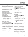
Dostosowanie do ró¿nych rodzajów gazu
Urz¹dzenie mo¿e byæ dostosowane do innego
rodzaju gazu ni¿ ten, którym jest aktualnie zasilane
(wskazany na etykiecie kalibracyjnej na pokrywie).
Dostosowanie p³yty grzejnej
Wymiana dysz palników p³yty:
1. zdj¹æ kratki i wykrêciæ palniki z gniazd;
2. odkrêciæ dysze, pos³uguj¹c
siê kluczem rurowym 7 mm
(patrz rysunek) i wymieniæ je
na te, które s¹ przystosowane
do nowego rodzaju gazu (patrz
tabela Charakterystyka
palników i dysz);
3. przywróciæ na swoje
miejsce wszystkie
komponenty wykonuj¹c
czynnoci w kolejnoci
odwrotnej w stosunku do
powy¿szej sekwencji.
Regulacja minimum palników p³yty:
1. ustawiæ kurek w po³o¿eniu minimum;
2. zdj¹æ pokrêt³o i krêciæ rub¹ regulacyjn¹
znajduj¹c¹ siê wewn¹trz lub obok osi kurka a¿ do
uzyskania ma³ego regularnego p³omienia.
W przypadku gazów p³ynnych ruba regulacyjna
powinna byæ dokrêcona do koñca;
3. sprawdziæ czy podczas szybkiego obracania
pokrêt³em z po³o¿enia maksymalnego do
minimalnego nie nastêpuje ganiêcie palników.
Palniki p³yty nie wymagaj¹ regulacji powietrza
pierwotnego.
Po wykonaniu regulacji dla gazu innego ni¿
oryginalnie przewidziany, nale¿y wymieniæ
poprzedni¹ etykietê kalibracyjn¹ na etykietê
odpowiadaj¹c¹ nowemu gazowi, dostêpn¹ w naszych
Autoryzowanych Centrach Obs³ugi Technicznej.
W sytuacji, gdy cinienie gazu jest inne (lub
zmienne) od przewidzianego, konieczne jest
zainstalowanie na przewodach doprowadzaj¹cych
regulatora cinienia, zgodnie z obowi¹zuj¹c¹ norm¹
krajow¹ dotycz¹c¹ kana³owych regulatorów gazu.

20
PL
Tabela charakterystyk palników i dysz
CX65SF9 U/HA
CX65SF9 X U/HA
Tabela 1 (dla Polski)
G20 (GZ50)
GZ350 (GZ35)
G30 (GPB)
Palnik
rednica
(w mm)
Moc cieplna
(p.c.i.*)
kW
Dysza
1/100
(w mm)
Przep³yw*
l/godz
Dysza
1/100
(w mm)
Przep³yw*
l/godz
Moc cieplna
(p.c.i.*)
kW
Dysza
1/100
(w mm)
Przep³yw*
g/godz
Du¿y (R) 100 2.70 116 285 183 398 2,70 86 225
Pó³szybki (redni) (S) 75 1,70 106 180 143 251 1,70 70 142
Pomocniczy (ma³y) (A) 55 0,90 79 95 106 133 0,90 50 75
Potrójna korona (TC) 130 3,00 133 317 197 442 3,00 91 250
Cinienia zasilania
minimalne (mbar)
nominalne (mbar)
maksymalne (mbar)
16
20
25
10
13
16
29
36
44
* A 0°C e 1013 mbar – gaz suchy
G20 (GZ50) p.c.i. = 35.9 MJ/m³
GZ350 (GZ35) p.c.i. = 25.8 MJ/m³
G30
(
GPB
)
p
.c.i. = 123.6 MJ/m³
TC
A
S
R
DANE TECHNICZNE
Wymiary
piekarnika W x D
x G
39x41x34 cm
Objêtoæ
(l) 56
Wymiary
u¿ytkowe
szuflady do
podgrzewania
potraw
szerokoæ (cm) 42
g³êbokoæ (cm) 44
wysokoæ (cm) 8,5
Palniki
mog¹ byæ dostosowane do
wszystkich rodzajów gazu
wskazanych na tabliczce
znamionowej
Napiêcie i
czêstotliwoæ
zasilania
elektrycznego
patrz tabliczka znamionowa
ENERGY LABEL
Dyrektywa 2002/40/WE na
etykiecie piekarników elektrycznych
Norma EN 50304 Zu¿ycie energii
konwekcja naturalna — funkcja
ogrzewania: Tradycyjne;
Zu¿ycie energii deklaracja Klasa
konwekcji wymuszona — funkcja
ogrzewania:
Zapiekanki
Dyrektywy unijne: 2006/95/CEE z
dnia 12/12/06 (niskie napiêcie) z
póniejszymi zmianami -
89/336/CEE z dnia 3/05/89
(zgodnoæ elektromagnetyczna) z
póniejszymi zmianami -
93/68/CEE z dnia 22/07/93 z
póniejszymi zmianami,
90/369/CEE z dnia 29/06/90 (gaz)
z póniejszymi zmianami, -
93/68/CEE z dnia 22/07/93 z
póniejszymi zmianami, -
2002/96/EC.
Strona jest ładowana ...
Strona jest ładowana ...
Strona jest ładowana ...
Strona jest ładowana ...
Strona jest ładowana ...
Strona jest ładowana ...
Strona jest ładowana ...
Strona jest ładowana ...
Strona jest ładowana ...
Strona jest ładowana ...
Strona jest ładowana ...
Strona jest ładowana ...
-
 1
1
-
 2
2
-
 3
3
-
 4
4
-
 5
5
-
 6
6
-
 7
7
-
 8
8
-
 9
9
-
 10
10
-
 11
11
-
 12
12
-
 13
13
-
 14
14
-
 15
15
-
 16
16
-
 17
17
-
 18
18
-
 19
19
-
 20
20
-
 21
21
-
 22
22
-
 23
23
-
 24
24
-
 25
25
-
 26
26
-
 27
27
-
 28
28
-
 29
29
-
 30
30
-
 31
31
-
 32
32


Indesit CX65SF9 X U /HA instrukcja
- Kategoria
- Piekarniki
- Typ
- instrukcja
w innych językach
- English: Indesit CX65SF9 X U /HA User guide
Powiązane dokumenty
-
Indesit CX65SF9 X U instrukcja
-
Hotpoint FHS G IX/HA instrukcja
-
-
-
-
-
-
-
-
Inne dokumenty
-
Whirlpool K6G52.A (W)/U instrukcja
-
Whirlpool CP 6V F8 EE instrukcja
-
-
-
-
-
Whirlpool C 349 PV.2 (X)U instrukcja
-
-
-
Freggia OMRB66CH Instrukcja obsługi