
NVENT RAYCHEM EM2-CM-MAT
Electrical heating mat for ramp snow melting and track heating
SYSTEM EM2-CM-MAT
Freiflächenheizmatte für schnee- und eisfreie Garagenzufahrten,
Rampen und Gehwege
TRAME EM2-CM
Trame chauffante pour déneigement de rampes d’accès
SYSTEM EM2-CM-MAT
Elektryczna mata grzewcza do ochrony przed oblodzeniem i zaleganiem śniegu
na rampach i podjazdach
EM2-CM-MAT
Электрические греющие маты для стаивания снега на подъездных
площадках и подогрева дорожного полотна
EM2-CM-MAT
Elektrische verwarmingsmat voor toegangen en opritten
EM2-CM VÄRMEMATTA
Elektrisk värmematta för snösmältning och uppvärmning av ramper och hjulspår
EM2-CM-MATTE
Elektrisk varmematte for snøsmelting på ned/oppkjørsel og sporvarming
EM2-CM SULANAPITOMATTO
Sulanapitomatto ulkoalueiden sulanapitoon
EM2-CM-Mat

2 | nVent.com
EM2-CM-Mat
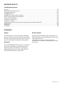
Installation Manual ............................................................................................................................... 6
System EM2-CM-Mat
Installations- und Betriebshandbuch ................................................................................................... 19
Trame EM2-CM
Instructions d’installation ..................................................................................................................... 32
System EM2-CM-Mat
Instrukcja montażu i obsługi ................................................................................................................. 45
EM2-CM-Mat
Руководство по установке и эксплуатации ................................................................................... 59
EM2-CM-Mat
Installatiehandleiding ............................................................................................................................ 73
EM2-CM värmematta
Installationshandbok ............................................................................................................................ 86
EM2-CM-matte
Installasjonsmanual .............................................................................................................................. 99
EM2-CM sulanapitomatto
Asennusohje .......................................................................................................................................... 112

nVent.com | 3
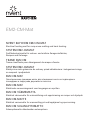
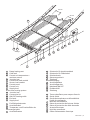
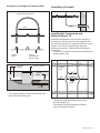
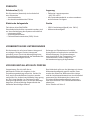
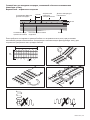
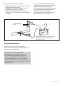
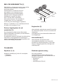
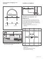
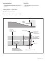
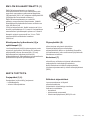
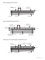
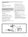
1
Ramp heating mat
2
Cold lead
3
Control unit temperature +
moisture sensor
4
Junction box
5
Connection lead conduit
6
Sensor lead conduit
7
Control panel
8
Control unit
9
Supply lead
Drain trace heating system
10
Junction box
11
Connection kit
12
GM-2XT heating cable
13
End seal
14
Supply lead
1
Freiflächenheizmatte
2
Anschlußkabel
3
Temperatur- und Feuchtefühler der
Steuerungseinheit
4
Anschlußkasten
5
Schutzrohr für Anschlusskabel
6
Schutzrohr für Fühlerkabel
7
Schaltschrank
8
Steuerungseinheit
9
Zuleitung
Rinnenbeheizung
10
Anschlußkasten
11
Anschlußgarnitur
12
Heizband GM-2XT
13
Endabschluß
14
Zuleitung
1
Trame chauffante pour rampes d’accès
2
Sortie froide
3
Sonde de température et d’humidité de
l’unité de commande
4
Boîte de raccordement
5
Gaine de protection de liaisons froides
6
Gaine de protection du câble de sonde
7
Armoire électrique
8
Unité de commande
9
Câble d’alimentation électrique
1.5
4
2
3
2
1
12
13
7
8
6
5
9
14
10
11
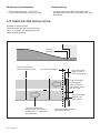
5
Garage
60 cm
60 cm

4 | nVent.com
Système de traçage de drain
10
Boîte de raccordement
11
Kit de connexion
12
Ruban chauffant GM-2XT
13
Terminaison
14
Câble d’alimentation électrique
1
Mata grzewcza do ogrzewania podjazdów
2
Przewód zasilający
3
Czujnik temperatury i wilgotności gruntu
4
Skrzynka przyłączeniowa
5
Rurka ochronna przewodu zasilającego
6
Rurka ochronna przewodu czujnika
7
Rozdzielnica sterująca
8
Sterownik
9
Przewód zasilający
System ogrzewania odwodnienia liniowego
10
Skrzynka przyłączeniowa
11
Zestaw przyłączeniowy
12
Przewód grzejny GM-2XT
13
Zestaw zakończeniowy
14
Przewód zasilający
1
Греющий мат
2
Холодный ввод
3
датчик температуры и влажности
4
Соединительная коробка
5
Кабелепровод для соединительного
кабеля
6
Кабелепровод для датчика
7
Панель управления
8
Устройство управления
9
Подвод питания
Система обогрева дренажа
10
Соединительная коробка
11
Набор для соединения
12
Греющий кабель GM-2XT
13
Концевая заделка
14
Подвод питания
1
Verwarmingsmat
2
Aansluitkabel
3
Vocht- en temperatuursensor
4
Aansluitdoos
5
Elektriciteitsbuis
6
Buis voor sensorkabel
7
Schakelkast
8
Besturing
9
Voedingskabel
10
Aansluitdoos
11
Verbindingskit
12
GM-2XT verwarmingskabel
13
Eindafsluiting
14
Voedingskabel
1
Rampvärmematta
2
Kalledare
3
Temperaturregulator och fukthaltsgivare
4
Kopplingsbox
5
Rör för anslutningskabel
6
Rör för givarledning
7
Automatikskåp
8
Reglerenhet
9
Matarkabel
Värmekabelsystem för dräneringsränna
10
Kopplingsbox
11
Anslutningssats
12
Värmekabel GM-2XT
13
Ändavslutning
14
Matarkabel
1
Varmematte for ned/oppkjørsel
2
Kaldleder
3
Betjeningspaneltemperatur + fuktighetsføler
4
Koplingsboks
5
Ledningsrør for tilslutningsledning
6
Ledningsrør for følerleder
7
Kontrollpanel
8
Kontrollenhet
9
Tilførselsleder
Varmesystem for drenering
10
Koplingsboks
11
Tilkoplingsutstyr
12
GM-2XT-varmekabel
13
Endeforsegling
14
Tilførselsleder
1
Ajoluiskan lämpömatto
2
Kylmäkaapeli
3
Ohjausyksikön lämpötila-
ja kosteusanturi
4
Kytkentärasia
5
Liitäntäjohtimen suojaputki
6
Anturijohtimen suojaputki
7
Ohjauskeskus
8
Säätöyksikkö
9
Syöttökaapeli
Viemärin lämmitysjärjestelmä
10
Kytkentärasia
11
Kytkentäpakkaus
12
Lämpökaapeli GM-2XT
13
Loppupääte
14
Syöttökaapeli

nVent.com | 5
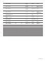
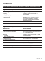
EN
Type - Mat length
(230 Vac - 300 W/m
2
)
Dimensions Area Conductor
Resistance
(+/–10%)
Power output
(230 Vac)
Electrical protection
(C Type)
DE
Typ - Heizmatte
(230 Vac - 300 W/m
2
)
Abmessungen Fläche Leitungs-
Widerstand
(+/–10%)
Leistung (230
Vac)
Ausgang
Elektrische Absicherung
(C Typ)
FR
Type – Longueur de trame
(230 V ca - 300 W/m
2
)
Dimensions Surface Résistance du
conducteur
(+/–10%)
Puissance de
sortie (230 V ca)
Protection électrique
(Type C)
PL
Typ maty grzewczej - długość
(230 Vac - 300 W/m
2
)
Wymiary Pow. maty Rezystancja w omach
(+/–10%)
Moc
(230 V AC )
Zabezpieczenie
elektryczne
(Charakterystyka C)
RUS
Tип - Греющий мат
для стаивания снега длиной
(230 Vac - 300 W/m
2
)
Размеры Площадь Сопротивление
(+/–10%)
Мощн
ость
(230 Vac)
Электрическая защита
(C Tип)
NL
Type - Verwarmingsmat
lengte
(230 Vac - 300 W/m
2
)
Afmetingen Oppervlak
Geleiderweerstand
(+/–10%)
Vermogen
(230 Vac)
Elektrische zekering
(Type C)
SW
Typ – mattlängd
(230 VAC, 300 W/m
2
)
Mått Yta Total resistans
(+/–10 %)
Uteffekt
(vid 230 VAC)
Säkringsstorlek
(typ C)
N
Type - Mattelengde
(230 Vac - 300 W/m
2
)
Størrelse Område Ledermotstand
(+/–10 %)
Strømeffekt
(230 Vac)
Elektrisk beskyttelse
(C-type)
FI
Tyyppi – matto pituus
(230 V AC – 300 W/m
2
)
Mitat Alue Johtimen resistanssi
(+/–10 %)
Antoteho
(230 V AC)
Sähkösuojaus
(tyyppi C)
m x m m
2
Ohm W A
EM2-CM-Mat-2m
2 x 0,6 1,2 130,3 400 10 A
EM2-CM-Mat-3m
3 x 0,6 1,8 102,5 520 10 A
EM2-CM-Mat-4m
4 x 0,6 2,4 79,9 670 10 A
EM2-CM-Mat-5m
5 x 0,6 3 57,1 930 10 A
EM2-CM-Mat-7m
7 x 0,6 4,2 47,5 1140 10 A
EM2-CM-Mat-10m
10 x 0,6 6 28,9 1860 10 A
EM2-CM-Mat-13m
13 x 0,6 7,8 22,1 2560 16 A
EM2-CM-Mat-16m
16 x 0,6 9,6 18,5 2890 16 A
EM2-CM-Mat-21m
21 x 0,6 12,6 13,8 3730 20 A

6 | nVent.com
EM2-CM-MAT
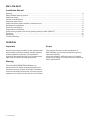
Installation Manual
General .......................................................................................................................................................... 6
EM2-CM-Mat heating system ...................................................................................................................... 7
Additional items ........................................................................................................................................... 7
Layout considerations ................................................................................................................................. 8
Preparing subsurface .................................................................................................................................. 9
Cable resistance and insulation resistance test ........................................................................................ 9
Heating mat installation ............................................................................................................................ 10
Check the installation ................................................................................................................................ 14
Top surface installation ............................................................................................................................. 14
Drain tracing system with self-regulating heating cable (GM-2XT) ........................................................ 15
Finishing ..................................................................................................................................................... 16
Operating .................................................................................................................................................... 16
Trouble shooting ........................................................................................................................................ 17
GENERAL
Important
All the instructions provided in this manual must
be followed carefully to ensure that the heating
system operates correctly. The installation
must also be compliant with local requirements
applicable to electrical heating systems.
Warning
The nVent RAYCHEM EM2-CM-Mat is an
electrical device which must be designed and
installed correctly. Follow all design, installation,
test and operating instructions to ensure proper
operation and to prevent electrical or fire hazard.
Scope
This manual focuses on the installation of
EM2-CM-Mat in screed and sand for long-term
structural stability.
nVent can supply a different series of suitable
products for laying in screed/concrete, asphalt or
other applications.

nVent.com | 7
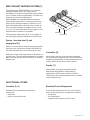
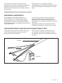
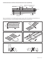
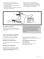
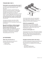
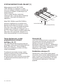
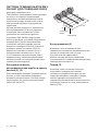
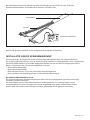
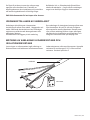
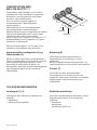
EM2-CM-MAT HEATING SYSTEM (1)
The heating mat “EM2-CM-Mat” is a constant
wattage heating device for a permanent
installation in screed or sand under paving slabs.
It is a 230Vac system regulated by a control unit.
(Control unit provided separately.)
EM2-CM-Mat is a preterminated and ready to
install heating mat with 1 cold lead connection
and a power output of approx. 300 W/m² or 25
W/m of heating cable. All mats have a width of
0.6 m and are available in lengths from 2 m up
to 21 m. The cold lead cable has a length of 4 m,
and should be installed in a conduit.
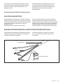
The minimum cable spacing is 10 cm. With 10
cm spacing the power output will be 300 W/m².
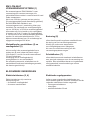
Spacer, Junction box (4) and
supply lead (9)
When it is necessary to loosen the heating cable
from the mat, the plastics strips (VIA-Strips-PL)
will help maintain the correct spacing (10 cm).
Extension of the cold leads needs to be done in a
junction box. The connection between the control
panel and the junction box is made by a suitable
supply lead.
Controller (8)
nVent offers control units specially designed
for ramp heating applications. They incorporate
combined temperature and moisture sensors to
ensure efficient operation of the system.
Panels (7)
nVent offers a range of standard panels
specifically designed for ramp heating
applications. Each panel contains a built in
control unit, plus circuit breakers and a residual
current device (rcd).
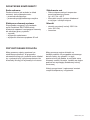
ADDITIONAL ITEMS
Conduits (5, 6)
Conduits (not included) are required to
protect the
• cold lead
• sensor connection lead.
Electrical Control Equipment
If nVent standard panels are not used, further
items will be required to complete the system:
• contactors
• circuit breakers
• residual current device (rcd) 30 mA.
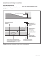
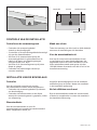
60 cm
10 cm
cold lead
connection

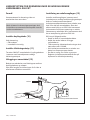
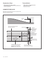
8 | nVent.com
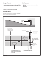
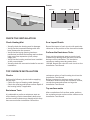
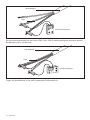
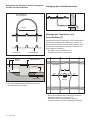
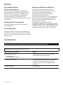
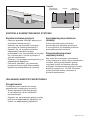
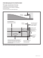
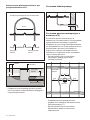
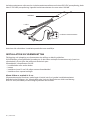
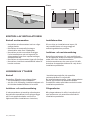
Covered
area
Lay the heating cable right
up to the drain-off gutter.
Covered area
Also heat the surfaces on
which braking will occur, e.g.
before a barrier or a magnetic
card reader.
Also heat
the drain-off
gutter.
Also heat the
covered area of the
entry, as incoming
vehicles can bring in
snow.
Do not run the
heating mat over
expansion joints.
Storage of the mat
• Storage temperature range: –40°C to +45°C
• Store all system elements in a clean, dry place.
Test Equipment
• 2500 Vdc insulation resistance tester (min.
500 Vdc)
• Ohmmeter
LAYOUT CONSIDERATIONS
Area to be heated
Determine the exact area to be heated, e.g. wheel
tracks. Consider the following factors:
Heat at least one
metre into the
covered area.

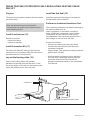
nVent.com | 9
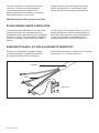
Cold lead
Conductor
Ohmmeter
First make sure that the area to be heated
complies with the data in the design instructions.
Establish where the junction boxes are to be
installed and check that the connection leads are
long enough.
The length is 4 m. Thoroughly clean the
substratum before starting to install the heating
mat, as sharp objects can damage the heating
cable.
The EM2-CM-Mat must not be shortened or spliced.
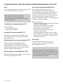
PREPARING SUBSURFACE
The heating mat should be installed on a
stable subsurface. In suspended structures
the substratum may consist of finished slabs,
prestressed concrete or a suspended structure
with poured concrete.The heating mat can be laid
on all subsurfaces.
In the case of poured concrete, it should be
ensured that the surface is smooth and all
sharp objects are removed. Ramps on a solid
substratum do not require any additional thermal
insulation.
Appropriate preparations should be made for
installing the temperature and moisture sensor.
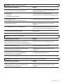
CABLE RESISTANCE AND INSULATION RESISTANCE TEST
Testing the heating mat involves the measuring
of the conductor resistance and the cable
electrical insulation resistance.
The conductor resistance is measured with
an ohmmeter. A deviation of up to 10% from
the nominal resistance is permissible. See table
on page 5.

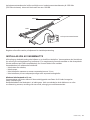
10 | nVent.com
The insulation resistance should be measured with the aid of a 2500 Vdc
(500 Vdc minimum) insulation resistance tester. The reading should be 100Mohms min.
Record all the measured values on the Installation Test Record provided.
Cold lead
Conductor
Insulation
resistance
tester
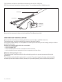
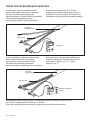
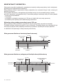
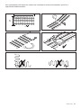
HEATING MAT INSTALLATION
All connections and electrical testing should be carried out by a qualified electrician.
The heating mats should be installed for ramp and driveway heating.
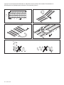
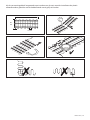
For irregular shaped areas, it is acceptable to cut the tape of the mat (not the heating cable) in order to
cover the entire area.
However, the heating cable within the mat should:
• not be cut or damaged,
• not be crossed over
• not be installed within 10 cm of another section of heater,
• not be installed across expansion joints or separate concrete slabs.
Minimum cable spacing is 10 cm
The heating mats must be secured to the underlaying surface to prevent movement during the
installation.
The cold lead cable should be protected in a conduit. The entire length of heating cable should be
covered by wet sand-cement mixture, screed, or dry sand depending on the selected top surface.

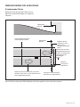
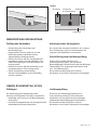
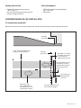
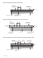
nVent.com | 11
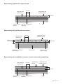
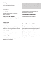
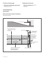
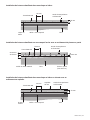
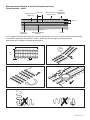
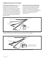
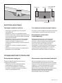
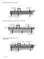
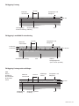
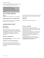
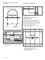
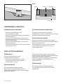
Ramp heating embedded in cement screed
Cement screed
ground
50 mm
100 mm
SoilConcrete / compacted
substrate
EM2-CM ramp
heating mat
Temperature and
moisture sensor
Ramp heating with top oor stones or pavers
Sand bed / or cement /
sand mixture
20-30 mm
100 mm
Stones / paver
(max. 80 mm)
Soil ground
EM2-CM ramp
heating mat
60-80 mm
30-50 mm
Temperature and
moisture sensor
Ramp heating mat embedded in concrete / cement screed under asphalt layer
Cement screed
ground
50 mm
100 mm
SoilConcrete / compacted
substrate
EM2-CM ramp
heating mat
Asphalt layer
25 mm
Temperature and
moisture sensor

12 | nVent.com
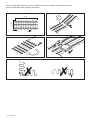
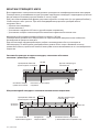
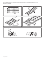
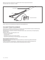
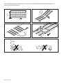
If the heating cable has to be loosened from the mat, the installer should use the plastic
spacer to keep the cable spacing consistent.
60
cm
xx m
10 cm

nVent.com | 13
Use Spacers to arrange loose heating cable
Laying spacing as given
Spacer
(prestamped
plastic strip)
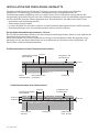
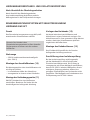
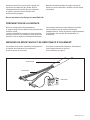
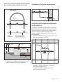
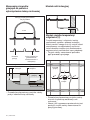
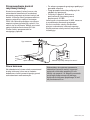
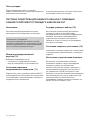
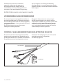
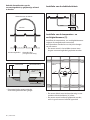
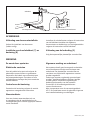
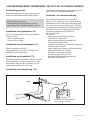
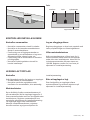
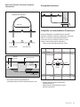
Installation of Conduit
Installing the Temperature and
Moisture Sensor (3)
Install the temperature and moisture sensor in
accordance with the instructions supplied with
the unit. Ensure that it is supported at the correct
height. For sensors comprising a separate
housing and sensor, install only the housing at
this stage.
• The sensor should be placed mid-way between
heating cable runs.
Heating
cable
10 cm
• The sensor lead should be routed under the
layer with the heating mat.
• The sensor lead should be protected by
a metal conduit (6).
• The sensor must be mounted vertically,
even on inclined surfaces.
==
50505050
Sensor
Heating
cable
Sensor housing
Heating
cable
Conduit
Concrete/
Screed

14 | nVent.com
Surface Sensor Filling material
Sub surface
Sensor
CHECK THE INSTALLATION
Check Heating Mat
• Visually check the heating mat for damage.
• Verify that the loosened heating cable has
been fastened to the spacers.
• Verify that the laying spacing has been
maintained and that the heating mat has been
kept away from expansion joints, sharp
edges, etc.
• Verify that the heating mat has been installed
at the correct depth.
• Visually check the connection leads for correct
installation.
Do a Layout Sketch
Record the layout of each circuit, with particular
reference to the position of the connection leads.
Perform the Resistance Tests
Carry out the resistance tests on each circuit
to detect any damage that may have occurred
during or after installation. The insulation
resistance reading must be greater than
100 MΩ. Record the value for each circuit on the
Installation Test Record.
TOP SURFACE INSTALLATION
Checks
Perform the following checks before applying
the top layer:
• Check for signs of heating cable damage.
• Check the spacing and below-surface depth of
the heating cable, if applicable.
Resistance Tests
It is advisable to perform resistance tests on
all the heating circuits immediately before top
surface works to detect any damage which may
have occurred after installation. Record the
resistance values of each heating circuit on the
Installation Test Record.
Before commencing top layer works, ask the
installation team to verify the resistance results,
record the measured values and sign the
Installation Test Record.
Top surface works
After completion of all surface works, perform
the resistance tests and record the values on the
Installation Test Record.

nVent.com | 15
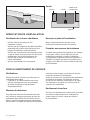
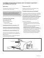
DRAIN TRACING SYSTEM WITH SELF-REGULATING HEATING CABLE
GM-2XT
Purpose
The drain tracing system ensures that melt water
can drain away.
Note: the drain tracing circuit should be
controlled by the same control system as the
other heating circuits.
Install Junction box (10)
Choose a position:
• close to the drain
• indoors if possible.
Install Connection Kit (11)
Terminate the GM-2XT heating cable into the
junction box in accordance with the instructions
provided with the Connection Kit.
Lay out the Heating cable (12)
Protect the heating cable with conduit
between the junction box and the drain. Trace
the entire length of the drain to ensure that melt
water will always have a drain-off path.
Install the End Seal (13)
Install the end seal following the instructions
provided with the End Seal kit.
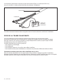
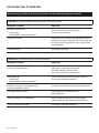
Perform an Insulation Resistance Test
The insulation resistance test detects damage to
the heating cable such as
cuts or punctures. It should be carried out
using a 2500 Vdc instrument. Lower voltage
instruments are less sensitive and are not
recommended. The instrument should have a
test voltage of not less than 500 Vdc.
Proceed as follows:
• Connect one lead to the heat strip braid.
• Connect the other lead to both heat strip
conductors together.
• Apply voltage. The resistance reading must be
greater than 100 MΩ.
• If the insulation resistance is less than this,
the heat strip is damaged. Where possible,
locate the fault and rectify. Record the
insulation resistance value on the Installation
Test Record.
Braid
2500 Vdc Insulation resistance tester
Conductors

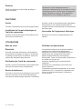
16 | nVent.com
Finishing
Install a grid over the drain to ensure that the heat
strip is protected from damage.
Note: A 30 mA residual current device (rcd)
is required for the drain tracing. Ensure that
there are no more than 60 m of heating cable
connected to each 16A fuse.
FINISHING
Complete Sensor
Complete the installation of the sensor
(where necessary).
Install Panel and Controls
Install the electrical panels according to the
manufacturer’s instructions. Install control units,
thermostats and manual
control equipment in accordance with the
manufacturers’ instructions.
Complete Wiring and System
Follow applicable local regulations.
OPERATION
Initial Start-up
Electrical Requirements
Complete all electrical testing following
applicable local codes and practices. Inspect
all wiring for conformance to design drawings.
Check for correct rating on all protection devices.
Controller Checks
Check controller in accordance with the
instructions provided with the unit.
Resistance Tests
Perform final resistance test to ensure that the
connection lead and supply cable have not been
damaged since installation.
General Operation and Maintenance
The system has no moving parts and
therefore requires minimum maintenance.
Local maintenance codes and requirements for
electrical equipment should be complied with.
Circuit breakers should be checked periodically.
Residual current devices (rcd) should be tested
at least annually.
Periodically inspect the system controls.
Operate the controls to ensure that they
function correctly.
Max. exposure temperature for heating mat:
65°C. Installer must supply operator/owner with
the layout drawing.

nVent.com | 17
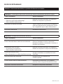
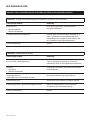
TROUBLE SHOOTING GUIDE
Warning: Isolate supply before working on any part of the electrical system.
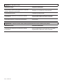
Problem A: Over-current protection (circuit breaker) trips or blows
Probable causes Correction
Electrical fault at:
• connection lead
• damaged heating cable
Locate and rectify the fault and reset or replace
protection.
Protection undersized Re-establish what the current loads are
going to be and install new protection
(NB: if protection is replaced, ensure it is
compatible with the supply cable).
Defective protection Replace
Problem B: residual current device trips
Probable causes Correction
Excessive moisture in junction box Dry out and check seal; replace if necessary.
Perform an insulation resistance test.
Earth fault at:
• connection
• damaged heating cable
Locate and rectify the fault and reset or
replace rcd.
Leakage current too high:
power cable or heating cable too long
Correct problem and re-design.
Contactor bouncing Replace with higher quality contactor
Voltage spikes in power supply network Reset rcd. If condition persists,
use clean power supply.
Defective rcd Replace

18 | nVent.com
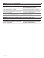
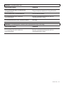
Problem C: Ice/snow not melting
Probable causes Correction
Loss of supply current due to over-currentor
residual current device operating.
Follow procedures outlined in A and B above.
Loss of supply cable continuity Locate and rectify fault.
Incorrect setting or operation of system controls Replace
Incorrect contactor sizing or damaged contactor Rectify
Problem D: Ice/snow begins to melt, but system turns off too soon
Probable causes Correction
Incorrect setting or operation of system. controls. Repair system control unit or
set system controls correctly.

nVent.com | 19
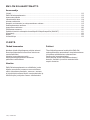
EM2-CM-MAT
Installations- und Betriebshandbuch
Allgemeines ................................................................................................................................................ 19
Freiflächen-Heizsystem EM-2CM-Mat ...................................................................................................... 20
Zubehör ....................................................................................................................................................... 21
Vorbereiten des Untergrundes .................................................................................................................. 21
Vor der Installation zu prüfen .................................................................................................................... 21
Überlegungen zur Auslegung .................................................................................................................... 23
Installation der Freiflächen-Heizmatte ..................................................................................................... 24
Überprüfung der Montage ......................................................................................................................... 27
Oberflächeninstallation ............................................................................................................................. 27
Heizkabelwiderstands- und Isolationsprüfung ........................................................................................ 28
Rinnenbeheizungssystem mit selbstregelndem Heizband GM-2XT ...................................................... 28
Abschließende Arbeiten ............................................................................................................................ 29
Betrieb ......................................................................................................................................................... 30
Fehlersuche ................................................................................................................................................ 30
ALLGEMEINES
Important
Wichtig
Um sicherzustellen, daß das
Freiflächenbeheizungssystem ordnungsgemäß
funktioniert, müssen alle in diesem
Handbuch enthaltenen Anweisungen
genau eingehalten werden. Die Montage
muß außerdem entsprechend den örtlich
geltenden Bestimmungen für elektrische
Beheizungssysteme erfolgen.
Hinweis
Die Freiflächenheizmatte EM2-CM Mat ist eine
elektrische Anlage, die in geeigneter Weise
ausgelegt und ordnungsgemäß montiert
werden muss.
Zur Gewährleistung des ordnungsgemäßen
Betriebs, zum Schutz vor elektrischer Gefährdung
und zum Brandschutz müssen alle Anweisungen
in Bezug auf Auslegung, Montage, Prüfung und
Betrieb eingehalten werden.
Umfang
Dieses Handbuch beschreibt die Installation
der nVent RAYCHEM Freiflächen-Heizmatte
EM2-CM-Mat in Estrich und Sand für dauerhafte
Beanspruchungen.
nVent verfügt darüber hinaus über weitere
Produkte, die für die Verlegung in Asphalt und für
andere Anwendungen geeignet sind.

20 | nVent.com
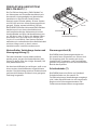
FREIFLÄCHEN-HEIZSYSTEM
EM2-CM-MAT (1)
Die Freiflächen-Heizmatte „EM2-CM-Mat“ ist
ein Heizsystem auf Festwiderstandsbasis mit
konstanter Leistungsabgabe zur dauerhaften
Installation in Estrich oder Sand-Zement-
Gemisch unter Pflaster-platten. Dieses System
mit 230 VAC wird von einem Steuerungseinheit
geregelt. (Regler separat erhältlich.) Bei der
RAYCHEM Freiflächen-Heizmatte EM2-CM-Mat
handelt es sich um eine vorkonfektionierte
und installationsfertige Heizmatte mit einem
Anschlußkabel und einer Heizbandleistung von
ca. 300 W/m² oder 25 W/m. Alle Matten haben
eine Breite von 0,6 m und sind in Längen von
2 m bis 21 m erhältlich. Das System umfasst
außerdem ein vorkonfektioniertes Kaltleiterkabel
mit einer Länge von 4 m, das in einem
Installationsrohr installiert werden muss.
Abstandhalter, Verbindungs-kasten und
Versorgungsleitung (9)
Falls das Heizkabel von der Matte entfernt
werden muss, sorgen die Abstandshalter (VIA-
Strips-PL) dafür, dass der richtige Abstand (100
mm) beibehalten wird.
Um das Anschlußkabel zu verlängern, muß es an
einen zweiten Anschlußkasten angeschlossen
werden. Die Verbindung zwischen Schaltschrank
und Anschluß-kasten wird durch eine geeignete
Zuleitung hergestellt.
Steuerungseinheit (8)
RAYCHEM bietet Steuerungseinheiten an,
die speziell zum Schmelzen von Schnee und
Eis ausgelegt sind. Sie werden mit einem
kombinierten Temperatur- und Feuchtefühler
geliefert und sorgen für einen wirtschaftlichen
Betrieb des Systems.
Schaltschränke (7)
RAYCHEM bietet eine Reihe von Standard-
Schaltschränken an, die speziell für
Freiflächenheizungs-Anwendungen ausgelegt
sind. Jeder Schaltschrank ist mit integriertem
Regler sowie Sicherungsautomaten und
Fehlerstromschutzschaltern ausgestattet.
60 cm
10 cm
Anschlußkabel
Anschluß- und
Heizkabelverbindung
Strona się ładuje...
Strona się ładuje...
Strona się ładuje...
Strona się ładuje...
Strona się ładuje...
Strona się ładuje...
Strona się ładuje...
Strona się ładuje...
Strona się ładuje...
Strona się ładuje...
Strona się ładuje...
Strona się ładuje...
Strona się ładuje...
Strona się ładuje...
Strona się ładuje...
Strona się ładuje...
Strona się ładuje...
Strona się ładuje...
Strona się ładuje...
Strona się ładuje...
Strona się ładuje...
Strona się ładuje...
Strona się ładuje...
Strona się ładuje...
Strona się ładuje...
Strona się ładuje...
Strona się ładuje...
Strona się ładuje...
Strona się ładuje...
Strona się ładuje...
Strona się ładuje...
Strona się ładuje...
Strona się ładuje...
Strona się ładuje...
Strona się ładuje...
Strona się ładuje...
Strona się ładuje...
Strona się ładuje...
Strona się ładuje...
Strona się ładuje...
Strona się ładuje...
Strona się ładuje...
Strona się ładuje...
Strona się ładuje...
Strona się ładuje...
Strona się ładuje...
Strona się ładuje...
Strona się ładuje...
Strona się ładuje...
Strona się ładuje...
Strona się ładuje...
Strona się ładuje...
Strona się ładuje...
Strona się ładuje...
Strona się ładuje...
Strona się ładuje...
Strona się ładuje...
Strona się ładuje...
Strona się ładuje...
Strona się ładuje...
Strona się ładuje...
Strona się ładuje...
Strona się ładuje...
Strona się ładuje...
Strona się ładuje...
Strona się ładuje...
Strona się ładuje...
Strona się ładuje...
Strona się ładuje...
Strona się ładuje...
Strona się ładuje...
Strona się ładuje...
Strona się ładuje...
Strona się ładuje...
Strona się ładuje...
Strona się ładuje...
Strona się ładuje...
Strona się ładuje...
Strona się ładuje...
Strona się ładuje...
Strona się ładuje...
Strona się ładuje...
Strona się ładuje...
Strona się ładuje...
Strona się ładuje...
Strona się ładuje...
Strona się ładuje...
Strona się ładuje...
Strona się ładuje...
Strona się ładuje...
Strona się ładuje...
Strona się ładuje...
Strona się ładuje...
Strona się ładuje...
Strona się ładuje...
Strona się ładuje...
Strona się ładuje...
Strona się ładuje...
Strona się ładuje...
Strona się ładuje...
Strona się ładuje...
Strona się ładuje...
Strona się ładuje...
Strona się ładuje...
Strona się ładuje...
Strona się ładuje...
Strona się ładuje...
Strona się ładuje...
-
 1
1
-
 2
2
-
 3
3
-
 4
4
-
 5
5
-
 6
6
-
 7
7
-
 8
8
-
 9
9
-
 10
10
-
 11
11
-
 12
12
-
 13
13
-
 14
14
-
 15
15
-
 16
16
-
 17
17
-
 18
18
-
 19
19
-
 20
20
-
 21
21
-
 22
22
-
 23
23
-
 24
24
-
 25
25
-
 26
26
-
 27
27
-
 28
28
-
 29
29
-
 30
30
-
 31
31
-
 32
32
-
 33
33
-
 34
34
-
 35
35
-
 36
36
-
 37
37
-
 38
38
-
 39
39
-
 40
40
-
 41
41
-
 42
42
-
 43
43
-
 44
44
-
 45
45
-
 46
46
-
 47
47
-
 48
48
-
 49
49
-
 50
50
-
 51
51
-
 52
52
-
 53
53
-
 54
54
-
 55
55
-
 56
56
-
 57
57
-
 58
58
-
 59
59
-
 60
60
-
 61
61
-
 62
62
-
 63
63
-
 64
64
-
 65
65
-
 66
66
-
 67
67
-
 68
68
-
 69
69
-
 70
70
-
 71
71
-
 72
72
-
 73
73
-
 74
74
-
 75
75
-
 76
76
-
 77
77
-
 78
78
-
 79
79
-
 80
80
-
 81
81
-
 82
82
-
 83
83
-
 84
84
-
 85
85
-
 86
86
-
 87
87
-
 88
88
-
 89
89
-
 90
90
-
 91
91
-
 92
92
-
 93
93
-
 94
94
-
 95
95
-
 96
96
-
 97
97
-
 98
98
-
 99
99
-
 100
100
-
 101
101
-
 102
102
-
 103
103
-
 104
104
-
 105
105
-
 106
106
-
 107
107
-
 108
108
-
 109
109
-
 110
110
-
 111
111
-
 112
112
-
 113
113
-
 114
114
-
 115
115
-
 116
116
-
 117
117
-
 118
118
-
 119
119
-
 120
120
-
 121
121
-
 122
122
-
 123
123
-
 124
124
-
 125
125
-
 126
126
-
 127
127
-
 128
128


Raychem EM2-CM-matto Instrukcja instalacji
- Typ
- Instrukcja instalacji
- Niniejsza instrukcja jest również odpowiednia dla
w innych językach
- Deutsch: Raychem EM2-CM-matto Installationsanleitung
- svenska: Raychem EM2-CM-matto Installationsguide
- français: Raychem EM2-CM-matto Guide d'installation
- dansk: Raychem EM2-CM-matto Installationsvejledning
- Nederlands: Raychem EM2-CM-matto Installatie gids
Powiązane artykuły
-
Raychem EMDR-10 Instrukcja instalacji
-
-
-
-
-
-
-
-
-
Inne dokumenty
-
hidealite 7910446 Instrukcja instalacji
-
STIEBEL ELTRON FTM 150-1050 B Operation Instruction
-
STIEBEL ELTRON FTM 150 B Instrukcja obsługi
-
Sera reptil heat cable Information For Use
-
 nVent RAYCHEM S-20 Splice Kit Instrukcja obsługi
-
ELEKTRA ELEKTRA UltraTec Instrukcja instalacji
-
Anslut FROST PROTECTION CABLE Instrukcja obsługi
-
Megger MIT400/2 Series Instrukcja obsługi
-
Renishaw PH20 Installation & User's Guide
-
Tyco Raychem FROSTGUARD Instrukcja instalacji
