
Gebrauchsanweisung
Instructions for use
Mode d’emploi
Gebruiksaanwijzing
Istruzioni per l’uso
Brugsanvisning
Bruksanvisning
Käyttöohje
Manual de utilização
Instrucciones para el uso
Instrukcje użytkowania
Használati utasítás
ИнструкциЯ за употреба
Návod k použití
Návod na použitie
Instruc∑iuni de utilizare
Инструкции по эксплуатации


3
ENGLISH Instructions for use Page 4
POLSKI Instrukcje użytkowania Strona 26
ČESKY Návod k použití Strana 48
SLOVENSKY Návod na použitie Strana 70
MAGYAR Használati utasítás Oldal 92
РУCCКИЙ
Инcтpyкции по экcплyaтaции Cтpaницa
114
БЪЛГAРCКИ
Инcтpyкция зa yпoтpeбa Cтpaницa
136
ROMANA Instrucţiuni de utilizare Pagina 158
AMD 010/1 - 011/1 - 012/1 - 013/1 - 014/1

4
BEFORE USING THE APPLIANCE
To make the most out of your new appliance,
please read the user instructions carefully and keep
them handy for future consultation.
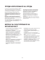
Before using the appliance please follow and
set according to the below indications:
Remote Control (RC) presetting:
Each time the batteries are replaced in the remote
control, the RC is pre-set on Heat pump.
If the air conditioner that you purchased is a
cooling only, then the pre-set on Heat pump will
not bring any changes.
Auto-Restart presetting Function:
To set the auto-restart function, press the
Emergency button (ON/OFF) on the indoor unit
for at least 5 seconds
A buzz sound will signal that the auto-restart
function is set and the air conditioner is in standby.
To cancel the auto-restart function, repeat the
above steps.
SAFETY PRECAUTIONS
• Do not install the appliance if it is connected to
the power supply.
• The Installation and service/repair must be
performed by a qualified technician, in
compliance with the producer's instructions and
following local safety norms. Do not repair or
replace any parts of the appliance unless it is
specifically written in the user instructions.
• The grounding of this appliance is compulsory.
• Make sure that the power supply cord is long
enough to allow the right connection. Do not
use any extension cord for power supply.
• Do not pull the power supply cord to remove it
from the socket.
• Do not twist or press the power supply cord,
and make sure it is not broken.
• Once installation is completed, the electric
components must not be accessible to the users.
• Do not touch the operation buttons when your
hands are wet and don't use the appliance when
you are barefoot.
• Physically or mentally disabled people, children
and people without any experience with the
product are only allowed to use the appliance if
they have had specific training on how to
operate the appliance by a person responsible
for their security and well-being. The appliance
is not intended for use by disabled people and
very young children without supervision.

5
• This appliance has been made of recyclable or
re-usable material. Scrapping must be carried
out in compliance with local waste disposal
regulations. Before scrapping it, make sure to
cut off the mains cord so that the appliance
cannot be re-used.
• For more detailed information on handling and
recycling of this product, contact your local
authorities who deal with the separate collection
of rubbish or the shop where you bought the
appliance.
SCRAPPING OF PACKAGING
• The packaging can be 100% recycled as
confirmed by the recycling symbol . The
various parts of the packaging must not be
dispersed in the environment, but must be
scrapped in line with local authority regulations.
SCRAPPING OF APPLIANCE
• This appliance is marked according to the
European Directive 2002/96/EC, Waste
Electrical and Electronic Equipment (WEEE).
• By ensuring that this product is disposed of
correctly, you will help to prevent potentially
negative consequences for the environment and
for human health.
• The symbol on the product or on the
documents accompanying the product indicates
that this appliance should not be treated as
household waste, but must be given to the
appropriate local gathering place where electric
and electronic appliances are stored and
recycled.
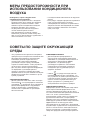
SAFEGUARDING THE ENVIRONMENT
AIR CONDITIONER PRECAUTIONS
Please strictly follow the below instructions:
• Long and direct exposure to cool air might be
harmful to health. It is advisable to set the
louvers in order to avoid direct cool air and
deflect it within the room.
• Prevent the air flow from reaching the gas
burners and stoves.
• Upon malfunctioning first turn the appliance off
by pressing the ON/OFF button on the remote
control, then disconnect it from the mains.
• Do not place any objects on the outdoor unit.
• This product contains Fluorinated Greenhouse
Gases covered by the Kyoto Protocol, the
refrigerant gas being in a hermetically sealed
system. Refrigerant gas: R410a has a
GlobalWarming Potential (GWP) 1975.

6
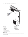
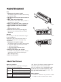
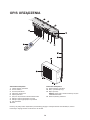
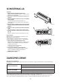
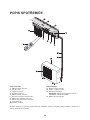
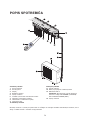
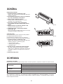
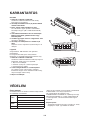
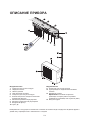
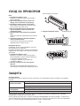
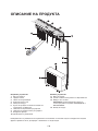
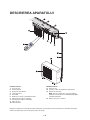
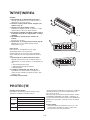
PRODUCT DESCRIPTION
Indoor unit
1. Air Intake
2. Front Panel
3. Display panel
4. Electrical box
5. Air Outlet
6. Filter monitor reset button
7. Vertical Adjustment Louver
8. Horizontal Adjustment Louver
9. Air Filter
10. Remote Control
Outdoor unit
11. Air Intake
12. Pipes and Power Connection Cord
13. Drain Hose
Note: Condensate water drains at COOLING
or DRY operation.
14. Air Outlet
Images in the user instructions are based on external views of standard models, shape and design vary
according to the model.

7
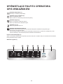
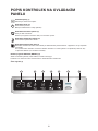
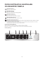
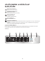
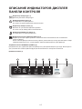
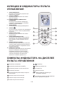
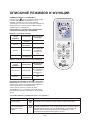
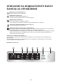
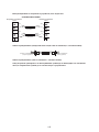
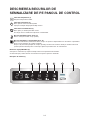
CONTROL PANEL DISPLAY INDICATORS
DESCRIPTION
Temperature indicator (1)
Displays set temperature.
Running indicator (2)
It lights up during operation.
It flashes during outside unit defrosting.
Timer indicator (3)
It lights up during the set time.
It goes off when timer operation ends.
Sleep indicator (4)
It lights up during sleep mode.
Filter monitor indicator (5)
Filter monitor indicator flashes after 240 hours of usage as reminder to clean the filter.
After filter cleaning press the reset button located on the indoor unit behind the front panel in
order to interrupt the flashing of the filter monitor indicator.
Emergency ON/OFF button (6)
Used to control the unit by pressing the button, when the RC is out of work.
Used to set or cancel auto-restart function.
Signal Receptor (7)
1
2 3 4 5 6 7

8
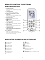
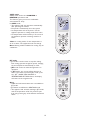
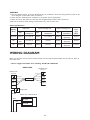
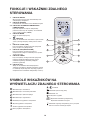
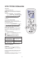
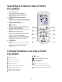
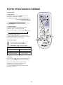
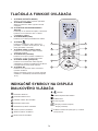
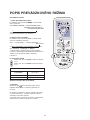
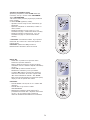
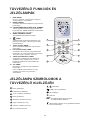
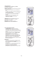
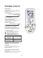
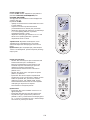
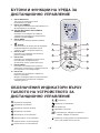
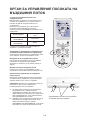
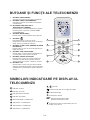
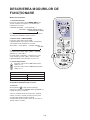
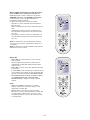
REMOTE CONTROL FUNCTIONS
AND INDICATORS
1. ON/OFF BUTTON
Starts and/or Stops the appliance by pressing
this button.
2. TIMER BUTTON
Sets or cancels the timer operation.
3-4. ROOM TEMPERATURE SETTING
BUTTONS
Used to select the room temperature. Used
to set time in timer mode.
5. MODE BUTTON
Used to select the operation mode.
6. BUTTON
Used to set or cancel 6th sense operation,
also during stand-by.
7. SLEEP BUTTON
Used to set or cancel Sleep Mode operation.
8. FAN BUTTON
Used to select fan speed in sequence auto,
high, medium or low.
9. SWING BUTTON
Used to stop or start vertical adjustment
louver swinging and set the desired up/down
airflow direction.
10. JET BUTTON
Used to start or stop the fast cooling.
(Fast cooling operates at high fan speed with
18°C set temp. automatically).
10
6
5
3
2
1
4
9
8
7
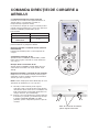
INDICATOR SYMBOLS ON RC DISPLAY
Cooling indicator
Dry indicator
Fan only indicator
Heating indicator
Auto fan speed
High fan speed
Medium fan speed
Low fan speed
indicator
Sleep indicator
Jet indicator
Signal transmission
Display set temperature
Display set timer
Adjust Temperature (±2°C) indicator in 6th
sense mode

9
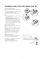
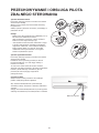
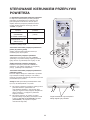
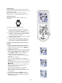
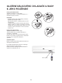
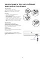
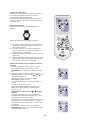
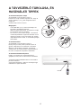
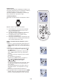
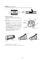
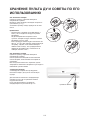
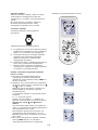
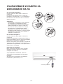
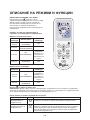
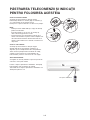
STORAGE AND TIPS FOR USING THE RC
How to insert the batteries
Remove the battery cover in the direction of the
arrow.
Insert new batteries making sure that the (+) and
(-) of battery are matched correctly.
Refit the cover by sliding it back into position.
Note:
• Use 2 LR03 AAA (1.5volt) batteries. Do not use
rechargeable batteries.
Replace batteries with new ones of the same
type when the display becomes dim.
• If the replacement is done within 1 minute, the
remote control will keep original presetting.
However, if you replace batteries taking more
than 3 minutes, all presetting will be cancelled
and timer will display Zero.
How to remove the batteries
Remove the battery cover in the direction of the
arrow.
Press the positive pole of the battery softly with
your fingers, then draw the batteries out of the
compartment.
All this should be done by adults, children are
forbidden to remove the batteries from the
remote control in order to avoid danger of
swallow.
Disposal of the batteries
Please discard the batteries as sorted municipal
waste at the accessible collection point.
To operate the air conditioner, point the remote
control at the signal receptor.
The remote control will operate the air
conditioner at a distance of up to 7m.
Signal receptor

10
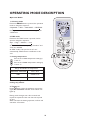
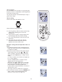
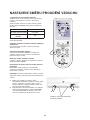
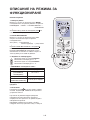
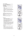
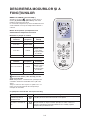
OPERATING MODE DESCRIPTION
Operation Modes:
1. Selecting mode
Each time MODE button is pressed, the operation
mode is changed in sequence:
COOLING → DRY → FAN ONLY → HEATING
↑
Heating mode is not available for cooling only air
conditioners.
2. FAN mode
Each time the "FAN" button is pressed, the fan
speed is changed in sequence:
Auto → High → Medium → Low
↑
At "FAN ONLY" mode, only "High","Medium" and
"Low" are available.
At "DRY" mode, Fan speed is set at "Low"
automatically, "FAN" button is ineffective in this
case.
3. Setting temperature
Press once to raise temperature setting by
1 raise °C
Press once to lower temperature setting by
1 lower °C
*Note: Heating mode is NOT available for
cooling only models.
4. Turning on
Press button, when the appliance receives the
signal, the RUNNING indicator of the indoor unit
lights up.
During mode changes wait a few seconds and
repeat the operation if the unit does not respond
at once.
When selection the heating operation, air flow will
start after 2-5 minutes.
Range of available set temperature
*HEATING, COOLING 18°C~32°C
DRY unable to set
FAN ONLY unable to set

11
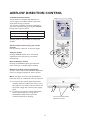
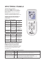
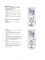
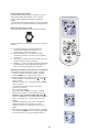
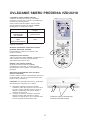
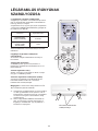
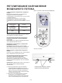
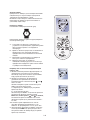
AIRFLOW DIRECTION CONTROL
5. Airflow direction control
Vertical airflow is automatically adjusted to a
certain angle in accordance with the operation
mode after turning on the unit.
The direction of airflow can be also adjusted to
your own requirement by pressing the "SWING"
button of the remote control.
*Heating mode is only available for heat pump
models.
Vertical airflow control (using the remote
control)
Use the remote control to set the flow angles.
Swinging airflow
Pressing "SWING" button once, the vertical
adjustment louver will swing up and down
automatically.
Desired direction airflow
Pressing the "SWING" button again when the
louvers swing to a suitable angle as desired.
Horizontal airflow control (with hands)
Turn the control rods of the horizontal adjustment
louvers to change horizontal air flow as shown.
Note: The shape of the unit may look different
from that of the air conditioner you have selected.
A - Do not turn the vertical adjustment louvers
manually, otherwise malfunction may occur. If
that happens, turn off the unit first and cut off
the power supply, then restore power supply
again.
B - It is better not to let the vertical adjustment
louver tilt downward for a long time at
COOLING or DRY mode to prevent
condensed water from dripping.
Operation mode Direction of airflow
COOLING, DRY horizontal
*HEATING, FAN ONLY downward
control rod of horizontal
adjustment louvers

12
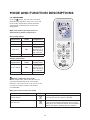
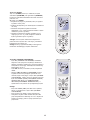
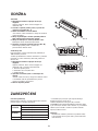
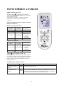
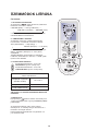
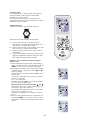
MODE AND FUNCTION DESCRIPTIONS
6th SENSE MODE
Press the button, the unit enters 6th sense
mode directly regardless of the unit is on or off.
In this mode, temperature and fan speed are
automatically set based on the actual room
temperature.
Operation mode and temperature are
determined by indoor temperature.
Heat pump models
Cooling only models
Button is ineffective in Jet mode.
Note: Temperature, airflow and direction are
controlled automatically in 6th sense mode.
However, a decrease or rise of up to 2°C can be
set with the remote control if you still feel
uncomfortable.
What you can do in 6th sense mode
Indoor
temperature
Operation
mode
Target
temperature
21°C or below HEATING 22°C
21°C-23°C FAN ONLY
23°C-26°C DRY
Room
temperature
decrease 1.5°C
after operating
for 3 minutes
Over 26°C COOLING 26°C
Indoor
temperature
Operation
mode
Target
temperature
26°C or below DRY
Room
temperature
decrease 1.5°C
after operating
for 3 minutes
Over 26°C COOLING 26°C
Your feeling button adjustment procedure
Uncomfortable because of unsuitable
air flow volume.
Fan
Indoor fan speed alternates among High, Medium
and Low each time this button is pressed.
Uncomfortable because of unsuitable
flow direction.
Swing
Press it once, the vertical adjustment louver swings
to change vertical airflow direction. Press it again,
swings stops. For horizontal airflow direction please
refer to the chapter "Airflow direction control".

13
SLEEP mode
SLEEP mode can be set in COOLING or
HEATING operation mode.
This function gives you a more comfortable
environment for sleep.
In SLEEP mode,
• The appliance will stop operation automatically
after operating for 8 hours.
• Fan speed is automatically set at low speed.
• Set temperature will rise by max 1°C if the
appliance operates in cooling mode for 2 hours.
• Set temperature will decrease by 3°C at most if
the appliance operates in heating mode for 3
hours.
*Note: In cooling mode, if room temperature is
26°C or above, set temperature will not change.
Note: Heating is NOT available for cooling only air
conditioner.
JET mode
• JET mode is used to start or stop fast cooling.
Fast cooling operates at high fan speed, changing
the set temperature automatically to 18°C.
• JET mode can be set when the appliance is in
operation.
•In JET mode, you can set airflow direction or
timer. If you want to quit from JET mode, press
any - JET , MODE, FAN, ON/OFF or
TEMPERATURE SETTING button, the display
will return to the original mode.
Note:
• SLEEP and 6th Sense buttons are not available in
JET mode.
• JET button is ineffective in HEATING mode.
• The appliance will continue working in JET mode
with set temperature of 18°C if you don't quit
from it by pressing any of the buttons mentioned
above.

14
Timer function
It is convenient to set the timer on by pressing the
button to achieve a comfortable room temperature
at the time you get home.
You can also set timer off automatically to enjoy a
good sleep at night.
Timer-setting
Set the timer when the appliance is off.
Switch-off timer during operation.
A - As time goes by, LCD on remote control only
displays the remaining time not the set
temperature.
B - The previous set time is stored and the next
set time begins with the previous setting.
C - On- timer and Off-timer cannot be set at the
same time.
D - The room may not reach your desired
temperature within the preset time this
depends on the size of the room.
Example: setting the next operation after 9.5
hours
1. Set desired operating mode, temperature and
indoor fan speed, then press the TIMER button;
"h" flashes on display.
2. Point the remote control at the signal receptor
of the indoor unit, press the or button
when "h" flashes. Choose the time you desire,
then press the TIMER button, a "beep" can be
heard.
A - Timer indicator on the indoor unit lights up.
B - "h" stops flashing.
Press the TIMER button, "h" flashes on the
display, then you can set the time.
Each time the or button is pressed,
If the desired time is within 10 hours, the set
time increases or decreases by 0.5 hour;
If desired time is beyond 10 hours, increases or
decreases by 1 hour.
The range can be set is 0.5 hour to 24 hours.
3. To cancel the set timer: press the TIMER button
again, a "beep" can be heard and the timer
indicator on the indoor unit lights off.

15
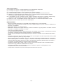
MAINTENANCE
Unit
1. Unplug from the power supply
Turn off the appliance first before disconnecting
from power supply.
2. To remove the front panel pull it outwards
(Fig. A).
3. Wipe with a soft and dry cloth.
Use lukewarm water (below 40°C) to clean if
the appliance is very dirty.
4. Never use substances such as gasoline or
polishing powder to clean the appliance.
5. Never sprinkle water onto the indoor
unit
Dangerous! Electric shock!
6. Refit and close the front panel (Fig. B).
Refit and close the front panel by pushing it
downward.
Air filter
It is necessary to clean the air filter after using it
for about 100 hours.
Clean the air filter every two weeks if the air
conditioner operates in an extremely dusty
environment.
1. Unplug from the power supply
Turn off the appliance first before disconnecting
from power supply and remove the air filter.
1. Open the front panel.
2. Press the handle of the filter gently.
3. Slide out the filter.
2. Cleaning and refitting the air filter.
If the filter is very dirty, clean it with a solution
of lukewarm water and neutral detergent.
After cleaning let it dry.
3. Close the front panel.
Fig. A
Fig. B
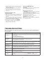
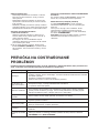
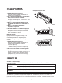
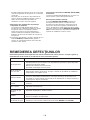
PROTECTION
Operating condition
The protective device maybe trip and stop the
appliance in the cases listed below.
*For Tropical (T3) Climate condition models, the
temperature point is 52°C instead of 43°C.
If the air conditioner runs in COOLING or DRY
mode with door or window opened for a long
time when relative humidity is above 80%, dew
may drip down from the outlet.
Noise pollution
• Install the air conditioner at a place that can bear
its weight in order to operate more quietly.
HEATING
Outdoor air temperature is over 24°C
Outdoor air temperature is below -7°C
Room temperature is over 27°C
COOLING
Outdoor air temperature is over *43°C
Room temperature is below 21°C
DRY Room temperature is below 18°C

16
• Install the outdoor unit at a place where the air
discharged and the operation noise would not
annoy your neighbours.
• Do not place any obstacles in front of the air
outlet of the outdoor unit lest it increases the
noise level.
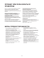
Features of protection device
1. Protection device
Wait at least 3 minutes before restarting the unit
after operation stops or changing mode during
operation.
After connecting to power supply and turning on
the appliance immediately, a delay of 20 seconds
may occur before it starts to operate.
2. If all operation has stopped, press ON/OFF
button again to restart. Timer should be set
again if it has been cancelled.
Features of HEATING mode
Preheating
2-5 minutes are necessary to preheat the indoor
unit at HEATING operation start.
Defrosting (out door unit)
In HEATING operation the appliance will defrost
(de-ice) automatically to raise efficiency.
This procedure usually lasts 2-10 minutes. During
defrosting, fan stops operation.
After defrosting completes, it returns to
HEATING mode automatically.
Note: Heating is NOT available for cooling only
air conditioner models.
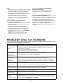
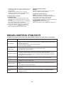
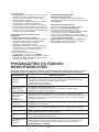
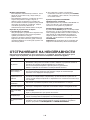
TROUBLESHOOTING
Trouble Analysis
Does not run
• Is the protection device or fuse blown?
• Please wait for 3 minutes and start again, protection device may be preventing
unit to work.
• Are the RC batteries low?
• Is the plug not properly plugged?
No cooling or
heating air
• Is the air filter dirty?
• Are the intakes and outlets of the air conditioner blocked?
• Is the temperature set properly?
Ineffective control
• Has there been a strong interference (from excessive static electricity discharge,
power supply voltage abnormality)? Note that operation will be abnormal, in this
case unplug from the power supply and re-plug after 2-3 seconds.
Does not operate
immediately
• 3 minute delay will occur when changing mode during operation.
Peculiar smell
• This smell may come from another source such as furniture, cigarette etc, which
is sucked in the unit and blown out with the air.
A sound of running
water
• Normal behaviour caused by the flow of refrigerant in the air conditioner.
• Defrosting sound in heating mode.
Cracking sound
• The sound may be generated by the expansion or contraction of the front panel
due to temperature changes.
Mist sprays from
the outlet
• Mist is present in the room with low temperature? Normal behaviour due to
cool air discharged from indoor unit during COOLING or DRY operation
mode.
Operation problems are often due to minor causes that can be found and fixed without
using any tools:

17
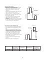
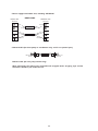
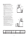
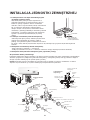
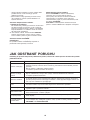
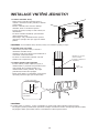
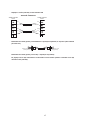
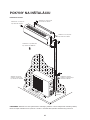
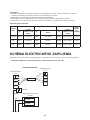
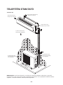
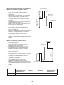
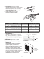
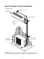
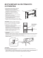
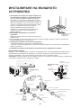
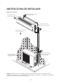
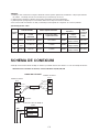
INSTALLATION INSTRUCTIONS
Installation diagram
NOTE: The figure above is only a simple presentation of the unit, it may not match the external
appearance of the product you purchased. Installation must be performed in accordance with the national
wiring standards by authorized service people only.
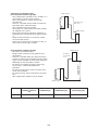
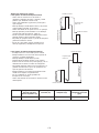
Distance from wall
should be over 50mm
Distance from ceiling
should be over 50mm
Distance from floor
should be over 2000mm
Distance from the wall
should be over 50mm
Air intake distance from
the wall should be over
250mm
Air intake distance from
the wall should be over
250mm
Air outlet distance from the wall
should be over 500mm
Over 250mm

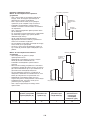
18
Select the best location
Location for Installing Indoor Unit
• Where there is no obstacle near the air outlet
and air can be easily blown to every corner.
• Where piping and wall hole can be easily
arranged.
• Observe the required distance from ceiling and
wall according to the wiring diagram.
• Where the air filter can easily be removed.
• Keep the unit and remote control 1m or more
from television, radio etc.
• To prevent the effects of a fluorescent lamp,
keep the unit as far as possible from it.
• Do not put anything near the air inlet that could
obstruct it.
• In a place that can bear the weight and will not
increase operating noise and vibrations.
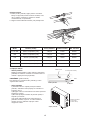
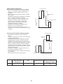
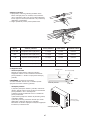
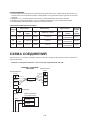
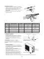
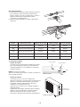
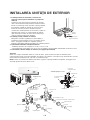
Location for Installing Outdoor Unit
• Install in a convenient and well-ventilated place.
• Avoid installing it where flammable gas could
leak.
• Observe the required distance from the wall.
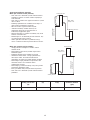
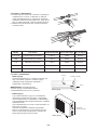
• The distance between Indoor and outdoor unit
should be 5 meters and can go up to maximum
15 meters with additional refrigerant charge.
• Do not install the outdoor unit in a dirty or
greasy place, near a vulcanization gas exit.
• Avoid installing it at the roadside where it could
be soiled with muddy water.
• A fixed base where operating noise will not
increase.
• Where the air outlet is not obstructed.
Model Max. Allowable
Tubing Length at
Shipment (m)
Limit of Tubing
Length (m)
Limit of Elevation
Difference H (m)
Required amount
of additional
refrigerant (g/m)
7K~24K 5 15 5 20
Indoor unit
Pipe length is
15 meters Max.
Outdoor unit
Height should
be less than 5m
Outdoor unit
Pipe length is
15 meters Max.
Indoor unit
Height should be less
than 5m

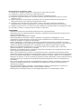
19
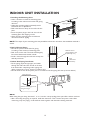
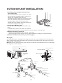
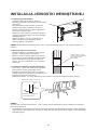
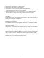
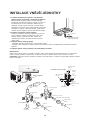
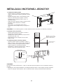
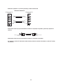
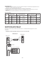
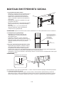
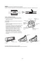
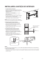
INDOOR UNIT INSTALLATION
1. Installing the Mounting Plate
• Select a location to install the mounting plate
according to the indoor unit location and piping
direction.
• Adjust the mounting plate horizontally with a
horizontal ruler or plumb line.
• Drill holes 32mm in deep on the wall to fix the
plate.
• Insert the plastic plugs in the hole, then fix the
mounting plate with tapping screws.
• Check that the mounting plate is well fixed.
Then drill a hole for piping.
NOTE: The shape of your mounting plate may be different from the one above, but installation method is
similar.
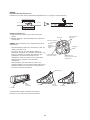
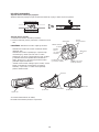
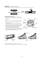
2. Drill a Hole for Piping
• Decide the position of the hole for piping
according to the location of mounting plate.
• Drill a hole on the wall. The hole should slightly
be inclined downward toward outside.
• Install a sleeve through the wall hole to keep the
wall tidy and clean.
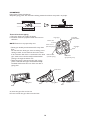
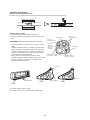
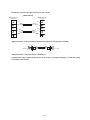
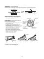
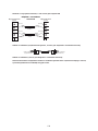
3. Indoor Unit Piping Installation
• Fit the piping (liquid and gas pipe) and cables
through the wall hole from outside or fit them
from inside after completing indoor piping and
cables connections so as to connect to outdoor unit.
• Decide whether saw off the plastic part in accordance with the piping direction (as shown below).
NOTE:
When fixing the pipe along directions 1, 2 or 4, saw the corresponding plastic part off the indoor unit base.
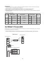
• After connecting the piping as required, install the drain hose. Then connect the power cords. After
connecting, wrap the piping, cords and drain hose together with thermal insulating materials.
Wall hole sleeve
(hard polythene tube
prepared by user)
Indoor
Outdoor
5mm
(downward
inclination)
1
2
3
4
trough
Piping direction
Unloading
piece
Saw the unloading piece off
along the trough
Tapping screw
Mounting plate

20
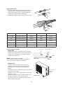
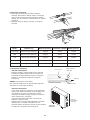
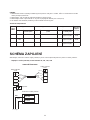
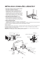
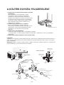
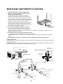
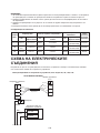
IMPORTANT:
Piping Joints Thermal Insulation:
Wrap the piping joints with thermal insulating materials and then wrap with a vinyl tape.
Thermal Insulation piping:
a. Place the drain hose under the piping.
b. Insulation material: polythene foam over 6mm in
thickness.
NOTE: Drain hose is prepared by user.
• Drain pipe should point downward for easy drain
flow.
Do not twist the drain pipe, leave it sticking out or
waving around, do not immerse the end in water.
If an extension drain hose is connected to the drain
pipe, make sure to be thermally insulated when
passing it through the indoor unit.
• When the piping is directed to the right, piping,
power cord and drain pipe should be thermally
insulated and fixed at the rear of the unit with a
piping fixer.
A. Insert the pipe fixer to the slot.
B. Press to hook the pipe fixer onto the base.
Thermal insulation
Wrapped with vinyl type
Large pipe
Thermally
insulated tube
Small pipe
Power cord 1
(for heat-pump)
Defrost cable
(for heat-pump)
Drain hose
(prepared by user)
Power cord
Base
Piping fixer
Base
Piping fixer
Insert here
Base
Hook here
Large
pipe
Drain
hose
Small
pipe
Large
pipe
Drain
hose
Small
pipe
Strona się ładuje...
Strona się ładuje...
Strona się ładuje...
Strona się ładuje...
Strona się ładuje...
Strona się ładuje...
Strona się ładuje...
Strona się ładuje...
Strona się ładuje...
Strona się ładuje...
Strona się ładuje...
Strona się ładuje...
Strona się ładuje...
Strona się ładuje...
Strona się ładuje...
Strona się ładuje...
Strona się ładuje...
Strona się ładuje...
Strona się ładuje...
Strona się ładuje...
Strona się ładuje...
Strona się ładuje...
Strona się ładuje...
Strona się ładuje...
Strona się ładuje...
Strona się ładuje...
Strona się ładuje...
Strona się ładuje...
Strona się ładuje...
Strona się ładuje...
Strona się ładuje...
Strona się ładuje...
Strona się ładuje...
Strona się ładuje...
Strona się ładuje...
Strona się ładuje...
Strona się ładuje...
Strona się ładuje...
Strona się ładuje...
Strona się ładuje...
Strona się ładuje...
Strona się ładuje...
Strona się ładuje...
Strona się ładuje...
Strona się ładuje...
Strona się ładuje...
Strona się ładuje...
Strona się ładuje...
Strona się ładuje...
Strona się ładuje...
Strona się ładuje...
Strona się ładuje...
Strona się ładuje...
Strona się ładuje...
Strona się ładuje...
Strona się ładuje...
Strona się ładuje...
Strona się ładuje...
Strona się ładuje...
Strona się ładuje...
Strona się ładuje...
Strona się ładuje...
Strona się ładuje...
Strona się ładuje...
Strona się ładuje...
Strona się ładuje...
Strona się ładuje...
Strona się ładuje...
Strona się ładuje...
Strona się ładuje...
Strona się ładuje...
Strona się ładuje...
Strona się ładuje...
Strona się ładuje...
Strona się ładuje...
Strona się ładuje...
Strona się ładuje...
Strona się ładuje...
Strona się ładuje...
Strona się ładuje...
Strona się ładuje...
Strona się ładuje...
Strona się ładuje...
Strona się ładuje...
Strona się ładuje...
Strona się ładuje...
Strona się ładuje...
Strona się ładuje...
Strona się ładuje...
Strona się ładuje...
Strona się ładuje...
Strona się ładuje...
Strona się ładuje...
Strona się ładuje...
Strona się ładuje...
Strona się ładuje...
Strona się ładuje...
Strona się ładuje...
Strona się ładuje...
Strona się ładuje...
Strona się ładuje...
Strona się ładuje...
Strona się ładuje...
Strona się ładuje...
Strona się ładuje...
Strona się ładuje...
Strona się ładuje...
Strona się ładuje...
Strona się ładuje...
Strona się ładuje...
Strona się ładuje...
Strona się ładuje...
Strona się ładuje...
Strona się ładuje...
Strona się ładuje...
Strona się ładuje...
Strona się ładuje...
Strona się ładuje...
Strona się ładuje...
Strona się ładuje...
Strona się ładuje...
Strona się ładuje...
Strona się ładuje...
Strona się ładuje...
Strona się ładuje...
Strona się ładuje...
Strona się ładuje...
Strona się ładuje...
Strona się ładuje...
Strona się ładuje...
Strona się ładuje...
Strona się ładuje...
Strona się ładuje...
Strona się ładuje...
Strona się ładuje...
Strona się ładuje...
Strona się ładuje...
Strona się ładuje...
Strona się ładuje...
Strona się ładuje...
Strona się ładuje...
Strona się ładuje...
Strona się ładuje...
Strona się ładuje...
Strona się ładuje...
Strona się ładuje...
Strona się ładuje...
Strona się ładuje...
Strona się ładuje...
Strona się ładuje...
Strona się ładuje...
Strona się ładuje...
Strona się ładuje...
Strona się ładuje...
Strona się ładuje...
Strona się ładuje...
Strona się ładuje...
Strona się ładuje...
Strona się ładuje...
Strona się ładuje...
-
 1
1
-
 2
2
-
 3
3
-
 4
4
-
 5
5
-
 6
6
-
 7
7
-
 8
8
-
 9
9
-
 10
10
-
 11
11
-
 12
12
-
 13
13
-
 14
14
-
 15
15
-
 16
16
-
 17
17
-
 18
18
-
 19
19
-
 20
20
-
 21
21
-
 22
22
-
 23
23
-
 24
24
-
 25
25
-
 26
26
-
 27
27
-
 28
28
-
 29
29
-
 30
30
-
 31
31
-
 32
32
-
 33
33
-
 34
34
-
 35
35
-
 36
36
-
 37
37
-
 38
38
-
 39
39
-
 40
40
-
 41
41
-
 42
42
-
 43
43
-
 44
44
-
 45
45
-
 46
46
-
 47
47
-
 48
48
-
 49
49
-
 50
50
-
 51
51
-
 52
52
-
 53
53
-
 54
54
-
 55
55
-
 56
56
-
 57
57
-
 58
58
-
 59
59
-
 60
60
-
 61
61
-
 62
62
-
 63
63
-
 64
64
-
 65
65
-
 66
66
-
 67
67
-
 68
68
-
 69
69
-
 70
70
-
 71
71
-
 72
72
-
 73
73
-
 74
74
-
 75
75
-
 76
76
-
 77
77
-
 78
78
-
 79
79
-
 80
80
-
 81
81
-
 82
82
-
 83
83
-
 84
84
-
 85
85
-
 86
86
-
 87
87
-
 88
88
-
 89
89
-
 90
90
-
 91
91
-
 92
92
-
 93
93
-
 94
94
-
 95
95
-
 96
96
-
 97
97
-
 98
98
-
 99
99
-
 100
100
-
 101
101
-
 102
102
-
 103
103
-
 104
104
-
 105
105
-
 106
106
-
 107
107
-
 108
108
-
 109
109
-
 110
110
-
 111
111
-
 112
112
-
 113
113
-
 114
114
-
 115
115
-
 116
116
-
 117
117
-
 118
118
-
 119
119
-
 120
120
-
 121
121
-
 122
122
-
 123
123
-
 124
124
-
 125
125
-
 126
126
-
 127
127
-
 128
128
-
 129
129
-
 130
130
-
 131
131
-
 132
132
-
 133
133
-
 134
134
-
 135
135
-
 136
136
-
 137
137
-
 138
138
-
 139
139
-
 140
140
-
 141
141
-
 142
142
-
 143
143
-
 144
144
-
 145
145
-
 146
146
-
 147
147
-
 148
148
-
 149
149
-
 150
150
-
 151
151
-
 152
152
-
 153
153
-
 154
154
-
 155
155
-
 156
156
-
 157
157
-
 158
158
-
 159
159
-
 160
160
-
 161
161
-
 162
162
-
 163
163
-
 164
164
-
 165
165
-
 166
166
-
 167
167
-
 168
168
-
 169
169
-
 170
170
-
 171
171
-
 172
172
-
 173
173
-
 174
174
-
 175
175
-
 176
176
-
 177
177
-
 178
178
-
 179
179
-
 180
180


Whirlpool AMD 010/1 instrukcja
- Kategoria
- Klimatyzatory typu split
- Typ
- instrukcja
w innych językach
- slovenčina: Whirlpool AMD 010/1 Užívateľská príručka
- română: Whirlpool AMD 010/1 Manualul utilizatorului