
_______________________________________________________________________________________
_______________________________________________________________________________________
SM 4.0 – DISPLAY 10”
USER AND MAINTENANCE BOOK
en
INSIDE: en - it - de - es - fr - pl - ru

_______________________________________________________________________________________
_______________________________________________________________________________________
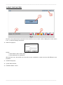
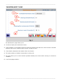
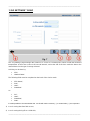
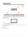
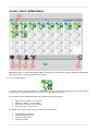
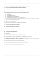
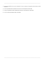
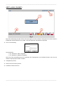
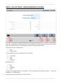
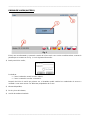
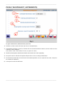
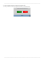
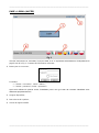
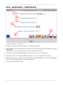
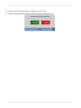
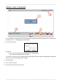
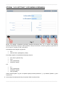
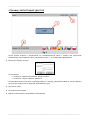
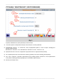
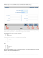
“LOGIN” PAGE (ACCESS)
The hmi, once powered and connected via the serial line to one or more coolers, displays the screen shown
in Pic. 1, with the following information:
1) Button for logging in;
Default:
• Enter “admin” as the “user name”;
• Enter “password” as “password”.
After the first access, the installer can choose the access credentials or create new ones with different access
properties.
2) Available languages;
3) System date and time;
4) Installed software version.

_______________________________________________________________________________________
_______________________________________________________________________________________
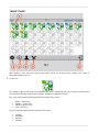
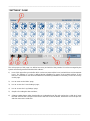
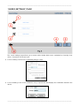
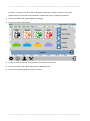
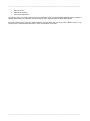
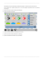
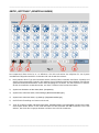
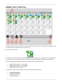
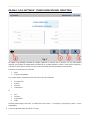
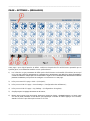
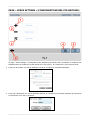
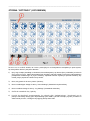
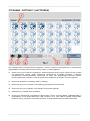
“MAIN” PAGE
After logging in, you access the "Main" page which shows an overview of the system, each cooler is
represented here by an icon.
1) Cooler icon;
The number in the top left-hand corner identifies the cooler, the background colour of the box indicates the
area to which it belongs, transparency indicates a machine configured as single.
The colour of the stylised fan represents the four states of the cooler:
• Offline - (black icon);
• Standby - (yellow icon);
• Running - (green icon);
• Fault - (red icon).
The box at the top right shows the function of the cooler:
• Cooling;
• Ventilation;
• Exhaust;
• Cleaning.

_______________________________________________________________________________________
_______________________________________________________________________________________
Finally, the bottom right-hand box identifies the "master" cooler within an area.
Acting on the icon you access the menu dedicated to the cooler for specific adjustments.
2) Icon to access the "Settings" page;
3) Icon to access the key;
4) Icon to access the page allowing you to change your password;
5) Icon to access the "Maintenance" page;
6) Icon to return to the "Login" page.

_______________________________________________________________________________________
_______________________________________________________________________________________
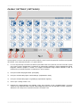
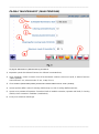
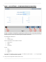
“SETTINGS” PAGE
The main purpose of this page is to define how many and which of the potential 31 coolers managed by the
system are actually present and with which address:
1) Icons of this type allow you to define which coolers are present (blue icons) and which are not (transparent
icons). The address of a cooler is defined during installation by means of the multiple selector on the
board. It is advisable to note down the addresses used during installation so that they can be set correctly
on this page.
2) Icon to return to the "Main" page;
3) Icon to access the "Users Settings" page ;
4) Icon to access the "Log Settings" page;
5) Graphics for setting the date and time;
6) Software update button. After downloading an "UpdatePackage" file and copying it to a USB stick, insert
the USB stick into the USB port on the back of the HMI. Press the button, wait for the end of the process
and then remove the USB stick.

_______________________________________________________________________________________
_______________________________________________________________________________________
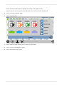
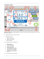
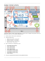
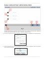
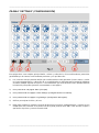
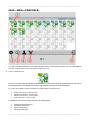
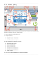
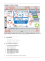
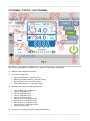
“STATUS” PAGE
Typically, the user only accesses this page in the event of an error, in which case the fan icon is red. The
information available is:
1) Modbus Address of the selected machine;
2) Status of the cooler:
• Offline - (black icon);
• Standby - (yellow icon);
• Running - (green icon);
• Fault - (red icon).
3) Drop-down menu for configuration as:
• "Not Installed';
• “Area 1” (area slave);
• “Area 2” (area slave);
• “Area 3” (area slave);
• “Area 4” (area slave);
• “Area 1 Master” (area master);
• “Area 2 Master” (area master);
• “Area 3 Master” (area master);
• “Area 4 Master” (area master);
• “Single”.
4) Icon for setting the Cooling function;

_______________________________________________________________________________________
_______________________________________________________________________________________
5) Icon for setting the Cooling Auto function;
6) Icon for setting the Ventiltion function;
7) Icon for setting the Exhaust function;
8) Icon for setting the Cleaning function;
This particular mode can be performed in four ways:
• Manually;
• On hourly programming;
• For reached limit "Clean Scheduler";
• Automatically, at the end of each cooling cycle.
9) Icon for setting the Auxiliary option, this option refers to a 230Vac contact that can be freely managed;
10) Cooler on/off button;
11) Notification of the need for maintenance;
12) Temperature measured outside the building;
13) Temperature measured inside the building;
14) Target temperature (Set temperature);
15) Humidity measured inside the building;
16) Target Humidity (Set humidity);
17) Water level;
18) Icon to access the Timer page (Time schedule);
19) Icon for bringing a cooler that has gone offline back online;
20) Display and adjustment of fan rotation speed; the arrow on the right implements an increase, the arrow
on the left a decrease;
21) Measurement of current drawn by the cooler motor;
22) Fault Code accompanied by a short description;
23) Icon to return to the "Main" page.

_______________________________________________________________________________________
_______________________________________________________________________________________
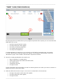
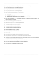
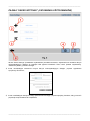
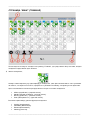
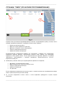
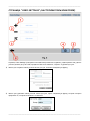
“TIMER” PAGE (TIME SCHEDULE)
The timer page (Time schedule) allows you to program the operation of the system, you can create time slots
within which you can set:
• On which days the function is active;
• The time at which the action applies;
• The action you want to programme;
• The rotation speed of the fan;
• The set point in temperature.
Consistent definitions of a time for an "On" and one for an "Off" define an operating range. An exception
is "Clean" where only the start time needs to be defined, as the duration of the function is set in the
"Maintenance" page, via the variable "Clean duration" expressed in minutes.
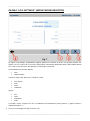
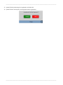
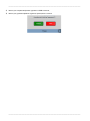
1) Menus for creating operating time slots must be set:
• Days of operation, on a weekly basis;
• A time expressed in hours before and minutes after;
• Fan rotation speed;
• Temperature set point;
• The type of action.
Once the parameters have been defined, use the icon with the green tick to confirm your choices, and the icon
with the red cross to cancel your entries;
2) What was defined in the menu in step 1, once saved, is summarised in a line that shows:
• The days of the week on which the action applies;
• The time at which the action applies;
• The type of action;

_______________________________________________________________________________________
_______________________________________________________________________________________
• Rotational speed;
• Temperature Set point.
Each time slot, once created, can be modified at a later date by clicking on the green icon to the left of the time
slot; to delete a time slot, click on the red icon to the right of the time slot.
NOTE: The system knows the day of the week corresponding to the date. The panel is equipped with RTC
and buffer cap to maintain the time in case of power failure.

_______________________________________________________________________________________
_______________________________________________________________________________________
“MAINTENANCE” PAGE
The "Maintenance" page allows you to:
1) Set when to display the maintenance banner;
2) Clean Scheduler, i.e. the number of hours of continuous operation, after which the "Clean" function is activated.
Minimum value 1 hour, maximum value 72 hours, in steps of 1 hour;
3) Clean duration, determines the duration of the clean function;
4) This option enables or disables cleaning after a cooling cycle;
5) This item allows you to set the maximum permitted humidity level, above which cleaning is converted to
ventilation;
6) Icons for language selection.

_______________________________________________________________________________________
_______________________________________________________________________________________
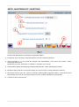
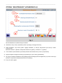
“USERS SETTINGS” PAGE
The "Users Settings" page allows you to create, edit or delete HMI access credentials by choosing "User
name", "Password" and access level.
1) Icon for creating a new access credential by filling in a form;
2) Icon for deleting a new access credential, using a special form that displays the credentials entered in the
device;

_______________________________________________________________________________________
_______________________________________________________________________________________
3) Icon for editing a new access credential, using a form similar to the one in point 1;
4) Icon to import login credentials from another device via USB;
5) Icon for exporting login credentials from another device, via USB;
6) Icon to return to the "Main" page.

_______________________________________________________________________________________
_______________________________________________________________________________________
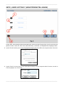
“LOG SETTINGS” PAGE
The "Log Settings" page manages the creation of a .csv file on a monthly basis, which records the measured
temperatures of the active coolers at 30-second intervals, and at the end of the hour sends the data to the
network based on the type of storage selected.
Archiving can be done by:
• “FTP”;
• “Shared Folder”.
The following fields must be completed on the basis of the choice made:
• “FTP Server”;
• “Port”;
• “User”;
• “Password”.
Or:
• “PC”;
• “User”;
• “Password”;
• “Path”.
it is also possible to choose whether the .csv file will use the comma (“,”) or a semicolon (“;”) as separators.
1) Icon for saving data from flash to ram;
2) Icon for saving the log file to a USB stick;

_______________________________________________________________________________________
_______________________________________________________________________________________
3) Icon for deleting log files stored in ram.

_______________________________________________________________________________________
_______________________________________________________________________________________
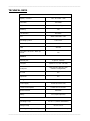
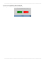
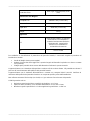
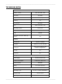
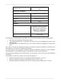
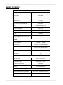
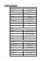
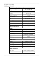
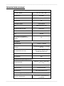
TECHNICAL DATA
System Resources
Display – Colours
10.1” TFT 16:9 – 64K
Resolution
1024×600
Brightness
200 Cd/m2 typ.
Dimming
Yes
Touchscreen
Resistive
CPU
ARM Cortex A8 1 GHz
Operating System
Linux 3.12
Flash
4 GB
RAM
512 MB
Real Time Clock, RTC Back-up,
Buzzer
Yes
Interface
Ethernet port
1 (port 0 - 10/100)
USB port
1 (Host v. 2.0, max. 500 mA)
Serial port
1 (RS-232, RS-485, RS-422,
software configurable)
SD card
No
Expansion
No
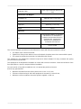
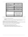
Ratings
Power supply
24 Vdc (10 to 32 Vdc)
Current Consumption
0.38 A max. at 24 Vdc
Input Protection
Automatic
Battery
Yes (Supercapacitor)
Environment Conditions
Operating Temp
0 to 50 °C (vertical installation)
Storage Temp
-20°C to +70°C
Operating / Storage Humidity
5-85% RH, non-condensing

_______________________________________________________________________________________
_______________________________________________________________________________________
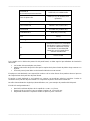
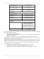
Protection Class
IP66, Type 2 and 4X (front); IP20
(rear)
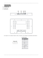
Dimensions and Weights
Faceplate LxH
282×197 mm (11.10×7.80“)
Cutout AxB
271x186 mm (10.66x7.32")
Depth D+T
29+6 mm (1.14+0.19”)
Weight
1.0 Kg
Approvals
CE
Emission EN 61000-6-4, Immunity
EN 61000-6-2 for installation in
industrial environments Emission
EN 61000-6-3, Immunity EN
61000-6-1 for installation in
residential environments
UL
cULus: UL508
The correct installation procedure must be followed to comply with front panel protection ratings:
• The edges of the cutout must be flat;
• Tighten each fixing screw until the corner of the plastic faceplate comes into contact with the panel;
• The cutout for the panel must be the size indicated in this manual.
The equipment is not intended for continuous exposure to direct sunlight. This may accelerate the ageing
process of the front panel film.
The equipment is not intended for installation in contact with corrosive chemicals. Check the resistance of the
front panel film to a specific compound before installation.
Do not use tools of any kind (screwdrivers, etc.) to operate the panel touchscreen.
IP66 is only guaranteed if:
• Maximum deviation from the surface plane to be cut out: <= 0.5 mm;
• Thickness of the housing in which the equipment is mounted: 1.5 mm to 6 mm;
• Maximum surface roughness where the gasket is applied: <=120 um.

_______________________________________________________________________________________
_______________________________________________________________________________________
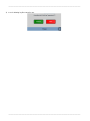
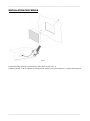
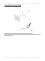
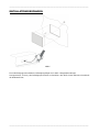
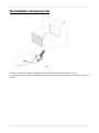
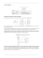
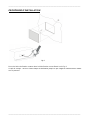
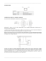
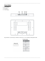
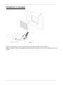
INSTALLATION PROCEDURE
Pic.6
Position the fixing brackets contained in the fixing kit as shown in Pic. 6.
Tightening torque: 75 Ncm. Tighten each fixing screw until the corner of the frame is in contact with the panel.

_______________________________________________________________________________________
_______________________________________________________________________________________
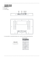
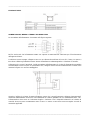
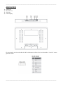
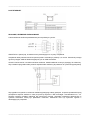
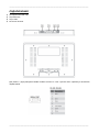
CONNECTIONS
1) Serial Port;
2) Ethernet Port;
3) USB Port;
4) Power Supply.
To operate with a 2-wire RS485 modbus, pins 4-3 and 8-7 must be jumpered externally.

_______________________________________________________________________________________
_______________________________________________________________________________________
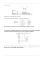
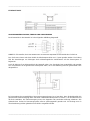
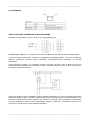
ETHERNET PORT
POWER SUPPLY, EARTHING AND SHIELDING
The terminal block of the power supply unit is shown in the following figure.
NOTE: Ensure that the power supply has sufficient power capacity to operate the equipment.
The unit must always be earthed with a minimum cable size of 1.5 sq. mm. Earthing helps to limit the effects
of noise due to electromagnetic interference on the control system.
Also earth terminal 3 on the power supply terminal block. The power supply circuit may be floating or earthed.
In the latter case, earth the common power source as shown in the figure with a dotted line.
When using the floating power scheme, note that the operator panels internally connect the power supply
common to earth with a 1 MΩ resistor in parallel with a 4.7 nF capacitor. The power supply must have double
or reinforced insulation. All electronic devices in the control system must be properly earthed. Earthing must
be carried out in accordance with the applicable regulations.

_______________________________________________________________________________________
_______________________________________________________________________________________
4250.295 Edition 21 Vers.
Strona się ładuje...
Strona się ładuje...
Strona się ładuje...
Strona się ładuje...
Strona się ładuje...
Strona się ładuje...
Strona się ładuje...
Strona się ładuje...
Strona się ładuje...
Strona się ładuje...
Strona się ładuje...
Strona się ładuje...
Strona się ładuje...
Strona się ładuje...
Strona się ładuje...
Strona się ładuje...
Strona się ładuje...
Strona się ładuje...
Strona się ładuje...
Strona się ładuje...
Strona się ładuje...
Strona się ładuje...
Strona się ładuje...
Strona się ładuje...
Strona się ładuje...
Strona się ładuje...
Strona się ładuje...
Strona się ładuje...
Strona się ładuje...
Strona się ładuje...
Strona się ładuje...
Strona się ładuje...
Strona się ładuje...
Strona się ładuje...
Strona się ładuje...
Strona się ładuje...
Strona się ładuje...
Strona się ładuje...
Strona się ładuje...
Strona się ładuje...
Strona się ładuje...
Strona się ładuje...
Strona się ładuje...
Strona się ładuje...
Strona się ładuje...
Strona się ładuje...
Strona się ładuje...
Strona się ładuje...
Strona się ładuje...
Strona się ładuje...
Strona się ładuje...
Strona się ładuje...
Strona się ładuje...
Strona się ładuje...
Strona się ładuje...
Strona się ładuje...
Strona się ładuje...
Strona się ładuje...
Strona się ładuje...
Strona się ładuje...
Strona się ładuje...
Strona się ładuje...
Strona się ładuje...
Strona się ładuje...
Strona się ładuje...
Strona się ładuje...
Strona się ładuje...
Strona się ładuje...
Strona się ładuje...
Strona się ładuje...
Strona się ładuje...
Strona się ładuje...
Strona się ładuje...
Strona się ładuje...
Strona się ładuje...
Strona się ładuje...
Strona się ładuje...
Strona się ładuje...
Strona się ładuje...
Strona się ładuje...
Strona się ładuje...
Strona się ładuje...
Strona się ładuje...
Strona się ładuje...
Strona się ładuje...
Strona się ładuje...
Strona się ładuje...
Strona się ładuje...
Strona się ładuje...
Strona się ładuje...
Strona się ładuje...
Strona się ładuje...
Strona się ładuje...
Strona się ładuje...
Strona się ładuje...
Strona się ładuje...
Strona się ładuje...
Strona się ładuje...
Strona się ładuje...
Strona się ładuje...
Strona się ładuje...
Strona się ładuje...
Strona się ładuje...
Strona się ładuje...
Strona się ładuje...
Strona się ładuje...
Strona się ładuje...
Strona się ładuje...
Strona się ładuje...
Strona się ładuje...
Strona się ładuje...
Strona się ładuje...
Strona się ładuje...
Strona się ładuje...
Strona się ładuje...
Strona się ładuje...
Strona się ładuje...
Strona się ładuje...
Strona się ładuje...
Strona się ładuje...
-
 1
1
-
 2
2
-
 3
3
-
 4
4
-
 5
5
-
 6
6
-
 7
7
-
 8
8
-
 9
9
-
 10
10
-
 11
11
-
 12
12
-
 13
13
-
 14
14
-
 15
15
-
 16
16
-
 17
17
-
 18
18
-
 19
19
-
 20
20
-
 21
21
-
 22
22
-
 23
23
-
 24
24
-
 25
25
-
 26
26
-
 27
27
-
 28
28
-
 29
29
-
 30
30
-
 31
31
-
 32
32
-
 33
33
-
 34
34
-
 35
35
-
 36
36
-
 37
37
-
 38
38
-
 39
39
-
 40
40
-
 41
41
-
 42
42
-
 43
43
-
 44
44
-
 45
45
-
 46
46
-
 47
47
-
 48
48
-
 49
49
-
 50
50
-
 51
51
-
 52
52
-
 53
53
-
 54
54
-
 55
55
-
 56
56
-
 57
57
-
 58
58
-
 59
59
-
 60
60
-
 61
61
-
 62
62
-
 63
63
-
 64
64
-
 65
65
-
 66
66
-
 67
67
-
 68
68
-
 69
69
-
 70
70
-
 71
71
-
 72
72
-
 73
73
-
 74
74
-
 75
75
-
 76
76
-
 77
77
-
 78
78
-
 79
79
-
 80
80
-
 81
81
-
 82
82
-
 83
83
-
 84
84
-
 85
85
-
 86
86
-
 87
87
-
 88
88
-
 89
89
-
 90
90
-
 91
91
-
 92
92
-
 93
93
-
 94
94
-
 95
95
-
 96
96
-
 97
97
-
 98
98
-
 99
99
-
 100
100
-
 101
101
-
 102
102
-
 103
103
-
 104
104
-
 105
105
-
 106
106
-
 107
107
-
 108
108
-
 109
109
-
 110
110
-
 111
111
-
 112
112
-
 113
113
-
 114
114
-
 115
115
-
 116
116
-
 117
117
-
 118
118
-
 119
119
-
 120
120
-
 121
121
-
 122
122
-
 123
123
-
 124
124
-
 125
125
-
 126
126
-
 127
127
-
 128
128
-
 129
129
-
 130
130
-
 131
131
-
 132
132
-
 133
133
-
 134
134
-
 135
135
-
 136
136
-
 137
137
-
 138
138
-
 139
139
-
 140
140


w innych językach
Powiązane artykuły
Inne dokumenty
-
 VTS HMI BASIC 2 HY VENTUS Compact Instrukcja obsługi
-
OJ Electronics OJ-Air2-HMI-20T Instrukcja obsługi
-
Asus WL-600g Instrukcja obsługi
-
Nice Automation O-Box Instrukcja obsługi
-
Kingston DATATRAVELER LOCKER G2/DTLPG2 Instrukcja obsługi
-
Hoover HOZP9177BI Instrukcja obsługi
-
ATEN US3344I Skrócona instrukcja obsługi
-
 Hach Polymetron 9526 Basic User Manual
-
Ingo MMU002D Instrukcja obsługi
-
Banner Bike Bull AGM+SLA Quick Manual

