
USER MANUAL
CEILING FAN
WINDLIGHT EASY


4
WINDLIGHT EASY
INDEX
ENGLISH
MECANIC PROBLEMS 6
LOCATION AND INSTALLATION REQUIREMENTS 6
SECURITY INSTRUCTIONS 6
ELECTRIC PROBLEMS 7
CAUTIONS AND WARNINGS 7
LIST OF PARTS 7
INSTALLATION PREPARATION 8
INSTALLATION INSTRUCTIONS 8
ELECTRIC CONNECTION 8
POST INSTALLATION 9
FIXING THE MOUNTING BRACKET 9
MOUNT AND HANG THE FAN 10
BLADE ASSEMBLY 11
INSTALLING THE LIGHT KIT 11
MOUNTING THE ROSETTE 12
ESPAÑOL
PROBLEMAS MECÁNICOS 13
REQUISITOS DE UBICACIÓN E INSTALACIÓN 13
INSTRUCCIONES DE SEGURIDAD 13
PROBLEMAS ELÉCTRICOS 14
PRECAUCIONES Y ADVERTENCIAS 14
LISTA DE PARTES 14
PREPARACIÓN DE LA INSTALACIÓN 15
INSTRUCCIONES DE INSTALACIÓN 15
CONEXIÓN ELÉCTRICA 15
INSTALACIÓN DE LA TIJA 16
FIJACIÓN DEL SOPORTE DE MONTAJE 16
MONTAR Y COLGAR EL VENTILADOR 17
ENSAMBLAJE DE LAS ASPAS 18
INSTALACIÓN DEL KIT DE LUZ 18
MONTAJE DEL FLORÓN 19
PORTUGUÊS
PROBLEMAS MECÂNICOS 20
REQUISITOS DE LOCALIZAÇÃO E INSTALAÇÃO 20
INSTRUÇÕES DE SEGURANÇA 20
PROBLEMAS ELÉTRICOS 21
CUIDADOS E ADVERTÊNCIAS 21
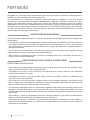
LISTA DE PEÇAS 21
PREPARAÇÃO DE INSTALAÇÃO 22
INSTRUÇÕES DE INSTALAÇÃO 22
CONEXÃO ELÉTRICA 22
PÓS-INSTALAÇÃO 23
FIXANDO O SUPORTE DE MONTAGEM 23
MONTE E PENDURE O VENTILADOR 24
CONJUNTO DE LÂMINA 25
INSTALANDO O KIT DE LUZ 25
MONTAGEM DA ROSETA 26
FRANÇAIS
PROBLÈMES MÉCANIQUES 27
EMPLACEMENT ET D'INSTALLATION 27
CONSIGNES DE SÉCURITÉ 27
PROBLÈMES ÉLECTRIQUES 28
PRÉCAUTIONS ET AVERTISSEMENTS 28
LISTE DES PIÈCES 28
PRÉPARATION DE L'INSTALLATION 29
BRANCHEMENT ELECTRIQUE 29
INSTRUCTIONS D'INSTALLATION 29
POST-INSTALLATION 30
FIXATION DU SUPPORT DE MONTAGE 30
MONTER ET ACCROCHER LE 31
VENTILATEUR 31
ASSEMBLAGE DE LA LAME 32
INSTALLATION DU KIT D'ÉCLAIRAGE 32
MONTAGE DE LA ROSACE 33

5
ITALIANO
PROBLEMI MECCANICI 34
UBICAZIONE E REQUISITI DI INSTALLAZIONE 34
ISTRUZIONI DI SICUREZZA 34
PROBLEMI ELETTRICI 35
PRECAUZIONI E AVVERTENZE 35
ELENCO DELLE PARTI 35
PREPARAZIONE DELL'INSTALLAZIONE 36
ISTRUZIONI PER L'INSTALLAZIONE 36
COLLEGAMENTO ELETTRICO 36
POST INSTALLAZIONE 37
FISSAGGIO DELLA STAFFA DI MONTAGGIO 37
MONTA E APPENDI IL VENTILATORE 38
GRUPPO LAME 39
INSTALLAZIONE DEL KIT LUCI 39
MONTAGGIO DELLA ROSETTA 40
DEUTSCH
MECHANISCHE PROBLEME 41
INSTALLATIONSVORAUSSETZUNGEN 41
SICHERHEITSHINWEISE 41
ELEKTRISCHE PROBLEME 42
VORSICHTS- UND WARNHINWEISE 42
LISTE DER TEILE 42
INSTALLATIONSVORBEREITUNG 43
ELEKTRISCHER ANSCHLUSS 43
INSTALLATIONSANLEITUNG 43
NACH DER INSTALLATION 44
BEFESTIGUNG DER MONTAGEHALTERUNG 44
MONTIEREN UND HÄNGEN SIE 45
KLINGENMONTAGE 46
INSTALLATION DES BELEUCHTUNGSKITS 46
ROSETTE MONTIEREN 47
NEDERLANDS
MECHANISCHE PROBLEMEN 48
LOCATIE- EN INSTALLATIEVEREISTEN 48
BEVEILIGINGSINSTRUCTIES 48
ELEKTRISCHE PROBLEMEN 49
VOORZORGSMAATREGELEN EN WAARSCHUWINGEN 49
LIJST MET ONDERDELEN 49
INSTALLATIE VOORBEREIDING 50
ELEKTRISCHE AANSLUITING 50
INSTALLATIE INSTRUCTIES 50
NA INSTALLATIE 51
DE MONTAGEBEUGEL BEVESTIGEN 51
MONTEER EN HANG DE VENTILATOR 52
MES MONTAGE 53
DE LICHTSET INSTALLEREN 53
DE ROZET MONTEREN 54
POLSKI
PROBLEMY MECHANICZNE 55
WYMAGANIA DOTYCZĄCE LOKALIZACJI I INSTALACJI 55
INSTRUKCJE BEZPIECZEŃSTWA 55
PROBLEMY ELEKTRYCZNE 56
PRZESTROGI I OSTRZEŻENIA 56
LISTA CZĘŚCI 56
PRZYGOTOWANIE INSTALACJI 57
POŁĄCZENIE ELEKTRYCZNE 57
INSTRUKCJE INSTALACJI 57
PO INSTALACJI 58
MOCOWANIE WSPORNIKA MONTAŻOWEGO 58
ZAMONTUJ I ZAWIEŚ WENTYLATOR 59
ZESPÓŁ OSTRZA 60
INSTALOWANIE ZESTAWU OŚWIETLENIOWEGO 60
MONTAŻ ROZETY 61
INDEX
WINDLIGHT EASY

ENGLISH
6
Thank you for choosing our ceiling fan. Before using the appliance, and to ensure the best
use, please read these instructions carefully.
The safety precautions included in this document reduce the risk of death, injury, and
electric shock when properly followed. Keep the manual in a safe place for future reference,
along with the complete warranty card, sales receipt, and package. If applicable, please
forward these instructions to the next owner of the appliance. Always follow basic safety
precautions and accident prevention measures when using an electrical appliance. We do
not assume any responsibility for the breach of these requirements by the customer.
SECURITY INSTRUCTIONS
LOCATION AND INSTALLATION REQUIREMENTS
When using any electrical appliance, basic safety precautions should always be observed.
• This appliance is not designed for use by persons with reduced physical, sensory or mental
disabilities or lack of experience and knowledge, unless they are under supervision or have
been instructed in the safe use of the appliance and understand the dangers involved.
• Children do not recognize the dangers that can occur when operating a ceiling fan
• Keep children away from ceiling fans.
• Do not expose the ceiling fan to rain or moisture. Do not use the ceiling fan outdoors or with
wet hands.
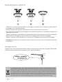
• According to safety regulations, the lowest point of the fan blade must be at least 2.3 m (7
ft) above the ground.
• Make sure the chosen location does not allow the rotating fan blades to come into contact
with anything.
• Make sure the ceiling joists are solid and large and strong enough to support the weight
of the fan.
• To reduce the risk of re, electric shock, or personal injury, make sure the fan mounting
bracket is connected directly to the building structure. DO NOT mount it in a distribution
box.
• The mounting bracket must be rmly bolted to a supporting structure, for example a
concrete ceiling, a steel structure or a wooden frame. If a wooden frame is added, it must
be rmly nailed or screwed between two rafters.
• To reduce the risk of personal injury and property damage, do not bend or damage the fan
rod or blades when handling or installing them.
• Make sure the ceiling fan is securely attached to the ceiling. All set screws should be
checked and retightened as necessary prior to fan operation.
ENGLISH
MECANIC PROBLEMS

7
ENGLISH
CAUTIONS AND WARNINGS
• Use only CREATE replacement parts.
• To reduce the risk of personal injury, connect the fan directly to the building support
structure in accordance with these instructions and use only the supplied hardware.
• To avoid possible electrical shock, before installing your fan, disconnect power by turning
off the circuit breakers in the outlet box and associated wall switch.
• All wiring must be in accordance with national and local electrical codes and ANSI / NFPA
70. If you are unfamiliar with wiring, contact a qualied electrician.
• To reduce the risk of personal injury, do not bend the blade clamping system when
installing, balancing, or cleaning the fan. Never insert foreign objects between the rotating
fan blades.
• To reduce the risk of re, electric shock, or motor damage, do not use a solid state speed
control with this fan. Use only CREATE speed controls
Note: The important safety precautions and instructions in this manual are not intended to
cover all possible conditions and situations that may occur. It should be understood that
common sense and caution are necessary factors in the installation and operation of this
fan.
• Always turn off the power before repairing the ceiling fan and turn off the circuit breaker
that feeds the power to the light. To avoid possible electric shock, make sure the electricity
is turned off at the fuse box or circuit breaker panel before wiring.
• The fan, mounting bracket, and light kit must be grounded. Make sure all spliced
connections are adequately insulated.
• Check and conrm that all connections are correct and secure. When all electrical
connections are made, store all cables in an orderly fashion.
• Do not attempt to control this fan from any wall switch or remote control that is not
approved by the manufacturer for use with this fan. DO NOT use a solid state controller.
Use of an unapproved remote control or wall switch will void the warranty.
• Do not connect the ceiling fan to a dimmer or dimmer.
ELECTRIC PROBLEMS
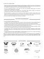
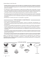
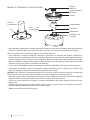
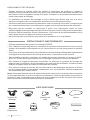
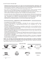
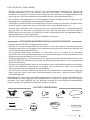
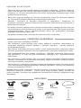
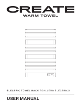
LIST OF PARTS
Blade hitch
Expansion
bolts
BladesFloron ShankMounting
bracket
Motor Tulipa Chains

ENGLISH
8
INSTALLATION INSTRUCTIONS
• Mark the correct position of the holes and x the mounting bracket using the screws with
metal plugs or screws and washers suitable for the type of ceiling chosen.
• Check the correct installation of the bracket before hanging the fan. This plate must
support the full weight of the fan.
• To avoid personal injury and damage,
make sure the place to hang the blades
leaves a clearance of 2.3 m from the
ground and 76 cm from any walls or
obstacles.
• Make sure the mounting bracket is
securely attached to the building
structure and can support the full weight
of the fan.
INSTALLATION PREPARATION
76 cm of
separation
between
the wall or
obstacle.
2.3 m from
the blades
to the
ground
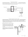
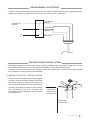
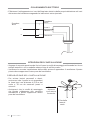
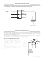
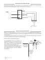
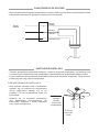
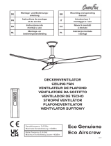
ELECTRIC CONNECTION
• Make the connection between the cables of the electrical installation of your home and the
cables of the fan motor following the instructions below.
Take
ground
Take
ground
L
N
Light L
Neutral N
Motor L

9
ENGLISH
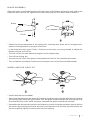
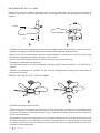
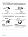
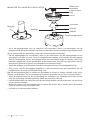
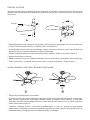
• Remove the bolt from the seatpost, removing the pin and pass the nial (crown molding)
and hood through the hanger bar. Next, route the fan motor wires through the inside of the
hanger bar. Tighten the hanger bar to the engine and insert the bolt and pin.
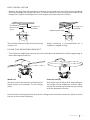
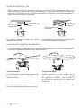
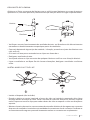
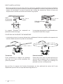
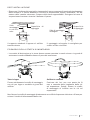
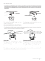
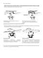
POST INSTALLATION
Support
surface
Traditional
mounting
style
The standard mount hangs from the ceiling
using a rod.
Support
surface
Angle mount style
Angle mounting is recommended for a
vaulted or angled ceiling.
• The outlet box and beam must be securely mounted and capable of reliably supporting at
least the weight of the fan.
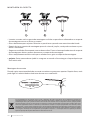
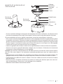
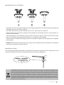
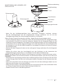
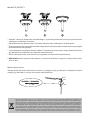
FIXING THE MOUNTING BRACKET
Wood roof
Securely attach the mounting bracket with
wood screws and washers to the ceiling
joints.
Concrete ceiling
Drill holes with an 8mm drill, depending on
the length of the expansion screws. Next,
secure the mounting bracket to the ceiling
with the expansion screws.
Do not x the mounting bracket directly on ceilings with a thickness less than 10mm to avoid
the risk of the screw loosening.
20°

ENGLISH
10
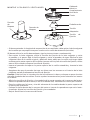
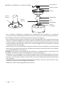
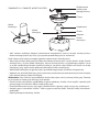
Locking
pin
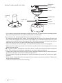
MOUNT AND HANG THE FAN Electrical
wiring
Floron
Ball coupling
Embellisher
Screw
Adapter
Fixing screw
Locking
pin
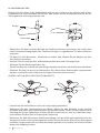
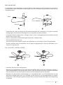
• If you want to extend the suspension length of your fan, you must remove the hanging ball
from the rod provided for use with the extension rod (included).
(If you want to use the downrod, follow the instructions below.)
• To remove the hanging ball, loosen the hanging ball set screw and remove the pin and
bolt. Lower the hanging ball and remove the stopper pin. Slide the hanging ball out of the
original rod and slide it down the longest rod (it should be noted that the top of the rod has
a hole for the set screw, use this hole when inserting the set screw).
• Insert the stopper pin into the top of the extended rod and lift off the hanging ball.
• Make sure the stopper pin aligns with the slots on the inside of the hanging ball, securely
tighten the set screw.
Tip: To make it easier to feed the wires into the bar, wrap some electrical tape around the
wires. This will help you hold them together as you insert them into the bar.
• Loosen set screws and washer on top of motor housing. Remove the pins from the bar (if
you haven't already). Insert the rosette through the bar.
• Pass the cables through the bar and pull the excess cables from the top of the bar to tight-
en them.
• Place the bar inside the motor housing and insert the pins you removed earlier. Tighten the
set screws and washers.
• Lower the rosette onto the motor housing.

11
ENGLISH
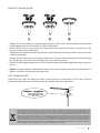
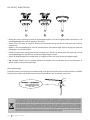
• Check the correct operation of the ceiling fan, checking that there are no strange move-
ments or misalignments in any part of the fan.
• In the event that any type of hum / vibration can be seen, you can proceed to adjust the
blades with the anti-roll kit.
• The anti-roll kit has self-adhesive weights and u-shaped clips.
• Turn off the ceiling fan.
• You can put the clip in the center of any blade and check if the vibration decreases.
• Turn on the fan and check. If there are no changes, turn off the fan and add another.
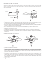
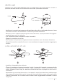
• Install the bulb (not included).
• Attach the lampshade to the motor by inserting the glass neck into the light xture, keeping
two spring clips inside the glass neck. Pull the glass shade towards the third spring clip.
Push the third clip to t inside the glass and push the glass towards the mounter.
• Assemble the decorative keychain and extension chains from the hardware bag to the fan
pull chains by inserting the end of the chain into the chain link. Conrm that the chains are
secure by pulling lightly on both chains on the coupling.
Align the holes in the blade bracket with the holes in the blades and motor body and screw
them into place, but do not tighten the screws until they are all in place and screwed in.
BLADE ASSEMBLY
INSTALLING THE LIGHT KIT
12
12
Screw
Blade

ENGLISH
12
• Raise the rosette up to the mounting bracket and align the loosened screws in the mount-
ing bracket with the holes in the rosette.
• Rotate the n to adjust. Reinsert the screws and secure with a screwdriver.
• Once you have the mounting bracket secured to the junction box you can proceed to hang
the fan.
• Hold the fan rmly with both hands. Pass the rod through the mounting bracket opening
and let the ball rest on the mounting bracket.
• Rotate the ball coupling until it lines up with the tab on the mounting bracket.
• Tip: Someone else should help you hold the ladder and hand you the fan after you get on it.
MOUNTING THE ROSETTE
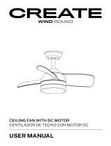
123
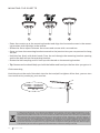
Chain mounting
Hook the pin at the end of the chain into the slot and pull to tighten. After that, you can turn
it on to electricity and enjoy your new fan.
In compliance with Directives: 2012/19/EU and 2015/863/EU on the restriction of the use of dangerous substances in elec-
tric and electronic equipment as well as their waste disposal. The symbol with the crossed dustbin shown on the package
indicates that the product at the end of its service life shall be collected as separate waste. Therefore, any products that
have reached the end of their useful life must be given to waste disposal centres specialising in separate collection of
waste electrical and electronic equipment, or given back to the retailer at the time of purchasing new similar equipment,
on a one for one basis. The adequate separate collection for the subsequent start-up of the equipment sent to be recycled,
treated and disposed of in an environmentally compatible way contributes to preventing possible negative effects on the
environment and health and optimises the recycling and reuse of components making up the apparatus. Abusive disposal
of the product by the user involves application of the administrative sanctions according to the laws.

13
ESPAÑOL
Gracias por elegir nuestro ventilador de techo. Antes de utilizar el aparato, y para garantizar
el mejor uso, lea atentamente estas instrucciones.
Las precauciones de seguridad incluidas en este documento reducen el riesgo de muerte,
lesiones y descargas eléctricas cuando se cumplen correctamente. Guarde el manual en un
lugar seguro para futuras consultas, junto con la tarjeta de garantía completa, el recibo de
compra y el paquete. Si corresponde, transmita estas instrucciones al próximo propietario
del aparato. Siga siempre las precauciones básicas de seguridad y las medidas de prevención
de accidentes cuando utilice un aparato eléctrico. No asumimos ninguna responsabilidad
por el incumplimiento de estos requisitos por parte del cliente.
INSTRUCCIONES DE SEGURIDAD
REQUISITOS DE UBICACIÓN E INSTALACIÓN
Al utilizar cualquier aparato eléctrico, siempre se deben observar las precauciones básicas
de seguridad.
• Este electrodoméstico no está diseñado para que lo utilicen personas con discapacidades
físicas, sensoriales o mentales reducidas o con falta de experiencia y conocimiento, a
menos que estén bajo supervisión o hayan recibido instrucciones sobre el uso seguro del
electrodoméstico y comprendan los peligros involucrados.
• Los niños no reconocen los peligros que pueden ocurrir al operar un ventilador de techo
• Mantenga a los niños alejados de los ventiladores de techo.
• No exponga el ventilador de techo a la lluvia ni a la humedad. No use el ventilador de techo
al aire libre o con las manos mojadas.
• De acuerdo con las normas de seguridad, el punto más bajo de la paleta del ventilador debe
estar al menos a 2,3 m (7 pies) del suelo.
• Asegúrese de que la ubicación elegida no permita que las aspas giratorias del ventilador
entren en contacto con algún objeto.
• Asegúrese de que las vigas del techo sean sólidas y sucientemente grandes y fuertes
para soportar el peso del ventilador.
• Para reducir el riesgo de incendio, descarga eléctrica o lesiones personales, asegúrese de
que el soporte de montaje del ventilador esté conectado directamente a la estructura del
edicio. NO lo monte en una caja de distribución.
• El soporte de montaje debe atornillarse rmemente a una estructura portante, por ejemplo,
un techo de hormigón, una estructura de acero o un marco de madera. Si se agrega un
marco de madera, debe clavarse o atornillarse rmemente entre dos vigas.
• Para reducir el riesgo de lesiones personales y daños a la propiedad, no doble ni dañe la
varilla ni las aspas del ventilador cuando las manipule o instale.
• Asegúrese de que el ventilador de techo esté bien sujeto al techo. Todos los tornillos de
jación deben revisarse y volverse a apretar cuando sea necesario antes de la operación
del ventilador.
ESPAÑOL
PROBLEMAS MECÁNICOS

14 ESPAÑOL
PRECAUCIONES Y ADVERTENCIAS
• Utilice sólo piezas de repuesto CREATE.
• Para reducir el riesgo de lesiones personales, conecte el ventilador directamente a la
estructura de soporte del edicio de acuerdo con estas instrucciones y use solo el hardware
suministrado.
• Para evitar una posible descarga eléctrica, antes de instalar su ventilador, desconecte la
energía apagando los disyuntores de la caja de salida y el interruptor de pared asociado.
• Todo el cableado debe estar de acuerdo con los códigos eléctricos nacionales y locales y
con ANSI / NFPA 70. Si no está familiarizado con el cableado, contacte con un electricista
cualicado.
• Para reducir el riesgo de lesiones personales, no doble el sistema de sujeción de las aspas
al instalar, equilibrar o limpiar el ventilador. Nunca inserte objetos extraños entre las aspas
giratorias del ventilador.
• Para reducir el riesgo de incendio, descarga eléctrica o daños al motor, no utilice un control
de velocidad de estado sólido con este ventilador. Use solo controles de velocidad CREATE
Nota: Las importantes precauciones e instrucciones de seguridad de este manual no
pretenden cubrir todas las posibles condiciones y situaciones que puedan ocurrir. Debe
entenderse que el sentido común y la precaución son factores necesarios en la instalación y
operación de este ventilador.
• Siempre apague la energía antes de reparar el ventilador de techo y apague el disyuntor
que alimenta la energía a la luz. Para evitar una posible descarga eléctrica, asegúrese de
que la electricidad esté apagada en la caja de fusibles o en el panel del disyuntor antes de
realizar el cableado.
• El ventilador, el soporte de montaje y el juego de luces deben estar conectados a la toma
tierra. Asegúrese de que todas las conexiones empalmadas estén adecuadamente aisladas.
• Verique y conrme que todas las conexiones sean correctas y seguras. Cuando todas las
conexiones eléctricas estén hechas, guarde todos los cables de manera ordenada.
• No intente controlar este ventilador desde ningún interruptor de pared o control remoto que
no esté aprobado por el fabricante para su uso con este ventilador. NO use un controlador
de estado sólido. El uso de un interruptor de pared o control remoto no aprobado anulará
la garantía.
• No conecte el ventilador de techo a un atenuador o regulador.
PROBLEMAS ELÉCTRICOS
LISTA DE PARTES
Enganche de
aspas
Tornillos de
expansión
Aspas
Florón Tija
Soporte de
montaje
Motor
Tulipa Cadenas

15
ESPAÑOL
INSTRUCCIONES DE INSTALACIÓN
• Marcar la posición correcta de los oricios y jar el soporte de montaje mediante los
tornillos con taco metálico o tornillos y arandelas adecuados al tipo de techo elegido.
• Verique la correcta instalación del soporte antes de colgar el ventilador. Esta placa debe
soportar todo el peso del ventilador.
• Para evitar lesiones personales y daños,
asegúrese de que el lugar para colgar
las aspas deje un espacio libre de 2,3 m
del suelo y 76 cm de cualquier pared u
obstáculo.
• Asegúrese de que el soporte de montaje
esté bien sujeta a la estructura del
edicio y pueda soportar todo el peso del
ventilador.
PREPARACIÓN DE LA INSTALACIÓN
76 cm de
separación
entre la pared
u obstáculo.
2,3 m de
las aspas al
suelo
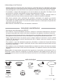
CONEXIÓN ELÉCTRICA
• Realice la conexión entre los cables de la instalación eléctrica de su hogar y los cables del
motor del ventilador siguiendo las siguientes indicaciones.
Toma tierra
Toma tierra
L
N
Luz L
Neutro N
Motor L

16 ESPAÑOL
• Quite el perno de la tija, quitando el pasador y pase el orón (moldura del techo) y la
capota del motor a través de la barra de suspensión. Luego, pase los cables del motor del
ventilador a través del interior de la barra de suspensión. Apriete la barra de suspensión al
motor e inserte el perno y el pasador.
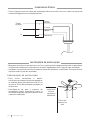
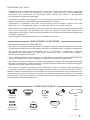
INSTALACIÓN DE LA TIJA
Supercie de
apoyo
Estilo de
montaje
tradicional
El montaje estándar cuelga del techo
mediante una varilla.
Superficie
de apoyo
Estilo de montaje
en ángulo
Se recomienda el montaje en ángulo para
un techo abovedado o en ángulo.
• La caja de salida y la viga deben estar montadas de forma segura y ser capaces de soportar
de manera conable al menos el peso del ventilador.
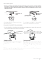
FIJACIÓN DEL SOPORTE DE MONTAJE
Techo de madera
Fije rmemente el soporte de montaje con
tornillos para madera y arandelas a las
juntas del techo.
Techo de hormigón
Realice agujeros con un taladro de 8
mm, según la longitud de los tornillos
de expansión. Después, je el soporte
de montaje al techo con los tornillos de
expansión.
No je el soporte de montaje directamente en techos con un grosor inferior a 10 mm para
evitar el riesgo de que el tornillo se aoje.
20°

17
ESPAÑOL
MONTAR Y COLGAR EL VENTILADOR Cableado
eléctrico
Florón
Acoplamiento
de la bola
Embellecedor
Tornillo
Pasador de
bloqueo
Adaptador
Tornillo de
jación
Pasador
de
bloqueo
• Si desea extender la longitud de suspensión de su ventilador, debe quitar la bola colgante
de la varilla que se proporciona para usarla con la varilla de extensión (incluida).
(Si desea utilizar la varilla descendente, siga las instrucciones a continuación).
• Para quitar la bola colgante, aoje el tornillo de jación de la bola colgante y retire
el pasador y el perno. Baje la bola colgante y retire el pasador de tope. Deslice la bola
colgante fuera de la varilla original y deslícela hacia abajo por la varilla más larga (debe
notarse que la parte superior de la varilla tiene un oricio para el tornillo de jación; utilice
este oricio cuando coloque el tornillo de jación).
• Inserte el pasador de tope en la parte superior de la varilla extendida y levante la bola
colgante.
• Asegúrese de que el pasador de tope se alinee con las ranuras en el interior de la bola
colgante, apriete rmemente el tornillo de jación.
Consejo: Para facilitar la introducción de los cables en la barra, coloque un poco de cinta
aislante alrededor de los cables. Esto le ayudará a mantenerlos juntos mientras los inserta
en la barra.
• Aoje los tornillos de jación y la arandela de la parte superior de la carcasa del motor.
Retire los pasadores de la barra (si no lo ha hecho aún). Introduzca el orón por la barra.
• Pase los cables por la barra y tire del sobrante de los cables desde la parte superior de
la barra para ajustarlos.
• Coloque la barra dentro de la carcasa del motor e inserte los pasadores que retiró ante-
riormente. Ajuste los tornillos de jación y las arandelas.
• Baje el orón hacia la carcasa del motor.

18 ESPAÑOL
• Compruebe el correcto funcionamiento del ventilador de techo, revisando que no se ob-
serven movimientos extraños o desajustes en alguna pieza del ventilador.
• En el caso de que se pueda apreciar algún tipo de zumbido/vibración, puede proceder a
ajustar las aspas con el kit antibalanceo.
• El kit antibalanceo dispone de contrapesos autoadhesivos y clips en forma de “u”.
• Apague el ventilador de techo.
• Puede poner el clip en el centro de cualquier aspa y revisar si la vibración disminuye.
• Encienda el ventilador y compruebe. Si no se aprecian cambios, apague el ventilador y
añada otro.
• Instale la bombilla (no incluida).
• Fije la tulipa al motor insertando el cuello de vidrio en el artefacto de iluminación,
manteniendo dos clips de resorte dentro del cuello del vidrio. Tire de la pantalla de vidrio
hacia el tercer clip de resorte. Empuje el tercer clip para que encaje dentro del vidrio y
empuje el vidrio hacia el montador.
• Ensamble el llavero decorativo y las cadenas de extensión de la bolsa de hardware a las
cadenas de tracción del ventilador insertando el extremo de la cadena en el acoplamiento
de la cadena. Conrme que las cadenas estén sujetas tirando ligeramente de ambas
cadenas en el acoplamiento.
Alinee los oricios del soporte de las aspas con los oricios de las aspas y del cuerpo del
motor y atorníllelas en su sitio, pero no apriete los tornillos hasta que estén todas coloca-
das y atornilladas.
ENSAMBLAJE DE LAS ASPAS
INSTALACIÓN DEL KIT DE LUZ
12
12
Tornillo
Aspa

19
ESPAÑOL
• Levante el orón hasta el soporte de montaje y alinee los tornillos aojados en el soporte
de montaje con los oricios del orón.
• Gire el orón para ajustarlo. Reinserte los tornillos y fíjelos con un destornillador.
• Una vez tenga el soporte de montaje asegurado a la caja de conexiones puede proceder
a colgar el ventilador.
• Agarre el ventilador con rmeza con ambas manos. Pase la barra por la apertura del so-
porte de montaje y deje que la bola se apoye en el soporte de montaje.
• Gire el acoplamiento de la bola hasta que se alinee con la pestaña del soporte de montaje.
• Consejo: Otra persona debería ayudarle para sostener la escalera de mano y alcanzarle
el ventilador una vez se haya subido a esta.
MONTAJE DEL FLORÓN
123
Montaje de cadenas
Enganche la clavija del extremo de la cadena en la ranura y tire para ajustarlo. Después, ya
pordrá encenderlo a la electricidad y disfrutar de su nuevo ventilador.
En cumplimiento de las directivas: 2012/19 / UE y 2015/863 / UE sobre la restricción del uso de sustancias peligrosas en
equipos eléctricos y electrónicos, así como su eliminación de residuos. El símbolo con el cubo de basura cruzado que se
muestra en el paquete indica que el producto al nal de su vida útil se recogerá como residuo separado. Por lo tanto, cualquier
producto que haya llegado al nal de su vida útil debe entregarse a centros de eliminación de residuos especializados en la
recogida selectiva de equipos eléctricos y electrónicos de desecho, o devolverse al minorista al momento de comprar equipos
nuevos similares, en uno para Una base. La recolección separada adecuada para la posterior puesta en marcha de los equipos
enviados para ser reciclados, tratados y eliminados de una manera compatible con el medio ambiente contribuye a prevenir
posibles efectos negativos sobre el medio ambiente y la salud y optimiza el reciclaje y la reutilización de los componentes
que componen el aparato. La eliminación abusiva del producto por parte del usuario implica la aplicación de las sanciones
administrativas de acuerdo con las leyes.

20 PORTUGUÊS
Obrigado por escolher nosso ventilador de teto. Antes de usar o aparelho, e para garantir o
melhor uso, leia atentamente estas instruções.
As precauções de segurança incluídas neste documento reduzem o risco de morte,
ferimentos e choque elétrico quando devidamente seguidas. Guarde o manual em local
seguro para referência futura, junto com o cartão de garantia completo, recibo de venda e
embalagem. Se aplicável, encaminhe estas instruções ao próximo proprietário do aparelho.
Sempre siga as precauções básicas de segurança e as medidas de prevenção de acidentes
ao usar um aparelho elétrico. Não assumimos qualquer responsabilidade pela violação
destes requisitos por parte do cliente.
INSTRUÇÕES DE SEGURANÇA
REQUISITOS DE LOCALIZAÇÃO E INSTALAÇÃO
Ao usar qualquer aparelho elétrico, as precauções básicas de segurança devem sempre ser
observadas.
• Este aparelho não foi projetado para ser usado por pessoas com deciência física, sensorial
ou mental reduzida ou com falta de experiência e conhecimento, a menos que estejam
sob supervisão ou tenham sido instruídas no uso seguro do aparelho e compreendam os
perigos envolvidos.
• As crianças não reconhecem os perigos que podem ocorrer ao operar um ventilador de teto
• Mantenha as crianças longe dos ventiladores de teto.
• Não exponha o ventilador de teto à chuva ou umidade. Não use o ventilador de teto ao ar
livre ou com as mãos molhadas.
• De acordo com os regulamentos de segurança, o ponto mais baixo da pá do ventilador deve
estar pelo menos 2,3 m (7 pés) acima do solo.
• Certique-se de que o local escolhido não permite que as pás rotativas do ventilador
entrem em contato com nada.
• Certique-se de que as vigas do teto sejam sólidas, grandes e fortes o suciente para
suportar o peso do ventilador.
• Para reduzir o risco de incêndio, choque elétrico ou ferimentos pessoais, certique-se de
que o suporte de montagem do ventilador esteja conectado diretamente à estrutura do
edifício. NÃO monte em uma caixa de distribuição.
• O suporte de montagem deve ser rmemente aparafusado a uma estrutura de suporte, por
exemplo, um teto de concreto, uma estrutura de aço ou uma moldura de madeira. Se uma
moldura de madeira for adicionada, ela deve ser rmemente pregada ou aparafusada entre
duas vigas.
• Para reduzir o risco de ferimentos pessoais e danos materiais, não dobre ou danique a
haste ou as pás do ventilador ao manuseá-los ou instalá-los.
• Certique-se de que o ventilador de teto esteja rmemente conectado ao teto. Todos os
parafusos de xação devem ser vericados e reapertados conforme necessário antes da
operação do ventilador.
PORTUGUÊS
PROBLEMAS MECÂNICOS
Strona jest ładowana ...
Strona jest ładowana ...
Strona jest ładowana ...
Strona jest ładowana ...
Strona jest ładowana ...
Strona jest ładowana ...
Strona jest ładowana ...
Strona jest ładowana ...
Strona jest ładowana ...
Strona jest ładowana ...
Strona jest ładowana ...
Strona jest ładowana ...
Strona jest ładowana ...
Strona jest ładowana ...
Strona jest ładowana ...
Strona jest ładowana ...
Strona jest ładowana ...
Strona jest ładowana ...
Strona jest ładowana ...
Strona jest ładowana ...
Strona jest ładowana ...
Strona jest ładowana ...
Strona jest ładowana ...
Strona jest ładowana ...
Strona jest ładowana ...
Strona jest ładowana ...
Strona jest ładowana ...
Strona jest ładowana ...
Strona jest ładowana ...
Strona jest ładowana ...
Strona jest ładowana ...
Strona jest ładowana ...
Strona jest ładowana ...
Strona jest ładowana ...
Strona jest ładowana ...
Strona jest ładowana ...
Strona jest ładowana ...
Strona jest ładowana ...
Strona jest ładowana ...
Strona jest ładowana ...
Strona jest ładowana ...
Strona jest ładowana ...
Strona jest ładowana ...
Strona jest ładowana ...
-
 1
1
-
 2
2
-
 3
3
-
 4
4
-
 5
5
-
 6
6
-
 7
7
-
 8
8
-
 9
9
-
 10
10
-
 11
11
-
 12
12
-
 13
13
-
 14
14
-
 15
15
-
 16
16
-
 17
17
-
 18
18
-
 19
19
-
 20
20
-
 21
21
-
 22
22
-
 23
23
-
 24
24
-
 25
25
-
 26
26
-
 27
27
-
 28
28
-
 29
29
-
 30
30
-
 31
31
-
 32
32
-
 33
33
-
 34
34
-
 35
35
-
 36
36
-
 37
37
-
 38
38
-
 39
39
-
 40
40
-
 41
41
-
 42
42
-
 43
43
-
 44
44
-
 45
45
-
 46
46
-
 47
47
-
 48
48
-
 49
49
-
 50
50
-
 51
51
-
 52
52
-
 53
53
-
 54
54
-
 55
55
-
 56
56
-
 57
57
-
 58
58
-
 59
59
-
 60
60
-
 61
61
-
 62
62
-
 63
63
-
 64
64


w innych językach
- español: Create WINDLIGHT EASY Manual de usuario
- italiano: Create WINDLIGHT EASY Manuale utente
- Deutsch: Create WINDLIGHT EASY Benutzerhandbuch
- português: Create WINDLIGHT EASY Manual do usuário
- français: Create WINDLIGHT EASY Manuel utilisateur
- Nederlands: Create WINDLIGHT EASY Handleiding
Powiązane dokumenty
-
Create WINDLIGHT EASY Instrukcja obsługi
-
 Create Wind Round Ceiling Fan Instrukcja obsługi
-
Create Windlight Fold DC Instrukcja obsługi
-
Create Wind Stylance DC Instrukcja obsługi
-
 Create WINDLIGHT CURVE DC Instrukcja obsługi
-
Create Wind Tube Ceiling Fan Instrukcja obsługi
-
Create WINDLIGHT Instrukcja obsługi
-
Create Industrial Fan Instrukcja obsługi
-
 Create Electric Tower Rack Instrukcja obsługi


Inne dokumenty
-
LIVARNO 359555 Instrukcja obsługi
-
 CaseFan Eco Airscrew Instrukcja obsługi
-
Eglo SUSALE Instrukcja obsługi
-
-
-
-
Tristar VE-5810 Instrukcja obsługi
-
Tristar VE-5815 Instrukcja obsługi
-
AEG D-VL 5667 Instrukcja obsługi
-
Inspire Java Instrukcja obsługi
