Indesit KN3N65SA/BG instrukcja
- Kategoria
- Piekarniki
- Typ
- instrukcja
Niniejsza instrukcja jest również odpowiednia dla

English
GB
Operating Instructions
COOKER AND OVEN
Contents
Operating Instructions,1
Description of the appliance-Control Panel,1
Description of the appliance-Overall view,2
Installation,3
Start-up and use,7
Cooking modes,8,
Precautions and tips,12
Care and maintenance,13
Assistance,13
KN3N65SA/BG
Polski
PL
Instrukcja obsługi
KUCHENKA I PIEKARNIK
Spis treści
Instrukcja obsługi,1
Opis urządzenia-Panel sterowania,1
Opis urządzenia-Widok ogólny,2
Instalacja,14
Uruchomienie i użytkowanie,18
Użytkowanie piekarnika,19
Zalecenia i środki ostrożności,24
Konserwacja i utrzymanie,25
Serwis Techniczny,25
P L
BG
4
5
2
1
3
6
7
8
Description of the appliance
Control panel
GB
1.Electronic cooking programmer
2.TIMER button
3.THERMOSTAT knob
4.SELECTOR knob
5.THERMOSTAT indicator light
6.Electric HOTPLATE control knob
7.Hob BURNER control knob
8.ELECTRIC HOTPLATE indicator light
PL
Opis urządzenia
Panel kontrolny
1.Programator elektroniczny
2.Przycisk MINUTNIKA
3.Pokrętło TERMOSTATU
4.Pokrętło PROGRAMÓW PIEKARNIKA
5.Lampka kontrolna TERMOSTATU
6.Pokrętła ELEKTRYCZNYCH PÓL GRZEJNYCH
7.Pokrętło PALNIKÓW PŁYTY GRZEJNEJ
8.Lapmka kontrolna ELEKTRYCZNYCH PÓL GRZEJNYCH
RS
Инструкции за употреба
ЕЛЕКТРИЧЕСКА ПЕЧКА И ФУРНА
Резюме
Инструкции за употреба,1
Описание на уреда- Управляващ панел,1
Описание на уреда-Общ преглед,2
Инсталиране,26
Пуск и експлоатация, 30
Използване на фурната,33
Предпазни мерки и препоръки,35
Поддръжка и почистване,36
Техническо обслужване,36
Описание на уреда
Управляващ панел
BG
1. Електронна готвене програмист
2. TIMER
3. Бучка термостат
4. ключа за избор
5. Светлинен индикатор на термостата
6. Копчето за управление на електрически котлон
7. Копчето за управление на Котлон горелката
8. Светлинен индикатор на електрически котлон
Български

2
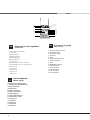
1.ELECTRIC HOTPLATE
2. Hob Grid
3.Control panel
4.Sliding grill rack
5.DRIPPING pan
6.Adjustable foot
7. Hob burner
8.Containment surface for spills
9.GUIDE RAILS for the sliding racks
10.position 5
11.position 4
12.position 3
13.position 2
14.position 1
Description of the appliance
Overall view
GB
PL
1.Elektryczna płyta grzejna
2 Ruszta płyty podpalnikowej
3.Panel kontrolny
4.Półka ruszt
5.Półka brytfanna
6.Nóżki regulowane
7.Palnik gazowy
8. Płyta podpalnikowa
9. Prowadnice półek
10. pozycja 5
11.pozycja 4
12.pozycja 3
13.pozycja 2
14.pozycja 1
Opis urządzenia
Widok ogólny
1 .Електрически котлони
2 .Горна решетка
3 .Командно табло
4 .Решетка
5 .Тава
6 .Регулируеми крачета
7. Газови горелки
8 .Плот
9. BOДAЧИ за двата
10.Положение 5
11 Положение 4
12 Положение 3
13 Положение 2
14 Положение 1
Описание на уреда
Общ преглед
BG
2
1
3
4
5
6
6
10
11
12
13
14
9
8
7

GB
3
! Before operating your new appliance please read
this instruction booklet carefully. It contains important
information concerning the safe installation and
operation of the appliance.
! Please keep these operating instructions for future
reference. Make sure that the instructions are kept with
the appliance if it is sold, given away or moved.
! The appliance must be installed by a qualified
professional according to the instructions provided.
! Any necessary adjustment or maintenance must be
performed after the cooker has been disconnected
from the electricity supply.
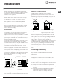
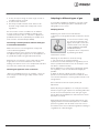
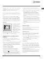
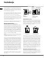
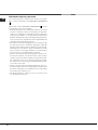
Room ventilation
The appliance may only be installed in permanently-
ventilated rooms, according to current national
legislation. The room in which the appliance is installed
must be ventilated adequately so as to provide as
much air as is needed by the normal gas combustion
process (the flow of air must not be lower than 2 m
3
/h
per kW of installed power).
The air inlets, protected by grilles, should have a duct
with an inner cross section of at least 100 cm
2
and
should be positioned so that they are not liable to even
partial obstruction (see gure A).
These inlets should be enlarged by 100% - with a
minimum of 200 cm
2
- whenever the surface of the
hob is not equipped with a flame failure safety device.
When the flow of air is provided in an indirect manner
from adjacent rooms (see gure B), provided that these
are not communal parts of a building, areas with
increased fire hazards or bedrooms, the inlets should
be fitted with a ventilation duct leading outside as
described above.
! After prolonged use of the appliance, it is advisable to
open a window or increase the speed of any fans used.
Disposing of combustion fumes
The disposal of combustion fumes should be
guaranteed using a hood connected to a safe and
efficient natural suction chimney, or using an electric
fan that begins to operate automatically every time the
appliance is switched on (see gure).
! The liquefied petroleum gases are heavier than air
and collect by the floor, therefore all rooms containing
LPG cylinders must have openings leading outside so
that any leaked gas can escape easily.
LPG cylinders, therefore, whether partially or
completely full, must not be installed or stored in rooms
or storage areas that are below ground level (cellars,
etc.). Only the cylinder being used should be stored
in the room; this should also be kept well away from
sources of heat (ovens, chimneys, stoves) that may
cause the temperature of the cylinder to rise above
50°C.
Positioning and levelling
! It is possible to install the appliance alongside
cupboards whose height does not exceed that of the
hob surface.
! Make sure that the wall in contact with the back of
the appliance is made from a non-flammable, heat-
resistant material (T 90°C).
To install the appliance correctly:
• Place it in the kitchen, dining room or the bed-sit (not
in the bathroom).
• If the top of the hob is higher than the cupboards,
the appliance must be installed at least 200 mm away
from them.
• If the cooker is installed underneath a wall cabinet,
there must be a minimum distance of 420 mm
between this cabinet and the top of the hob.
Installation
Adjacent room Room requiring
ventilation
A
B
Ventilation opening for
comburent air
Increase in the gap
between the door and
the flooring
A
Fumes channelled
straight outside
Fumes channelled through a
chimney or a branched flue
system (reserved for cooking
appliances)

4
GB
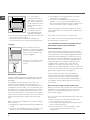
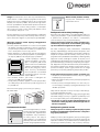
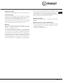
• If the cooker is
installed underneath a
wall cabinet, there must
be a minimum distance
of 420 mm between this
cabinet and the top of
the hob.
This distance should be
increased to 700 mm
if the wall cabinets are
flammable (see gure).
• Do not position blinds behind the cooker or less than
200 mm away from its sides.
• Any hoods must be installed according to the
instructions listed in the relevant operating manual.
Levelling
If it is necessary to level the
appliance, screw the adjustable
feet into the places provided on
each corner of the base of the
cooker (see gure).
The legs* fit into the slots on the
underside of the base of the
cooker.
Electrical connection
Install a standardised plug corresponding to the load
indicated on the appliance data plate (see Technical
data table).
The appliance must be directly connected to the
mains using an omnipolar circuit-breaker with a
minimum contact opening of 3 mm installed between
the appliance and the mains. The circuit-breaker must
be suitable for the charge indicated and must comply
with NFC 15-100 regulations (the earthing wire must
not be interrupted by the circuit-breaker). The supply
cable must be positioned so that it does not come into
contact with temperatures higher than 50°C at any
point.
Before connecting the appliance to the power supply,
make sure that:
• The appliance is earthed and the plug is compliant with
the law.
• The socket can withstand the maximum power of the
appliance, which is indicated by the data plate.
HOOD
420
Min.
min.
650
mm. with hood
min.
700
mm. without hood
mm.
600
Min. mm.
420
Min. mm.
• The voltage is in the range between the values
indicated on the data plate.
• The socket is compatible with the plug of the
appliance. If the socket is incompatible with the
plug, ask an authorised technician to replace it. Do
not use extension cords or multiple sockets.
! Once the appliance has been installed, the power
supply cable and the electrical socket must be easily
accessible.
! The cable must not be bent or compressed.
! The cable must be checked regularly and replaced
by authorised technicians only.
! The manufacturer declines any liability should
these safety measures not be observed.
Gas connection
Connection to the gas network or to the gas cylinder
may be carried out using a flexible rubber or steel hose,
in accordance with current national legislation and after
making sure that the appliance is suited to the type of
gas with which it will be supplied (see the rating sticker
on the cover: if this is not the case see below). When
using liquid gas from a cylinder, install a pressure
regulator which complies with current national
regulations. To make connection easier, the gas
supply may be turned sideways*: reverse the position
of the hose holder with that of the cap and replace the
gasket that is supplied with the appliance.
! Check that the pressure of the gas supply is
consistent with the values indicated in the Table
of burner and nozzle specifications (see below).
This will ensure the safe operation and durability of
your appliance while maintaining efficient energy
consumption.
Gas connection using a flexible rubber hose
Make sure that the hose complies with current national
legislation. The internal diameter of the hose must
measure: 8 mm for liquid gas supply; 13 mm for
methane gas supply.
Once the connection has been performed, make sure
that the hose:
• Does not come into contact with any parts that
reach temperatures of over 50°C.
• Is not subject to any pulling or twisting forces and
that it is not kinked or bent.
• Does not come into contact with blades, sharp
corners or moving parts and that it is not
compressed.

GB
5
• Is easy to inspect along its whole length so that its
condition may be checked.
• Is shorter than 1500 mm.
• Fits firmly into place at both ends, where it will
be fixed using clamps that comply with current
regulations.
! If one or more of these conditions is not fulfilled
or if the cooker must be installed according to the
conditions listed for class 2 - subclass 1 appliances
(installed between two cupboards), the flexible steel
hose must be used instead (see below).
Connecting a flexible jointless stainless steel pipe
to a threaded attachment
Make sure that the hose and gaskets comply with
current national legislation.
To begin using the hose, remove the hose holder on
the appliance (the gas supply inlet on the appliance is
a cylindrical threaded 1/2 gas male attachment).
! Perform the connection in such a way that the hose
length does not exceed a maximum of 2 metres,
making sure that the hose is not compressed and does
not come into contact with moving parts.
Checking the tightness of the connection
When the installation process is complete, check the
hose fittings for leaks using a soapy solution. Never
use a flame.
Adapting to different types of gas
It is possible to adapt the appliance to a type of gas
other than the default type (this is indicated on the
rating label on the cover).
Adapting the hob
Replacing the nozzles for the hob burners:
1. Remove the hob grids and slide the burners off their
seats.
2. Unscrew the nozzles using
a 7 mm socket spanner (see
gure), and replace them with
nozzles suited to the new type
of gas (see Burner and nozzle
speci cations table).
3. Replace all the components
by following the above
instructions in reverse.
Adjusting the hob burners’ minimum setting:
1. Turn the tap to the minimum position.
2. Remove the knob and adjust the regulatory screw,
which is positioned inside or next to the tap pin, until
the flame is small but steady.
! If the appliance is connected to a liquid gas supply,
the regulatory screw must be fastened as tightly as
possible.
3. While the burner is alight, quickly change the
position of the knob from minimum to maximum and
vice versa several times, checking that the flame is not
extinguished.
! The hob burners do not require primary air
adjustment.
! After adjusting the appliance so it may be used with
a different type of gas, replace the old rating label with
a new one that corresponds to the new type of gas
(these labels are available from Authorised Technical
Assistance Centres).
! Should the gas pressure used be different (or vary
slightly) from the recommended pressure, a suitable
pressure regulator must be fitted to the inlet hose in
accordance with current national regulations relating to
“regulators for channelled gas”.

6
GB
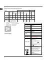
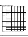
Table of burner and nozzle specifications
S
R
ø 145
ø 180
KN3N65SA/BG
At 15°C and 1013 mbar- dry gas
** Propane P.C.S. = 50,37 MJ/Kg
*** Butane P.C.S. = 49,47 MJ/Kg
Natural P.C.S. = 37,78 MJ/m
3
Table 1 Liquid Gas Natural Gas
Burner Diameter
(mm)
Thermal Power
kW (p.c.s.*)
By-Pass
1/100
Nozzle
1/100
Flow*
g/h
Nozzle
1/100
Flow*
l/h
Nominal Reduce-
d
(mm) (mm) *** ** (mm)
Fast
(Large)(R)
100 3.00 0.7 41 87 218 214 128 286
Semi Fast
(Medium)(S)
75 1.90 0.4 30 70 138 136 104 181
Supply
Pressures
Nominal (mbar)
Minimum (mbar)
Maximum (mbar)
28-30
20
35
37
25
45
20
17
25
TABLE OF CHARACTERISTSICS
Dimensions (with
drawn guide rails)
width 39 cm
height 34 cm
depth 41 cm
Volume (with
drawn guide rails)
54 l
Maximum absorber
power:
5600 W
Dimensions of the
lower compartment
width 42 cm
height 23 cm
depth 44 cm
Burners
may be adapted for use with any type
of gas shown on the data plate, which
is located inside the flap or, after the
oven compartment has been opened,
on the left-hand wall inside the oven.
Electric Plate
Rapid Ø 145 mm: 1500 W
Rapid Ø 180 mm: 2000 W
ENERGY LABEL
Directive 2002/40/EC on the label of
electric ovens.
Standard EN 50304
Energy consumption for Natural
convection – heating mode:
Convection;
Declared energy consumption for
Forced convection Class – heating
mode: Baking
This appliance conforms to the
following European Economic
Community directives: 2006/95/EC
dated 12/12/06 (Low Voltage) and
subsequent amendments -
2004/108/EC dated 15/12/04
(Electromagnetic Compatibility) and
subsequent amendments - 93/68/EEC
dated 22/07/93 and subsequent
amendments.
2002/96/EC
2009/142 of 30/11/09 (Gas)
1275/2008 (Stand-by/ Off mode)

GB
7
Start-up and use
Using the hob
Lighting the burners
For each BURNER knob there is a full ring showing the
strength of the flame for the relevant burner.
To light one of the burners on the hob:
1. Bring a flame or gas lighter close to the burner.
2. Press the BURNER knob and turn it in an
anticlockwise direction so that it is pointing to the
maximum flame setting .
3. Adjust the intensity of the flame to the desired level
by turning the BURNER knob in an anticlockwise
direction. This may be the minimum setting , the
maximum setting or any position in between the two.
If the appliance is fitted with an electronic lighting
device* (C), press the
BURNER knob and turn it in
an anticlockwise direction,
towards the minimum flame
setting, until the burner
is lit. The burner may be
extinguished when the knob
is released. If this occurs,
repeat the operation, holding the knob down for a longer
period of time.
f the appliance is equipped with a flame failure safety
device (X), press and hold the BURNER knob for
approximately 3-7 seconds to keep the flame alight
and to activate the device.
! If the flame is accidentally extinguished, switch off the
burner and wait for at least 1 minute before attempting
to relight it.
To switch the burner off, turn the knob until it reaches
the stop position •.
Electric hotplates
The corresponding knob may be turned clockwise
or anti-clockwise and set to any of the six different
positions:
When the selector knob is in any position other than the
off position, the ‘on’ light is illuminated.
Practical advice on using the burners
For the burners to work in the most efficient way
possible and to save on the amount of gas consumed,
it is recommended that only pans that have a lid and
a flat base are used. They should also be suited to the
size of the burner:
To identify the type of burner, please refer to the
diagrams contained in the “Burner and nozzle
specifications”.
Using the oven
! The first time you use your appliance, heat the empty
oven with its door closed at its maximum temperature
for at least half an hour. Ensure that the room is well
ventilated before switching the oven off and opening
the oven door. The appliance may emit a slightly
unpleasant odour caused by protective substances
used during the manufacturing process burning away.
! Before operating the product, remove all plastic film
from the sides of the appliance.
! Never put objects directly on the bottom of the oven;
this will avoid the enamel coating being damaged.
1. Select the desired cooking mode by turning the
SELECTOR knob.
2. Select the recommended temperature for the
cooking mode or the desired temperature by turning
the THERMOSTAT knob.
A list detailing cooking modes and suggested cooking
temperatures can be found in the relevant table (see
Oven cooking advice table).
During cooking it is always possible to:
• Change the cooking mode by turning the
SELECTOR knob.
• Change the temperature by turning the
THERMOSTAT knob.
• Stop cooking by turning the SELECTOR knob to the
“0” position.
! Always place cookware on the rack(s) provided.
THERMOSTAT indicator light
When this is illuminated, the oven is generating heat.
It switches off when the inside of the oven reaches
the selected temperature. At this point the light
illuminates and switches off alternately, indicating
that the thermostat is working and is maintaining the
temperature at a constant level.
X
C
Setting Normal or Fast Plate
0
Off
1
Low
2 - 5
Medium
6
High
Burner ř Cookware diameter (cm)
Fast (R) 24 - 26
Semi Fast (S) 16 - 20

8
GB
same. A maximum of 2 racks can be used at the same
time, following the instructions in the section entitled:
“Cooking On More Than One Rack”.
This fan assisted mode is particularly recommended
for dishes requiring a gratin finish or for those
requiring considerably prolonged cooking times,
such as for example: lasagne, pasta bakes, roast
chicken and potatoes, etc… Moreover, the excellent
heat distribution makes it possible to use lower
temperatures when cooking roasts. This results in
less loss of juices, meat which is more tender and a
decrease in the loss of weight for the roast. The fan
assisted mode is especially suited for cooking fish,
which can be prepared with the addition of a limited
amount of condiments, thus maintaining their flavour
and appearance.
Desserts: the fan assisted mode is also perfect for
baking leavened cakes.
Moreover, this mode can also be used to thaw quickly
white or red meat and bread by setting the temperature
to 80 °C. To thaw more delicate foods, set the
thermostat to 60°C or use only the cold air circulation
feature by setting the thermostat to 0°C.
TOP OVEN mode
Temperature: any temperature between 50°C and Max.
The top heating element comes on.
This mode can be used to brown food at the end of
cooking.
GRILL mode
Temperature: any temperature between 50°C and Max.
The top heating element and the turnspit come on.
The extremely high and direct temperature of the grill
makes it possible to brown the surface of meats and
roasts while locking in the juices to keep them tender.
The grill is also highly recommended for dishes that
require a high temperature on the surface: such as
beef steaks, veal, rib steak, filets, hamburgers etc...
Always leave the oven door ajar during cooking,
except when using the turnspit.
Some grilling examples are included in the “Practical
Cooking Advice” paragraph..
FAN ASSISTED GRILL mode
Temperature: any temperature between 50°C and 200°C.
The top central heating element and the fan come
on. This combination of features increases the
effectiveness of the unidirectional thermal radiation of
the heating elements through forced circulation of the
air throughout the oven. This helps prevent food from
burning on the surface, allowing the heat to penetrate
right into the food. Excellent results are achieved with
kebabs made with meats and vegetables, sausages,
Oven light
This is switched on by turning the SELECTOR knob to
any position other than “0”. It remains lit as long as the
oven is operating. By selecting
with the knob, the
light is switched on without any of the heating elements
being activated.
Cooking modes
BAKING mode
Temperature: any temperature between 50°C and Max.
The rear heating element and the fan come on,
guaranteeing delicate heat distributed uniformly
throughout the oven.
This mode is ideal for baking and cooking delicate
foods - especially cakes that need to rise - and for the
preparation of certain tartlets on 3 shelves at the same
time. Here are a few examples: cream puffs, sweet and
savoury biscuits, savoury puffs, Swiss rolls and small
portions of vegetables au gratin, etc…..
CONVECTION mode
Temperature: any temperature between 50°C and Max.
On this setting, the top and bottom heating elements
come on. This is the classic, traditional type of oven
which has been perfected, with exceptional heat
distribution and reduced energy consumption. The
convection oven is still unequalled when it comes to
cooking dishes made up of several ingredients, e.g.
cabbage with ribs, Spanish style cod, Ancona style
stockfish, tender veal strips with rice, etc. Excellent
results are achieved when preparing veal or beef-
based dishes as well (braised meats, stew, goulash,
wild game, ham etc.) which need to cook slowly and
require basting or the addition of liquid. It nonetheless
remains the best system for baking cakes as well as
fruit and cooking using covered casserole dishes
for oven baking. When cooking in convection mode,
only use one dripping pan or cooking rack at a time,
otherwise the heat distribution will be uneven. Using
the different rack heights available, you can balance
the amount of heat between the top and the bottom of
the oven. Select from among the various rack heights
based on whether the dish needs more or less heat
from the top.
FAN ASSISTED mode
Temperature: any temperature between 50°C and Max.
The heating elements, as well as the fan, will come
on. Since the heat remains constant and uniform
throughout the oven, the air cooks and browns food
uniformly over its entire surface. With this mode, you
can also cook various dishes at the same time, as
long as their respective cooking temperatures are the

GB
9
• Positions 2 and 4 are used and that food that
requires more heat is placed on the rack in position
2.
• When cooking foods that require different cooking
times and temperatures, set a temperature
that is halfway between the two recommended
temperatures (see Oven cooking advice table) and
place the more delicate food on the rack in position
4. Remove the food that requires a shorter cooking
time first.
• When cooking pizzas on several racks with the
temperature set to 220°C, the oven is preheated for
15 minutes. Generally speaking, cooking on the rack
in position 4 takes longer: we recommend that the
pizza cooked on the lowest rack position is removed
first, followed by the pizza cooked in position 4 a few
minutes later.
• Place the dripping pan on the bottom and the rack
on top.
Electronic timer
This function displays the time and works as a timer
which counts down to zero.
! All functions will be implemented approximately 7
seconds after they have been set.
Resetting the clock
After the appliance has been connected to the power
supply, or after a power cut, the clock display will
begin to blink, showing the figure: 0:00
• Press button
and then buttons - and + to set the
exact time. Press and hold the buttons to quicken
the count upwards.
Any necessary modifications can be made by
repeating the above process.
Timer feature
This function may be accessed by pressing the
button, after which the display will show the symbol
. Every time the + button is pressed it corresponds
to a time increase of 10 seconds, until it reaches 99
minutes and 50 seconds. After this point, each press of
the button represents an increase of one minute, up to a
maximum of 10 hours.
Pressing the - button reduces the time.
After the time period has been set, the timer will begin
to count down. When the timer reaches zero, the
buzzer will sound (this may be stopped by pressing
any button).
ribs, lamb chops, chicken in a spicy sauce, quail, pork
chops, etc.
This mode is also ideal for cooking fish steaks, like
swordfish, tuna, grouper, stuffed cuttlefish etc.
! The TOP OVEN, GRILL and FAN ASSISTED GRILL
cooking modes must be performed with the oven door
shut.
! When using the TOP OVEN and GRILL cooking
modes, place the rack in position 5 and the dripping
pan in position 1 to collect cooking residues (fat and/
or grease). When using the FAN ASSISTED GRILL
cooking mode, place the rack in position 2 or 3 and the
dripping pan in position 1 to collect cooking residues.
Rotisserie
To activate the rotisserie
function (see diagram)
proceed as follows:
1. Place the dripping pan
in position 1.
2. Place the rotisserie
support in position 4 and
insert the spit in the hole
provided on the back
panel of the oven.
3. Activate the rotisserie
by selecting
with the SELECTOR knob.
Practical advice on using the electric
hotplates
To avoid heat loss and damage to the hotplates use
pans with a flat base, whose diameter is no less than
that of the hotplate itself.
! Before using the hotplates for the first time, you should
heat them at maximum temperature for approximately
4 minutes, without placing any pans on them. During
this initial stage, their protective coating hardens and
reaches its maximum resistance.
Practical cooking advice
Cooking on several shelves simultaneously
If it is necessary to use two racks, use the FAN
ASSITED mode
, as this is the only cooking mode
suited to this type of cooking. We also recommend that:
• Positions 1 and 5 are not used. This is because
excessive direct heat can burn temperature sensitive
foods.

10
GB
The time may be displayed by pressing the button,
and the symbol indicates that the timer function has
been set. After approximately 7 seconds, the display will
automatically revert to the timer.
Cancelling a time that has already been set
Press the - button until the display shows 0:00.
Adjusting the buzzer volume
After selecting and confirming the clock settings, use
the - button to adjust the volume of the alarm buzzer.

GB
11
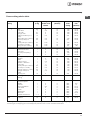
Oven cooking advice table
Selector knob
setting
Food to be cooked Weight
(in kg)
Cooking rack
position from
bottom
Preheating time
(minutes)
Thermostat
knob
setting
Cooking
time
(minutes)
Baking
Tarts
Fruit cakes
Plum cake
Sponge cake
Stuffed pancakes (on 2
racks)
Small cakes (on 2 racks)
Cheese puffs (on 2
racks)
Cream puffs (on 3 racks)
Biscuits (on 3 racks)
Meringues (on 3 racks)
0.5
1
0.7
0.5
1.2
0.6
0.4
0.7
0.7
0.5
3
2/3
3
3
2-4
2-4
2-4
1-3-5
1-3-5
1-3-5
15
15
15
15
15
15
15
15
15
15
180
180
180
160
200
190
210
180
180
90
20-30
40-45
40-50
25-30
30-35
20-25
15-20
20-25
20-25
180
Convection
Duck
Roast veal or beef
Pork roast
Biscuits (short pastry)
Tarts
1
1
1
-
1
3
3
3
3
3
15
15
15
15
15
200
200
200
180
180
65-75
70-75
70-80
15-20
30-35
Fan assisted
Pizza (on 2 racks)
Lasagne
Lamb
Roast chicken +
potatoes Mackerel
Plum-cake
Cream puffs (on 2 racks)
Biscuits (on 2 racks)
Sponge cake (on 1 rack)
Sponge cake (on 2
racks)
Savoury pies
1
1
1
1
1
1
0.5
0.5
0.5
1.0
1.5
2-4
3
2
2-4
2
2
2-4
2-4
2
2-4
3
15
10
10
10
10
10
10
10
10
10
15
220
200
180
180
180
170
190
180
170
170
200
15-20
30-35
50-60
60-75
30-35
40-50
20-25
10-15
15-20
20-25
25-30
Top Oven
Browning food to perfect
cooking
- 3/4 15 220 -
Grill
Soles and cuttlefish
Squid and prawn
kebabs
Cod filet
Grilled vegetables
Veal steak
Cutlets
Hamburgers
Mackerels
Toasted sandwiches
1
1
1
1
1
1
1
1
n.° 4
4
4
4
3/4
4
4
4
4
4
5
5
5
5
5
5
5
5
5
Max
Max
Max
Max
Max
Max
Max
Max
Max
8-10
6-8
10
10-15
15-20
15-20
7-10
15-20
2-3
Fan assisted
grill
Grilled chicken
Cuttlefish
1.5
1.5
3
3
5
5
200
200
55-60
30-35
!
cooking times are approximate and may vary according to personal taste. When cooking using the grill or fan
assisted grill, the dripping pan must always be placed on the 1st oven rack from the bottom.

12
GB
Precautions and tips
! This appliance has been designed and manufactured
in compliance with international safety standards.
The following warnings are provided for safety reasons
and must be read carefully.
General safety
• The appliance was designed for domestic use inside
the home and is not intended for commercial or
industrial use.
• The appliance must not be installed outdoors, even in
covered areas. It is extremely dangerous to leave the
appliance exposed to rain and storms.
• Do not touch the appliance with bare feet or with wet
or damp hands and feet.
• The appliance must be used by adults only for
the preparation of food, in accordance with the
instructions provided in this booklet.
• The instruction booklet accompanies a class 1
(insulated) or class 2 - subclass 1 (recessed
between 2 cupboards) appliance.
• Keep children away from the oven.
• Make sure that the power supply cables of other
electrical appliances do not come into contact with
the hot parts of the oven.
• The openings used for the ventilation and dispersion
of heat must never be covered.
• Always use oven gloves when placing cookware in
the oven or when removing it.
• Do not use flammable liquids (alcohol, petrol, etc...)
near the appliance while it is in use.
• Do not place flammable material in the lower storage
compartment or in the oven itself. If the appliance is
switched on accidentally, it could catch fire.
• Always make sure the knobs are in the “
•” position
when the appliance is not in use.
• When unplugging the appliance, always pull the plug
from the mains socket; do not pull on the cable.
• Never perform any cleaning or maintenance work
without having disconnected the appliance from the
electricity mains.
• If the appliance breaks down, under no
circumstances should you attempt to repair
the appliance yourself. Repairs carried out by
inexperienced persons may cause injury or further
malfunctioning of the appliance. Contact Assistance.
• Do not rest heavy objects on the open oven door.
•
The appliance should not be operated by people
(including children) with reduced physical, sensory
or mental capacities, by inexperienced individuals
or by anyone who is not familiar with the product.
These individuals should, at the very least, be
supervised by someone who assumes responsibility
for their safety or receive preliminary instructions
relating to the operation of the appliance.
WARNING! The glass lid can break in if it is heated up.
Turn off all the burners and the electric plates before clos-
ing the lid
.
Disposal
• When disposing of packaging material: observe
local legislation so that the packaging may be
reused.
• The European Directive 2002/96/EC relating
to Waste Electrical and Electronic Equipment
(WEEE) states that household appliances should
not be disposed of using the normal solid urban
waste cycle. Exhausted appliances should be
collected separately in order to optimise the cost
of re-using and recycling the materials inside the
machine, while preventing potential damage to the
atmosphere and to public health. The crossed-out
dustbin is marked on all products to remind the
owner of their obligations regarding separated
waste collection. For more information relating to the
correct disposal of household appliances, owners
should contact their local authorities or appliance
dealer.
Respecting and conserving the
environment
• You can help to reduce the peak load of the
electricity supply network companies by using the
oven in the hours between late afternoon and the
early hours of the morning.
• Always keep the oven door closed when using the
GRILL and FAN-ASSISTED GRILL mode cooking.
This will achieve better results while saving energy
(approximately 10%).
• Check the door seals regularly and wipe them clean
to ensure they are free of debris so that they adhere
properly to the door, thus avoiding heat dispersion.

GB
13
Switching the appliance off
Disconnect your appliance from the electricity supply
before carrying out any work on it.
Cleaning the appliance
! Never use steam cleaners or pressure cleaners on
the appliance.
• The stainless steel or enamel-coated external parts
and the rubber seals may be cleaned using a
sponge that has been soaked in lukewarm water
and neutral soap. Use specialised products for the
removal of stubborn stains. After cleaning, rinse well
and dry thoroughly. Do not use abrasive powders or
corrosive substances.
• The hob grids, burner caps, flame spreader rings
and burners may be removed to make cleaning
easier; wash them in hot water and non-abrasive
detergent, making sure all burnt-on residue is
removed before drying them thoroughly.
• For hobs with electronic ignition, the terminal part of
the electronic lighting devices should be cleaned
frequently and the gas outlet holes should be
checked for blockages.
• The inside of the oven should ideally be cleaned
after each use, while it is still lukewarm. Use hot
water and detergent, then rinse well and dry with a
soft cloth. Do not use abrasive products.
•
Clean the glass part of the oven door using a
sponge and a non-abrasive cleaning product, then
dry thoroughly with a soft cloth. Do not use rough
abrasive material or sharp metal scrapers as these
could scratch the surface and cause the glass to
crack.
• The accessories can be washed like everyday
crockery, and are even dishwasher safe.
TOpen the cover fully and pull it upwards (see figure).
! Do not close the cover when the burners are alight or
when they are still hot.
! Remove any liquid from the lid before opening it.
Inspecting the oven seals
Check the door seals around the oven regularly. If
the seals are damaged, please contact your nearest
Authorised After-sales Service Centre. We recommend
that the oven is not used until the seals have been
replaced.
Replacing the oven light bulb
1. After disconnecting the oven from the electricity
mains, remove the glass lid covering the lamp socket
(see gure).
2. Remove the light bulb and replace it with a similar
one: voltage 230 V, wattage 25 W, cap E 14.
3. Replace the lid and reconnect the oven to the
electricity supply.
Gas tap maintenance
Over time, the taps may become
jammed or difficult to turn. If this
occurs, the tap must be replaced.
! This procedure must be
performed by a qualified
technician who has been
authorised by the manufacturer.
Assistance
Please have the following information to hand:
• The appliance model (Mod.).
• The serial number (S/N).
This information can be found on the data plate located
on the appliance and/or on the packaging.
Care and maintenance
WARNING! The glass lid can break in if it
is heated up. Turn off all the burners and
the electric plates before closing the lid
.
The cover
If the cooker is fitted with
a glass cover, this cover
should be cleaned
using lukewarm water.
Do not use abrasive
products.
It is possible to remove
the cover in order to
make cleaning the area
behind the hob easier.

Instalacja
! Przed przystàpieniem do u˝ytkowania urzàdzenia, nale˝y
starannie zapoznaç si´ z podr´cznikiem u˝ytkownika. Za-
wiera on wa˝ne zalecenia dotyczàce bezpieczeƒstwa insta-
lacji, obs∏ugi oraz konserwacji kuchenki. Podr´cznik nale˝y
zachowaç do póêniejszego u˝ytku.
! Instrukcj´ nale˝y zachowaç na przysz∏oÊç. Instrukcja mu-
si byç do∏àczona do urzàdzenia w przypadku sprzeda˝y,
przekazywania innym osobom lub przeprowadzki.
! Poni˝sze instrukcje przeznaczone sà dla wykwalifikowane-
go specjalisty instalujàcego urzàdzenie. Instrukcje te majà
na celu zapewnienie mo˝liwie najbardziej profesjonalnego
i doÊwiadczonego wykonania czynnoÊci zwiàzanych z in-
stalacjà i konserwacjà urzàdzenia.
! Wszelkie prace regulacyjne lub konserwacyjne nale˝y
przeprowadzaç po od∏àczeniu kuchenki od zasilania.
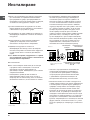
Wentylacja pomieszczenia
Wymagania dla pomieszczeƒ kuchennych
Przed przystàpieniem do instalowania kuchni gazowej
w pomieszczeniu kuchennym itp., nale˝y upewniç si´, czy
spe∏nia ono stawiane mu wymagania. Podstawa prawna,
w oparciu, o którà oceniamy przydatnoÊç pomieszczenia
do zainstalowania w nim kuchni gazowej, jest Rozporzà-
dzenie Ministra Gospodarki Przestrzennej i Budownictwa
z dnia 14 grudnia 1994 r. w sprawie warunków technicz-
nych, jakim powinny odpowiadaç budynki i ich usytuowa-
nie, b´dàce aktem wykonawczym do Prawa budowlanego
(Dz.U. nr 75 z dnia 16-12-2002 poz. 690).
Wa˝ne: niniejsze urzàdzenie mo˝e byç instalowane i wyko-
rzystywane wy∏àcznie w pomieszczeniach z trwa∏à wentyla-
cjà, zgodnie z obowiàzujàcymi przepisami
Pomieszczenie powinno umo˝liwiaç dop∏yw powietrza, któ-
re niezb´dne jest do w∏aÊciwego spalania gazu. Dop∏yw po-
wietrza powinien byç nie mniejszy ni˝ 2 m
3
/h na jeden kW
mocy palników. Powietrze mo˝e byç dostarczane w wyniku
bezpoÊredniego przep∏ywu z zewnàtrz przez kana∏ o prze-
kroju, co najmniej 100 cm
2
, którego konstrukcja musi unie-
mo˝liwiaç przypadkowe zablokowanie (Rysunek A). Otwór
ten nale˝y powi´kszyç o 100%, je˝eli instalacja kominowa
nie zosta∏a wyposa˝ona w urzàdzenie bezpieczeƒstwa, wy-
krywajàce ogieƒ. Ewentualnie dop∏yw powietrza mo˝e odby-
waç si´ poÊrednio z sàsiednich pomieszczeƒ, które wypo-
sa˝one sà w kana∏y wentylacyjne wychodzàce na zewnàtrz,
spe∏niajàce wymagania dla kana∏ów opisane powy˝ej.
Wszystko to przy za∏o˝eniu, ˝e sàsiednie pomieszczenia nie
sà pomieszczeniami wspólnymi, sypialniami ani nie wyst´-
puje w nich zagro˝enie po˝arowe (Rysunek B).
! JeÊli kuchnia jest wykorzystywana intensywnie I d∏ugo, to
mo˝e okazaç si´ konieczne otworzenie okna dla poprawie-
nia wentylacji.
Odprowadzanie spalin
Pomieszczenie, w którym ma byç zainstalowana kuchnia
powinno byç wyposa˝one w system wentylacji odprowa-
dzajàcy na zewnàtrz spaliny powstajàce podczas spalania.
Instalacja ta powinna sk∏adaç si´ z okapu lub wentylatora
elektrycznego, który w∏àcza si´ automatycznie za ka˝dym
razem, gdy uruchamiana jest kuchnia.
! Gaz p∏ynny jest ci´˝szy od powietrza i w zwiàzku z tym ma
tendencje do gromadzenia si´ na dolnych poziomach. Po-
koje, w których zainstalowano butle z gazem p∏ynnym, po-
winny byç wyposa˝one w kana∏y wentylacyjne wyprowa-
dzone z pomieszczenia na zewnàtrz, umo˝liwiajàce wydo-
stawanie si´ gazu w przypadku nieszczelnoÊci. Z tego sa-
mego powodu butle z gazem, zarówno puste jak i cz´Êcio-
wo nape∏nione, nie powinny byç ani instalowane, ani prze-
chowywane w pomieszczeniach usytuowanych pod po-
wierzchnià ziemi (piwnice, itp.). Dobrà praktykà jest prze-
chowywanie w pomieszczeniu kuchennym jedynie tego
zbiornika, który jest aktualnie wykorzystywany, pod warun-
kiem, ˝e nie znajduje si´ on zbyt blisko êróde∏ ciep∏a (piecy-
ki, kominki, piekarniki, itp.), które mog∏yby zwi´kszyç tem-
peratur´ we wn´trzu zbiornika powy˝ej 50°C.
Ustawianie i poziomowanie kuchni
Kuchnia gazowa pod wzgl´dem ochrony przed przegrza-
niem otaczajàcych powierzchni jest przyrzàdem klasy X i ja-
ko taka mo˝e byç zabudowana w ciàgu meblowym tylko do
wysokoÊci p∏yty roboczej tj. 850 mm od posadzki. Zabudo-
wa powy˝ej tego poziomu jest zabroniona.
A
Rysunek A
Przyk∏ady otworów
wentylacyjnych
pomieszczenie
sàsiednie
pomieszczenie, które
ma byç wentylowane
Rysunek B
Powi´kszenie szczeliny
wentylacyjnej pomi´dzy
oknem i pod∏ogà
komin lub rozga∏´ziony
kana∏ dymowy
bezpoÊrednio na zewnàtrz
(w przypadku kuchenek)
PL
14

15
PL
Uwaga: Kuchnia w klasie X nie mo˝e byç zabudowana wy-
sokim meblem. Jednak w ka˝dym przypadku meble do za-
budowy muszà mieç ok∏adzin´ oraz klej do jej przyklejenia
odporny na temperatur´ 100°C. Niespe∏nienie tego warun-
ku mo˝e spowodowaç zdeformowanie powierzchni lub od-
klejenia ok∏adziny. Je˝eli nie mamy pewnoÊci, co do odpor-
noÊci termicznej mebli, kuchni´ nale˝y zabudowaç mebla-
mi zachowujàc odst´p ok. 2 cm.
! Âciana znajdujàca si´ za kuchnià powinna byç uodpornio-
na na wysokie temperatury. Podczas korzystania z kuchni, jej
tylna Êciana mo˝e rozgrzaç si´ do temperatury oko∏o 90°C.
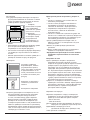
W∏aÊciwa instalacja kuchni wymaga uwzgl´dnienia
poni˝szych kwestii:
• Kuchni´ mo˝na zainstalowaç w kuchni, kuchnio-jadalni
lub pokoju spe∏niajàcym warunki techniczne wynikajàce
z przytoczonych przepisów; nie wolno jej instalowaç w ∏a-
zience ani w pomieszczeniu z prysznicem.
• Meble znajdujàce si´ obok kuchni, które wystajà powy˝ej
powierzchni kuchni, powinny znajdowaç si´ w odleg∏oÊci,
co najmniej 200 mm od kraw´dzi p∏yty z palnikami.
• Szafki sàsiadujàce z okapem
powinny znajdowaç si´ w odle-
g∏oÊci, co najmniej 420 mm od
powierzchni kuchni. Minimalna
odleg∏oÊç nad poziomem palni-
ków, w jakiej mogà byç moco-
wane elementy umeblowania
kuchni wykonane z materia∏ów
niezabezpieczonych termicznie
wynosi 700 mm.
• Nie stosowaç zas∏on z ty∏u kuchni i w odleg∏oÊci nie
mniejszej ni˝ 200 mm od jej boków.
• Okapy nale˝y montowaç zgodnie z instrukcjami podany-
mi w do∏àczonych do nich instrukcjach obs∏ugi, ale nie ni-
˝ej ni˝ 650 mm.
Kuchnia ma nast´pujàcà technicznà specyfikacj´:
Kat. II2ELs3B/P
Poziomowanie kuchni
Kuchenka wyposa˝ona jest w nó˝-
ki o zmiennej wysokoÊci umo˝liwia-
jàce odpowiednie wypoziomowa-
nie urzàdzania. JeÊli jest to koniecz-
ne nale˝y wkr´ciç lub wykr´ciç
nó˝ki znajdujàce si´ w naro˝nikach
podstawy kuchenki a˝ do uzyska-
nia w∏aÊciwego wypoziomowania.
Monta˝ nó˝ek (niektóre modele)
Przyrzàd do montowania nó˝ek
w podstawie kuchni
Pod∏àczenie do instalacji elektrycznej
Kuchenki, które wyposa˝one sà w trójbiegunowy kabel za-
silajàcy przystosowane sà do zasilania pràdem zmiennym
o parametrach podanych na tabliczce znamionowej
(umieszczonej we wn´ce pod piekarnikiem).
Uwaga: Do zasilania kuchni nie nale˝y stosowaç trans-
formatorów, przejÊciówek ani boczników, gdy˝ mogà
si´ one nadmiernie nagrzewaç lub zapaliç.
Na kablu zasilajàcym nale˝y zamontowaç standardowà
wtyczk´, odpowiadajàcà maksymalnemu obcià˝eniu, które
podano na tabliczce znamionowej. Ewentualnie, pod∏àczyç
urzàdzenie bezpoÊrednio do instalacji elektrycznej. W tym
przypadku nale˝y dodatkowo zamontowaç jednobiegunowy
wy∏àcznik sieciowy o odleg∏oÊci styków, co najmniej 3 mm
i odpowiadajàcy obowiàzujàcym przepisom bezpieczeƒstwa
(przewód uziemiajàcy nie mo˝e byç roz∏àczany przez wy∏àcz-
nik). Wy∏àcznik ten b´dzie odcina∏ kuchenk´ od zasilania. Ka-
bel zasilajàcy powinien byç u∏o˝ony w taki sposób, aby tem-
peratura w ˝adnym punkcie jego powierzchni nie mog∏a
przekroczyç temperatury pokojowej powi´kszonej o 50°C.
Przed wykonaniem po∏àczenia nale˝y sprawdziç czy:
• Urzàdzenie posiada obwód ochronny i wtyczk´ zgodnà
z obowiàzujàcymi przepisami.
• Bezpiecznik oraz instalacja elektryczna wytrzymajà obcià-
˝enie kuchenki.
• Instalacja elektryczna wyposa˝ona jest w skuteczny sys-
tem uziemiajàcy spe∏niajàcy wymagania aktualnych stan-
dardów i przepisów.
! Wtyczka lub wy∏àcznik sieciowy muszà byç ∏atwo dost´p-
ne po zainstalowaniu kuchenki.
! Przewód zasilajàcy nie mo˝e byç zagi´ty lub przygnieciony.
! Przewód zasilajàcy musi byç regularnie sprawdzany i w ra-
zie usterki wymieniony przez autoryzowanego technika.
! Producent nie ponosi ˝adnej odpowiedzialnoÊci za
ewentualne szkody wynik∏e z niew∏aÊciwego zainsta-
lowania urzàdzenia.
Pod∏àczenie gazu do kuchni
Uwaga: CzynnoÊç ta mo˝e byç wykonana jedynie przez
technika z odpowiednimi uprawnieniami, autoryzowa-
nego przez producenta.
Pod∏àczyç kuchni´ do butli gazowej lub rury instalacji gazo-
wej, przestrzegajàc obowiàzujàcych przepisów, wy∏àcznie po
uprzednim ustaleniu, czy kuchnia mo˝e byç zasilana gazem
wyst´pujàcym w danej instalacji. JeÊli jest inaczej, nale˝y wy-
HOOD
420
Min.
min.
650
mm. with hood
min.
700
mm. without hood
mm.
600
Min. mm.
420
Min. mm.
Klasa 2 podklasa 1
Klasa 1

konaç zalecania podane w cz´Êci „Dostosowywanie kuchen-
ki do ró˝nych rodzajów gazów”. Niektóre modele kuchenki
umo˝liwiajà pod∏àczenie instalacji gazowej z lewej lub prawej
strony kuchenki – aby zmieniç stron´ zasilania nale˝y zamie-
niç po∏o˝enie uchwytu w´˝a i korka zamykajàcego oraz wy-
mieniç uszczelk´ (do∏àczonà do kuchni). W przypadku pod-
∏àczenia do butli z gazem p∏ynnym nale˝y zastosowaç regu-
lator ciÊnienia, spe∏niajàcy obowiàzujàce przepisy.
Wa˝ne: nale˝y sprawdziç czy ciÊnienie gazu w instalacji
zgodne jest z zaleceniami podanymi w tabeli 1 zatytu∏owa-
nej „Parametry dysz i palników”. Zapewni to bezpiecznà
prac´ kuchni, w∏aÊciwe zu˝ycie gazu oraz przed∏u˝y czas
bezawaryjnej pracy kuchni.
Pod∏àczenie do sztywnej instalacji rurowej
(miedzianej lub stalowej)
Pod∏àczenie do instalacji gazowej powinno byç wykonane
w taki sposób, który nie wywo∏uje napr´˝eƒ w ˝adnym
punkcie instalacji ani na ˝adnej cz´Êci urzàdzenia.
Urzàdzenie wyposa˝one jest w regulowanà z∏àczk´
w kszta∏cie litery “L” oraz uszczelk´, które umo˝liwiajà pod-
∏àczenie do instalacji gazowej. Je˝eli zajdzie potrzeba prze-
kr´cenia z∏àczki to wymagana b´dzie równie˝ wymiana
uszczelki (do∏àczonej do urzàdzenia).
Z∏àcze doprowadzajàce gaz do kuchenki to m´ski cylinder
z gwintem 1/2.
Pod∏àczenie do elastycznego przewodu metalowego
Z∏àcze doprowadzajàce gaz do kuchenki to z∏àcze m´skie
z gwintem 1/2 do rur gazowych o przekroju okràg∏ym. Do
pod∏àczenia nale˝y stosowaç wy∏àcznie rury i uszczelki od-
powiadajàce aktualnie obowiàzujàcym normom. Maksy-
malna d∏ugoÊç przewodu elastycznego nie mo˝e przekra-
czaç 2000 mm. Po wykonaniu po∏àczenia nale˝y sprawdziç
czy elastyczny przewód metalowy nie styka si´ z ˝adnymi
cz´Êciami ruchomymi ani czy nie jest niczym przyciÊni´ty.
Pod∏àczenie w´˝em elastycznym
Kuchni´ gazowà pod∏àczamy w´˝em elastycznym tylko
w przypadku zasilania gazem p∏ynnym z butli gazowej.
Do pod∏àczenia nale˝y zastosowaç wà˝ gazowy odpowia-
dajàcy wymaganiom okreÊlonym przez krajowe normy. Je-
Êli kuchenka zasilana jest gazem p∏ynnym nale˝y zastoso-
waç regulatory ciÊnienia, które spe∏niajà krajowe przepisy
techniczne. Wewn´trzna Êrednica w´˝a powinna wynosiç:
• 8 mm, w przypadku zasilania gazem p∏ynnym
Sprawdziç czy wà˝ jest ÊciÊle dopasowany na obu koƒcach.
Do zamocowania w´˝a u˝yç standardowych zacisków,
G∏ównymi postanowienia obowiàzujàcych norm technicz-
nych przewidujà, ˝e:
• wà˝ nie powinien w ˝adnym punkcie stykaç si´ z „goràcy-
mi” elementami kuchenki;
• wà˝ nie powinien byç d∏u˝szy ni˝ 1,5 metra
• wà˝ nie powinien byç w ˝adnym miejscu zgi´ty ani nacià-
gni´ty, na ca∏ej swojej d∏ugoÊci nie powinien równie˝ po-
siadaç ciasnych zakr´tów ani zw´˝eƒ
• na ca∏ej swojej d∏ugoÊci wà˝ powinien byç dost´pny, tak,
aby mo˝liwa by∏a kontrola jego zu˝ycia
• w przypadku wykrycia nieszczelnoÊci wà˝ powinien byç
ca∏kowicie wymieniony; naprawianie nieszczelnego w´˝a
jest zabronione
Sprawdzanie szczelnoÊci
Wa˝ne: Po zakoƒczeniu instalacji kuchenki nale˝y spraw-
dziç szczelnoÊç wszystkich po∏àczeƒ stosujàc do tego wo-
d´ z myd∏em. Do sprawdzania szczelnoÊci nie wolno w ˝ad-
nym wypadku stosowaç ognia!
Dostosowywanie kuchenki
do ró˝nych rodzajów gazów
Aby dostosowaç kuchenk´ do gazu innego rodzaju, ni˝ ro-
dzaj, dla którego zaprojektowano kuchenk´ (patrz naklejka
na spodzie kuchenki lub na opakowaniu), nale˝y wymieniç
dysze palników, zgodnie z poni˝szà procedurà:
1. Zdemontowaç krat´ podpierajàcà garnki i wysunàç pal-
niki z kuchenki
2. Za pomocà klucza nasadowego
7mm odkr´ciç dysze i wymieniç je
na nowe dysze, odpowiednie do
gazu danego typu (patrz Tabela 1,
„Parametry dysz i palników”).
3. Ponownie zmontowaç razem cz´-
Êci, wykonujàc wy˝ej opisane
czynnoÊci w odwrotnej kolejnoÊci
Regulacja dop∏ywu powietrza do palnika
Palniki nie wymagajà takiej regulacji.
Regulacja minimalnej wielkoÊci p∏omienia
1. Ustawiç zawór gazu w po∏o˝eniu najmniejszego p∏omienia
2. Zdemontowaç pokr´t∏o i przekr´ciç Êrub´ regulacyjnà
(znajdujàcà si´ bàdê po jednej ze stron trzonka lub w je-
go Êrodku). Przekr´ciç Êrub´ w kierunku zgodnym z ru-
chem wskazówek zegara do po∏o˝enia, w którym p∏o-
mieƒ b´dzie ma∏y i stabilny.
3. Sprawdziç czy p∏omieƒ nie gaÊnie podczas szybkiego
kr´cenia zaworem
4. W przypadku niew∏aÊciwego dzia∏ania kuchenek wypo-
sa˝onych w urzàdzenie zabezpieczajàce (termoelement)
przy ustawieniu najmniejszego p∏omienia, nale˝y zwi´kszyç
wielkoÊç p∏omienia za pomocà Êruby.
!
W przypadku zasilania gazem p∏ynnym, Êruba regulacyj-
na powinna byç ca∏kowicie wkr´cona do samego koƒca.
!
Po zakoƒczonej regulacji, nale˝y zmieniç nalepk´ z opi-
sem rodzaju gazu, do jakiego kuchnia jest przystosowana.
!
JeÊli ciÊnienie gazu w instalacji ró˝ni si´ od wartoÊci, po-
danych w niniejszej instrukcji, nale˝y zastosowaç regulator
ciÊnienia.
PL
16

17
PL
Drying:
DANE TECHNICZNE
Mogà byç dostosowane do ró˝nych
rodzajów gazu, zgodnie z informacjà
przedstawionà na tabliczce znamionowej,
znajdujàcej si´ na:
– wewn´trznej stronie drzwiczek schowka;
– wewn´trznej stronie lewego boku kuchni
widoczna po wysuni´ciu szuflady.
Zobacz tabliczk´ znamionowà
Etykieta energetyczna jest zgodna
z Dyrektywà UE 2002/40/CE (norma EN
50304).
Energoch∏onnoÊç podana w oparciu
o nastawy piekarnika:
– pieczenie statyczne:
wybrana funkcja Tryb konwencjonalny
Deklarowana klasa energoch∏onnoÊci
podana dla trybu dynamicznego
– pieczenie dynamiczne:
wybrana funkcja „Pieczenie ciast”
szerokoÊç 44 cm
wysokoÊç 34 cm
g∏´bokoÊç 38 cm
szerokoÊç 42 cm
wysokoÊç 23 cm
g∏´bokoÊç 44 cm
54 litry
Palniki
Napi´cie
i cz´stotliwoÊç
zasilania
Etykieta
energetyczna
Wymiary
piekarnika
PojemnoÊç
piekarnika
Szuflada/
schowek kuchni
Dyrektywy unijne: 2006/95/EC z
dnia 12/12/06 (niskie napiêcie) z
póniejszymi zmianami
z dnia 15/12/04 (zgodnoæ
elektromagnetyczna) z
póniejszymi zmianami -
93/68/EEC z dnia 22/07/93 z
póniejszymi zmianami,
2009/142/EC z dnia 30/11/09 (gaz)
z póniejszymi zmianami, -
93/68/EEC z dnia 22/07/93 z
póniejszymi zmianami, -
2002/96/EC.
* przy gazie suchym 15°C 1013 mbar
G20 (GZ 50) p.c.i. 37,78 Mj/m
3
GZ350 (GZ35) p.c.i. 27,20 Mj/m
3
G30 (GPB) p.c.i. 49,47 MJ/kg
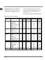
Palnik
Szybki (du˝y – R)
Âredniej pr´dkoÊci (Êredni – S)
CiÊnienie gazu
Ârednica
(mm)
Moc
termiczna
(p.c.i*)
Min.
Moc
termiczna
(p.c.i*)
Nominalna
Moc
termiczna
(p.c.i*)
Nominalna
Dysza
1/100
(mm)
Przep∏yw*
l/h
G20 (GZ50) G2.350 (GZ350)
Dysza
1/100
(mm)
Przep∏yw*
l/h
Dysza
1/100
(mm)
Przep∏yw*
g/h
1000,70128 2861583973,4087247
750,401041811432512,2070160
Minimalne
Nominalne (mbar)
Maksymalne
16
20
25
10
13
16
29
37
44
3,00
1,90
Gaz naturalny
G30 (GPB)
Gaz p∏ynny
Parametry dysz i palników
DANE TECHNICZNE
1275/2008 (Stand-by/ Off mode)
UWAGA! Szklana pokrywa może
popękać jeżeli zostanie nagrzana.
Należy wyłączyć wszystkie palniki
przed zamknięciem pokrywy. *Dotyczy
tylko modeli ze szklana pokrywa.
KN3N65SA/BG

18
PL
Uruchomienie
i obs∏uga kuchni
Pokr´t∏a oznaczone sà symbolami okreÊlajàcymi przypo-
rzàdkowanie palników gazowych lub p∏ytek elektrycznych
(o ile urzàdzenie jest w nie wyposa˝one).
Palnik gazowe
Palniki te ró˝nià si´ pod wzgl´dem wymiarów i mocy. Do
przygotowywania posi∏ku nale˝y u˝yç palnika o wymiarze
najbardziej zbli˝onym do rozmiarów stosowanego garnka.
Aby w∏àczyç palnik nale˝y:
1. Zbli˝yç zapalonà zapa∏k´ lub zapalniczk´ do palnika.
2. Ca∏kowicie wcisnàç pokr´t∏o i przekr´ciç je w kierunku
przeciwnym do ruchu wskazówek zegara – w po∏o˝enie
oznaczone symbolem du˝ego p∏omienia .
3. Ustawiç ˝àdanà moc palnika przez ustawienie pokr´t∏a
we w∏aÊciwej pozycji.
Dost´pne sà nast´pujàce po∏o˝enia:
•
– pozycja wy∏àczona
–
po∏o˝enie maksymalne
–
po∏o˝enie minimalne
Jezeli kuchenka wyposaona jest w
elektrycznà zapalark´(C), to ˝eby za-
paliç palnik w takiej kuchence nale˝y
wcisnàç do koƒca odpowiednie po-
kr´t∏o i przekr´ciç je w po∏o˝enie du-
˝ego p∏omienia przytrzymujàc je wci-
Êni´te a˝ do zapalenia si´ gazu.
W modelach wyposa˝onych w urzàdzenie zabezpieczajàce (X)
nale˝y przytrzymaç pokr´t∏o wciÊni´te przez oko∏o 3-7se-
kund, do momentu a˝ czujnik urzàdzenia zabezpieczajàce-
go nagrzeje si´ i zacznie podtrzymywaç p∏omieƒ.
! Ostro˝nie: Je˝eli palnik przypadkowo zgaÊnie nale˝y, ko-
rzystajàc z pokr´t∏a, zakr´ciç dop∏yw gazu. Przed przystà-
pieniem do ponownego zapalania gazu nale˝y odczekaç,
co najmniej jednà minut´.
Aby wy∏àczyç palnik, nale˝y przekr´ciç pokr´t∏o w kierunku
zgodnym z ruchem wskazówek zegara, do koƒcowego po-
∏o˝enia (pokr´t∏o nale˝y zostawiç w po∏o˝eniu, oznaczonym
symbolem
•
).
Elektryczna p∏yta grzewcza
Uruchamiana jest przez obrócenie, zgodnie i przeciwnie do
ruchu wskazówek, odpowiedniego pokr´t∏a i ustawienie na
jednej z szeÊciu pozycji.
Ustawienie pokr´t∏a w pozycji innej ni˝ „0” zapala si´ kontro-
lka URUCHOMIENIA ELEKTRYCZNEJ P¸YTY GRZEJNEJ.
Praktyczne porady dotyczàce
korzystania z palników
Poni˝sze wskazówki umo˝liwià Paƒstwu uzyskanie najlep-
szych rezultatów w u˝ytkowaniu kuchenki:
• Na ka˝dym z palników nale˝y stawiaç garnki i naczynia
o rozmiarach odpowiednich do rozmiaru palnika (patrz ta-
bela). Dzi´ki temu p∏omieƒ podgrzewa∏ b´dzie jedynie
dno naczynia i nie b´dzie opala∏ jego boków;
• Nale˝y zawsze stosowaç garnki o p∏askich dnach, i przy-
krywaç je pokrywkami;
• Gdy zawartoÊç naczynia zacznie si´ gotowaç nale˝y
zmniejszyç p∏omieƒ przekr´cajàc pokr´t∏o w po∏o˝enie
„niski p∏omieƒ”.
UWAGA: W niektórych modelach wyst´puje redukcyjna
podstawka. Mo˝e ona byç stosowana jedynie na palniku po-
mocniczym A dla garnków o Êrednicy mniejszej ni˝ 12 cm.
Korzystanie z piekarnika
! Przed pierwszym u˝yciem piekarnika i grilla nale˝y urzà-
dzenie wygrzaç. Wygrzewanie powinno trwaç oko∏o pó∏ go-
dziny. W tym czasie piekarnik powinien byç pusty, termostat
powinien byç ustawiony na najwy˝szà temperatur´, drzwi
powinny byç otwarte. Nale˝y równie˝ zapewniç odpowied-
nià wentylacj´ kuchni. Zapach, który odczuwany jest za
zwyczaj podczas wygrzewania kuchenki, zwiàzany jest
z parowaniem substancji wykorzystywanych do zabezpie-
czenia piekarnika na czas magazynowania.
! Przed uruchomieniem kuchni nale˝y usunàç foli´ zabez-
pieczajàcà boczne Êcianki urzàdzenia.
! Dolnà pó∏k´ nale˝y wykorzystywaç podczas pieczenia na
ro˝nie. W przypadku innych opcji piekarnika nie nale˝y sto-
sowaç dolnej pó∏ki.
! Nie nale˝y nic k∏aÊç na dolnej cz´Êci piekarnika podczas
pracy urzàdzenia – mo˝e to spowodowaç uszkodzenie ema-
lii. Do pieczenia nale˝y u˝ywaç wy∏àcznie kratk´ piekarnika.
! W kuchni wyposa˝onej w elektroniczny programator przed
uruchomieniem piekarnika nale˝ najpierw jednoczeÊnie
wcisnàç przyciski i (na wyÊwietlaczu pojawi si´
symbol )
1. Pokr´t∏em OPCJI PRACY piekarnika wybraç program
pieczenia.
2. Pokr´t∏em TERMOSTATU ustawiç temperatur´ pieczenia.
(zobacz tabel´ z Poradnikiem pieczenia)
W trakcie pieczenia mo˝liwe jest:
• Zmiana programu pieczenia przez obrócenie pokr´t∏em
OPCJI PRACY piekarnika.
• Zmiana temperatury pieczenia przez obrócenie pokr´t∏em
TERMOSTATU.
• Wy∏àczenie pieczenia przez ustawienie pokr´t∏a OPCJI
PRACY piekarnika w pozycji „0”.
E
Palnik º Êrednica naczyƒ (cm)
Szybki (R) 24 – 26
Pó∏-szybki (S) 16 – 20
Pozycja Poziom energii
0Wy∏àczony
1 Niski
2-5 Âredni
6Wysoki
X
C

PL
19
! Pieczenie musi odbywaç si´ na KRATCE.
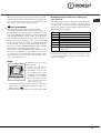
Kontrolka pracy TERMOSTATU
Sygnalizuje moment, w którym piekarnik grzeje. W momen-
cie osiàgni´cia zadanej temperatury pokr´t∏em termostatu
kontrolka zgaÊnie. W∏àczy si´ ponownie, kiedy grza∏ki zno-
wu zacznà grzaç a˝ do osiàgni´cia temperatury, kiedy zno-
wu zgaÊnie. Kontrolka informuje o prawid∏owej pracy termo-
statu, który czuwa nad utrzymaniem sta∏ej temperatury
w piekarniku.
OÊwietlenie piekarnika
Po ustawieniu pokr´t∏a OPCJI PRACY piekarnika w dowol-
nym po∏o˝eniu, poza po∏o˝eniem „0”, zapali si´ oÊwietlenie
piekarnika. Ustawienie pokr´t∏a na symbolu [symbol-˝ar-
ówka] umo˝liwia w∏àczenie oÊwietlenia piekarnika bez ko-
niecznoÊci w∏àczania ˝adnych elementów grzejàcych.
Podczas pieczenia oÊwietlenie piekarnika ca∏y czas jest
w∏àczone, ˝eby przypominaç nam o pracy urzàdzenia.
Programy pieczenia
PIECZENIE CIASTA
Pozycja pokr´t∏a termostatu: mi´dzy 50°C i Max.
W tej funkcji zaczyna dzia∏aç termoobieg i wszystkie ele-
menty zapewniajàce delikatne ciep∏o g∏ównie od do∏u. Ta
funkcja jest przeznaczona do gotowania delikatnych po-
traw, w szczególnoÊci ciast, które muszà wyrosnàç, co u∏a-
twia podgrzewanie od spodu.
Praktyczne rady:
• przed w∏o˝eniem potrawy piekarnik musi byç rozgrzany
• nie wolno piec wi´cej ni˝ jednà brytfann´
• potrawy nale˝y ustawiaç na kratce piekarnika
• kratk´ nale˝y wsunàç w pozycj´ nr 3
• nie otwieraç drzwi piekarnika w trakcie pieczenia
TRYB KONWENCJONALNY
Pozycja pokr´t∏a termostatu: mi´dzy 50°C i Max.
Gdy pokr´t∏o jest na tej pozycji zapala si´ lampka i w∏àcza-
jà dwa elementy grzejne piekarnika – dolny i górny. Ciep∏o
rozchodzi si´ równomiernie od do∏u i z góry. Jest to funkcja
zalecana do potraw z wo∏owiny i ciel´ciny wymagajàcych
powolnego przygotowani z ciàg∏ym uzupe∏nianiem p∏ynów.
Jest to równie˝ Êwietny system do pieczenia ciasteczek,
herbatników itp.. Przy w∏àczonym dolnym i górnym grzejni-
ku nale˝y u˝ywaç tylko jednej blachy lub rusztu, gdy˝ na kil-
ku powierzchniach temperatura rozchodzi si´ w niew∏aÊci-
wy sposób. JeÊli potrawa wymaga silniejszego ogrzewania
od do∏u lub z góry nale˝y wybraç ni˝szy lub wy˝szy poziom.
PIEKARNIK Z NAWIEWEM
Pozycja pokr´t∏a termostatu: mi´dzy 50°C i Max.
W trybie piekarnika z nawiewem wymuszana jest cyrkulacja
goràcego powietrza. Ruch powietrza wokó∏ potrawy wywo-
∏ywany jest przez wentylator znajdujàcy si´ w dolnej cz´Êci
piekarnika. To w∏aÊnie dzi´ki goràcemu powietrzu pieczona
potrawa przyrumienia si´ równomiernie i dok∏adnie. Dzi´ki
utrzymywaniu sta∏ej temperatury przez ca∏y czas pieczenia,
w trybie piekarnika z nawiewem istnieje mo˝liwoÊç równo-
czesnego pieczenia ró˝nych potraw, pod warunkiem, ˝e ich
czasy pieczenia sà jednakowe. W trybie tym mo˝na wyko-
rzystaç trzy pó∏ki jednoczeÊnie, patrz rozdzia∏ „równocze-
sne pieczenie na wielu pó∏kach”.
Kilka uwag na temat potraw, których przygotowywanie za-
lecane jest w tym trybie: tryb ten umo˝liwia uzyskanie do-
skona∏ych rezultatów przy pieczeniu daƒ wymagajàcych za-
piekania i dosyç d∏ugiego czasu pieczenia, na przyk∏ad: la-
zania, pieczone makarony, risotto, vol-au-vent, itp. Ponad-
to, dzi´ki doskona∏emu rozk∏adowi ciep∏a mo˝liwe jest sto-
sowanie ni˝szych temperatur do przygotowywania piecze-
ni. Dzi´ki ni˝szej temperaturze zmniejsza si´ wysychanie
i uzyskuje si´ bardziej kruche mi´so oraz zapobiega si´ je-
go kurczeniu. Tryb z nawiewem nadaje si´ szczególnie do-
brze do pieczenia ryb z minimalnym dodatkiem przypraw –
pozwala to na zachowanie ich smaku i wyglàdu. Doskona-
∏e rezultaty uzyskuje si´ równie˝ przy duszeniu warzyw, na
przyk∏ad: kapusty, rzepy, marchewki, cukini, bak∏a˝anów,
papryki.
Desery: tryb ten gwarantuje równie˝ osiàgni´cie wyÊmieni-
tych rezultatów przy pieczeniu ciast zakwaszanych, jak na
przyk∏ad biszkopt, bu∏eczki do herbaty, croissanty. Tryb
z nawiewem mo˝e byç stosowany do rozmra˝ania mi´sa,
ryb i chleba – po ustawieniu temperatury na 80°C – 100°C.
Aby rozmroziç bardziej delikatne potrawy, nale˝y ustawiç
pokr´t∏o termostatu na 50°C bàdê zastosowaç obieg zim-
nego powietrza, ustawiajàc termostat na 0°C.
GÓRNA GRZA¸KA
Pozycja pokr´t∏a wyboru temperatury: mi´dzy 50°C i Max.
W tym trybie, dania pieczone sà ciep∏em wypromieniowy-
wanym z elektrycznego elementu grzejnego umieszczone-
go w górnej cz´Êci piekarnika. Funkcja ta umo˝liwia przyru-
mienianie powierzchni mi´s i pieczeni pod koniec piecze-
nia.
GRILL
Pozycja pokr´t∏a wyboru temperatury: Max.
W tym trybie, dania pieczone sà ciep∏em wypromieniowy-
wanym z elektrycznego elementu grzejnego umieszczone-
go w górnej cz´Êci piekarnika. Wyjàtkowo wysoka tempera-
tura grilla, po∏àczona z jej bezpoÊrednim dzia∏aniem, umo˝-
liwia natychmiastowe przyrumienianie powierzchni mi´s
i pieczeni. Przysma˝ona powierzchnia pieczeni jest jedno-
czeÊnie barierà zapobiegajàcà wysychaniu dania. Funkcja
ta pozwala, wi´c na otrzymywanie soczystych i kruchych

daƒ mi´snych. Pieczenie w tym trybie zalecane jest przede
wszystkim do przygotowywania daƒ, które wymagajà wyso-
kich temperatur na powierzchni, jak na przyk∏ad ciel´cina
lub befsztyki, ˝eberka, filety, hamburgery, itp. ...
GRILL Z NAWIEWEM
Pozycja pokr´t∏a termostatu: mi´dzy 50°C i 200°C.
Tryb ten ∏àczy wielokierunkowe promieniowanie cieplne ele-
mentów grzejnych z cyrkulacjà goràcego powietrza. Po∏à-
czenie takie zapobiega przypalaniu si´ powierzchni potraw
oraz umo˝liwia dotarcie energii cieplnej do wn´trza daƒ.
Tryb ten nadaje si´ doskonale do pieczenia mieszanych –
warzywno-mi´snych kebabów, kie∏bas, ˝eberek, kotletów
z jagni´cia, kurczaków, przepiórek, itp. Ponadto doskonale
piecze tuƒczyka, steki z miecznika i nadziewanà màtw´, itp.
! Z funkcji pieczenia: GÓRNA GRZA¸KA, GRILL i RUSZT
nale˝y korzystaç przy zamkni´tych drzwiczkach.
! Korzystajàc z funkcji GÓRNA GRZA¸KA i GRILL kratk´ na-
le˝y umieÊciç na poziomie 5, a na poziomie 1 umieÊciç ta-
c´ na kapiàcy t∏uszcz. W przypadku funkcji RUSZT, kratk´
nale˝y umieÊciç na poziomie 2 lub 3 i na poziomie 1 umie-
Êciç tac´ na kapiàcy t∏uszcz.
Ro˝en
Z ro˝na korzysta si´ w nast´-
pujàcy sposób:
1. wsunàç tac´ na kapiàcy
t∏uszcz w prowadnic´ nr 1
2. zamontowaç ro˝en w otwo-
rze znajdujàcym si´ w tylnej
Êrodkowej cz´Êci piekarnika,
sprawdzajàcy czy przednie
po∏àczenie ro˝na umiesz-
czone zosta∏o poprawnie
w ramce mocujàcej
3. zdemontowaç plastikowy uchwyt i uruchomiç silnik obra-
cajàcy ro˝en za pomocà pokr´t∏a wyboru funkcji, usta-
wiajàc w pozycji
4. Uruchomiç grza∏k´ grilla pokr´t∏em termostatu, pozycja Max
20
PL
Wskazówki dotyczàce korzystania z elektrycznej
p∏yty grzewczej
Aby uniknàç rozpraszania energii cieplnej i przypalania daƒ,
nale˝y stosowaç wy∏àcznie garnki o p∏askich dnach,
o Êrednicach nie mniejszych od Êrednicy p∏ytki. W poni˝szej
tabeli przedstawiono zalecane po∏o˝enia pokr´te∏ do przy-
gotowywania ró˝nych potraw.
Przed pierwszym u˝yciem elektrycznej p∏ytki grzejnej, nale-
˝y jà wygrzaç przez oko∏o 4 minuty w maksymalnej tempe-
raturze bez garnków.
Po∏o˝enie P∏ytka normalna lub szybko nagrzewajàca si´
0 wy∏àczona
1 gotowanie warzyw, ryb
2 gotowanie kartofli (na parze), zup, ciecierzycy, fasoli
3 dalsze gotowanie du˝ych iloÊci jedzenia, minestrone
4 pieczenie (Êrednia intensywnoÊç)
5 pieczenie (bardziej intensywne)
6 przyrumienianie i osiàganie temperatury wrzenia
wkrótkim czasie
Strona się ładuje...
Strona się ładuje...
Strona się ładuje...
Strona się ładuje...
Strona się ładuje...
Strona się ładuje...
Strona się ładuje...
Strona się ładuje...
Strona się ładuje...
Strona się ładuje...
Strona się ładuje...
Strona się ładuje...
Strona się ładuje...
Strona się ładuje...
Strona się ładuje...
Strona się ładuje...
-
 1
1
-
 2
2
-
 3
3
-
 4
4
-
 5
5
-
 6
6
-
 7
7
-
 8
8
-
 9
9
-
 10
10
-
 11
11
-
 12
12
-
 13
13
-
 14
14
-
 15
15
-
 16
16
-
 17
17
-
 18
18
-
 19
19
-
 20
20
-
 21
21
-
 22
22
-
 23
23
-
 24
24
-
 25
25
-
 26
26
-
 27
27
-
 28
28
-
 29
29
-
 30
30
-
 31
31
-
 32
32
-
 33
33
-
 34
34
-
 35
35
-
 36
36


Indesit KN3N65SA/BG instrukcja
- Kategoria
- Piekarniki
- Typ
- instrukcja
- Niniejsza instrukcja jest również odpowiednia dla
Powiązane artykuły
-
Whirlpool K6 C51/R Instrukcja obsługi
-
Indesit KN3T760SA(W)/U instrukcja
-
-
-
-
-
Indesit C 34S P4 (X) U instrukcja
-
Indesit K3G55.A(W)/U instrukcja
-
-
