Bartscher 200254 Instrukcja obsługi
- Kategoria
- Przycinarki do trawy
- Typ
- Instrukcja obsługi
Niniejsza instrukcja jest również odpowiednia dla

BMS1781 – BMS1783 – BMS1785
CTS1757 – CTS1759 – CTS1761
CSS1750 – CSS1752 – CSS1754
CLS2760C – CLS2770C
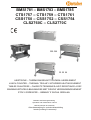
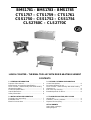
HEIZTISCHE – THERMOWAGEN MIT TROCKEN- HEIZELEMENT
LUNCH COUNTER – THERMAL TROLLEY WITHDRIED HEATING ELEMENT
TABLES CHAUFFEES – CHARIOTS TERMIQUES AVEC RESISTANCE A SEC
Operation and maintenance manual
Manuel d’emploi et d’entretien
Betriebs-und Wartungsanleitung
WARMHOUDTAFELS-BAIN-MARIES MET DROOG VERWARMINGELEMENT
STOLY GRZEWCZE – BEMARY Z SUCHA GRZALKA
Gebruiksaanwijzing en onderhoudshandleiding
Instrukcja obslugi i konserwacji

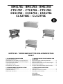
BMS1781 – BMS1783 – BMS1785
CTS1757 – CTS1759 – CTS1761
CSS1750 – CSS1752 – CSS1754
CLS2760C – CLS2770C
HEIZTISCHE – THERMOWAGEN MIT TROCKEN-HEIZWIDERSTAND
INHALT
1 ALLGEMEINE INFORMATIONEN
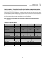
Zweck des Handbuchs………………………………
Identifikation des Herstellers und der Maschine….
Beschreibung der Heiztische und Thermowagen...
Technische Eigenschaften…………………………..
Außenabmessungen…………………………………
Informationen zur Sicherheit………………………..
2 INFORMATIONEN ZUR INSTALLATION
Verpackung und Auspacken………………………..
Installationsbereich…………………………………..
Elektrischer Anschluss………………………………
4
4
5
5
6
6
7
7
7
3 INFORMATIONEN ZUR BEDIENUNG UND
REINIGUNG
Beschreibung der Bedienungselemente………….
Bedienungshinweise.......................................…..
Benutzung der Heiztische und Thermowagen…...
Reinigung am Tagende……………………………..
Längere Außerbetriebsetzung der Maschine…….
4 FEHLERSUCHE, RECYCLING
Vorbemerkung……………………………………….
Störungen, Ursachen, Behelfe……………………..
Entsorgung und Recycling………………………….
ANLAGEN
Ersatzteilkatalog
Elektrischer Schaltplan
8
8
8
8
8
9
9
9

4
ALLGEMEINE
INFORMATIONEN
1
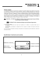
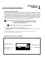
Zweck des Handbuchs
Dieses Handbuch wurde vom Hersteller verfasst und ist Bestandteil der Maschinenausstattung. Der
Hersteller hat in der Entwicklungs- und Konstruktionsphase ein besonderes Augenmerk auf die Aspekte
gerichtet, die Risiken hinsichtlich der Sicherheit und Gesundheit der mit der Maschine interagierenden
Personen bedeuten könnten. Neben der Einhaltung der zuständigen gesetzlichen Vorschriften hat der
Hersteller alle “Regeln der guten Konstruktionstechnik” befolgt. Zweck dieser Informationen ist es, den
Anwender sensibel für die Vorbeugung jeglichen Risikos zu machen. Umsichtiges Arbeiten ist in jedem Fall
unverzichtbar. Die Sicherheit liegt auch in den Händen aller Bediener, die mit der Maschine interagieren.
Bewahren Sie dieses Handbuch an einem geeigneten Ort auf, sodass dieses im Bedarfsfall stets sofort
greifbar ist. Zur besonderen Hervorhebung einiger Textstellen wurden folgende Symbole eingeführt:
GEFAHR - ACHTUNG: Weist auf Gefahren hin, die schwere Verletzungen hervorrufen
können. Hier ist besondere Vorsicht geboten.
INFORMATIONEN: Technische Angaben von besonderer Wichtigkeit.
Diesem Handbuch werden folgende Unterlagen beigefügt:
- Garantieurkunde mit den vom Hersteller vorgegebenen Garantiebedingungen.
- Dokumente zum Nachweis der Übereinstimmung mit den geltenden Gesetzen betreffend die Sicherheit
und Gesundheit von Personen.
Bei allen Anforderungen des Technischen Kundendienstes, Fragen und Ersatzteilbestellungen nehmen Sie
Kontakt mit dem autorisierten Händler auf.
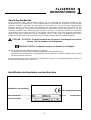
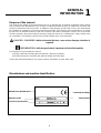
Identifikation des Herstellers und der Maschine
Identifikation des Herstellers
Maschinenmodell
Technische Daten
CE Konformitätszeichen
Seriennummer

5
ALLGEMEINE
INFORMATIONEN
1
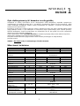
Beschreibung der Heiztische und Thermowagen mit Trocken-
Heizwiderstand
Diese Maschine wurden eigens entwickelt, um die Temperatur von Lebensmitteln konstant zu halten und zu
verhindern, dass diese unter 65° C sinkt. Die Maschinen zeichnen sich durch eine sehr einfache
Konstruktionsweise aus, wodurch die Möglichkeiten des Auftretens von Störungen auf ein Minimum reduziert
und Wartungsarbeiten erleichtert werden.
Die Tragkonstruktion ist vollständig in Inox-Stahlblech AISI 304 18/10 ausgeführt. Die Wasserbad-Wannen
haben eine Doppelwand, unverzichtbar zur Erhaltung der vom Heizsystem erzeugten Wärme. Die
Innenwanne wurde ausgelegt zur Aufnahme von GN-Schalen für bis zu 200 Stunden oder für andere
lebensmitteltaugliche Behälterarten.
Der obere Teil der Thermowagen Mod.CSS1750/1752/1754 wird mit einem Klappdeckel verschlossen, der
sich stufenweise öffnen lässt, wodurch eine bessere Wärmeisolierung gewährleistet wird.
Sämtliche verschiedenen Thermowagen-Modelle sind mit vier pirouettierenden Rädern ausgestattet, sodass
diese leicht bewegt werden können.
N.B. : Geben Sie in keinem Fall Wasser in die Innenwanne der Thermowagen-Heiztische.
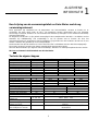
Technische Eigenschaften
Beschreibungen Maßeinheit BMS1781 BMS1783 BMS1785
Nennleistung W 2000 2000 2000
Nettogewicht kg 14 20 30
Gewicht mit Verpackung kg 17 24 35
Installation Auf der Werkbank
Beschreibungen Maßeinheit CTS1757 CTS1759 CTS1761
Nennleistung W 2000 2000 2000
Nettogewicht kg 24 32 45
Gewicht mit Verpackung kg 27 36 50
Installation Am Boden
Beschreibungen Maßeinheit CSS1750 CSS1752 CSS1754
Nennleistung W 2000 2000 2000
Nettogewicht kg 26 35 48
Gewicht mit Verpackung kg 29 39 53
Installation Am Boden
Beschreibungen Maßeinheit CLS2760C CLS2770C
Nennleistung W 2000 2000
Nettogewicht kg 55 70
Gewicht mit Verpackung kg 67 82
Installation Am Boden
Elektrische
Stromversorgung
V Hz Ph 230V 50Hz 1Ph
Schutzgrad IPX4
Schutz gegen Stromschlag Klasse I
Übereinstimmung mit
Richtlinien und Normen
73/23/EWG - 93/68/EWG – 93/44/EWG - 89/336/EWG
89/109/EWG

6
ALLGEMEINE
INFORMATIONEN
1
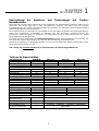
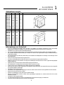
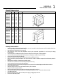
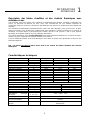
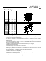
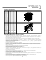
Außenabmessungen
mm
ABC
BMS1781
BMS1783
BMS1785
CTS1757
CTS1759
CTS1761
CSS1750
CSS1752
CSS1754
CLS2760C
CLS2770C
650
850
1150
650
850
1150
650
850
1150
890
1230
550
650
650
550
650
650
550
650
650
650
650
450
450
450
450
450
450
450
450
450
950
950
mm
ABC
BMS1781
BMS1783
BMS1785
CTS1757
CTS1759
CTS1761
CSS1750
CSS1752
CSS1754
CLS2760C
CLS2770C
600
780
1100
650
840
1170
650
840
1170
890
1230
490
600
600
560
650
650
560
650
650
650
650
320
320
320
850
850
850
850
850
850
950
950
Informationen zur Sicherheit
• Es ist von grundlegender Wichtigkeit, dieses Handbuch vor Installation und Gebrauch aufmerksam zu lesen. Die ständige
Befolgung der im Handbuch enthaltenen Anweisungen gewährleisten die Sicherheit von Mensch und Maschine.
• Manipulieren Sie in keinem Fall die Sicherheitseinrichtungen
• Die von den zuständigen Stellen in jedem Land herausgegebenen Arbeitssicherheitsvorschriften sind unbedingt einzuhalten.
• Der Hersteller übernimmt keinerlei Haftung für Schäden an Personen oder Gegenständen infolge der Nichtbeachtung von
Sicherheitsvorschriften.
• Die korrekte Aufstellung der Maschine, Beleuchtung und Sauberkeit des Arbeitsplatzes sind wichtige Voraussetzungen für die
Personalsicherheit.
• Setzen Sie die Maschine keinen äußeren Agenzien aus.
• Anschluss und Inbetriebnahme der Maschine sind nur von technischem Fachpersonal durchzuführen.
• Stellen Sie sicher, dass die Kenndaten der Anlage am Aufstellungsort der Maschine den auf dem Typenschild eingeprägten
Werten entsprechen.
• Stellen Sie sicher, dass die Maschine mit einer Erdungsanlage verbunden ist.
• Der Arbeitsbereich um die Maschine herum ist stets sauber und trocken zu halten.
• Tragen Sie die von den Unfallverhütungsvorschriften vorgesehene Schutzkleidung.
• Diese Maschine darf nur für den vorgesehenen Einsatzbereich verwendet werden. Jeder andere Einsatz ist als unsachgemäß
und somit als gefährlich zu betrachten.
• Überladen Sie die Maschine niemals.
• Das Einführen von Gegenständen, Werkzeugen sowie das Greifen mit den Händen ins Innere gefährlicher Teile ist verboten.
• Kinder sind von der Maschine fern zu halten.
• Ziehen Sie den Netzstecker, wenn die Maschine nicht benutzt wird.
• Nehmen Sie bei Defekten und/oder Schäden keine eigenständigen Reparaturen vor, sondern wenden Sie sich an einen
autorisierten Händler.
• Verlangen Sie stets Originalersatzteile.
• Vor der Reinigung der Maschine ziehen Sie den Netzstecker, um die Stromversorgung zu unterbrechen.
• Verwenden Sie zur Reinigung der Maschine keine Wasserstrahlen.

7
INFORMATIONEN ZUR
INSTALLATION
2
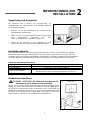
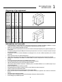
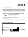
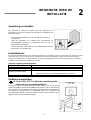
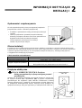
Verpackung und Auspacken
Die Maschine wird in Karton mit Styroporeinlage zur
Gewährleistung der vollkommenen Unversehrtheit während
des Transports verpackt.
• Befolgen Sie bei der Handhabung der Verpackung die
nachstehenden Anweisungen.
• Öffnen Sie die Packung und prüfen Sie die Unversehrtheit
aller Komponenten. Bewahren Sie das
Verpackungsmaterial für zukünftige Umzüge auf.
• Heben Sie die Maschine so wie angegeben an und
positionieren diese im vorgesehenen Installationsbereich.
Installationsbereich
Der vorgesehene Bereich muss ausreichend beleuchtet sein und über eine Steckdose zur Abgabe
elektrischen Stroms verfügen. Die Stützfläche muss groß genug, gut nivelliert und trocken sein. Die
Installation hat in nicht explosionsgefährdeten Umgebungen zu erfolgen. In jedem Fall ist die Installation
auch unter Beachtung der geltenden gesetzlichen Vorschriften zur Arbeitssicherheit durchzuführen.
Tabelle mit Umgebungsbedingungen
Beschreibungen Werte
Betriebstemperatur: 0÷35 °C (32÷95 °F)
Lagertemperatur -15 bis +65 °C (von –6.8 bis +149 °F)
Relative Luftfeuchtigkeit
Maximal 80% bei einer Umgebungstemperatur von 20 °C
Maximal 50% bei einer Umgebungstemperatur von 20÷60 °C
Staubaufkommen unter 0.03 g/m³
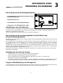
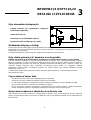
Elektrischer Anschluss
GEFAHR - ACHTUNG: Der elektrische Anschluss an das
Stromnetz ist durch Fachpersonal herzustellen
Einphasen-Anschluss
230V – 1Ph
Stellen Sie die perfekte Wirksamkeit der Erdungsanlage im Betrieb sicher.
Stellen Sie sicher, dass Leitungsspannung (V) und -frequenz (Hz) den für
die Maschine vorgesehenen Werten entsprechen (siehe Typenschild und
elektrischen Schaltplan). Die Maschine ist mit einem Elektrokabel zum
Anschluss eines Mehrpolsteckers ausgestattet. Der Stecker ist mit einem
Wandschalter zu verbinden, der mit Differential ausgestattet ist.

8
INFORMATIONEN ZUR
BEDIENUNG UND
REINIGUNG
3
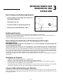
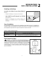
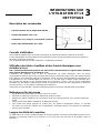
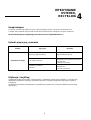
Beschreibung der Bedienungselemente
- Kontroll-Lampe (A) zur Anzeige des Erreichens der
eingestellten Temperatur
- Thermostat 0°-90°C (B)
- Last-Trennschalter (C) mit Spannungsanzeige
- Eingang für Versorgungskabel (D) + Kabel
Bedienungshinweise
Entfernen Sie vor der Benutzung des Geräts den Spezialschutzfilm, falls vorhanden.
Der während der ersten Betriebsminuten auftretende unangenehme Geruch ist auf das Vorhandensein von
Arbeitsfettrückständen zurückzuführen.
Heizen Sie beim ersten Einschalten das Gerät auf die maximale Temperatur auf.
Beschreibung der Heiztische und Thermowagen mit Trocken-
Heizwiderstand
N.B: Geben Sie in keinem Wasser in die Wanne, da es sich um Heiztische und Thermowagen mit
Trockenwiderständen handelt.
Bei der Installation der Geräte sind die Stromstecker in die entsprechend für den Aufstellungsraum
vorgesehenen Steckdosen zu stecken. Für den Betrieb der Geräte ist der Hauptschalter zu drücken, dieser
leuchtet auf. Drehen Sie den Thermostatknopf und stellen Sie die gewünschte Temperatur ein (mindestens
65°C). Auf diese Weise leuchtet die rote Kontroll-Lampe auf, um den störungsfreien Betrieb des Widerstands
anzuzeigen. Nach dem Erreichen der gewünschten Temperatur geht die Lampe aus und leuchtet jedesmal
dann wieder auf, wenn sich die Temperatur entsprechend gesenkt hat (um zirka 5° C).
Am Ende des täglichen Einsatzes stellen Sie den Hauptschalter ab und lassen die eingestellte Temperatur
unverändert.
Reinigung am Tagende
• Ziehen Sie am Ende des Arbeitstages den Netzstecker.
• Reinigen Sie das Gerät sorgfältig unter Verwendung neutraler Produkte.
• Reinigen Sie die Außenseiten der vollkommen abgekühlten Maschine mit einem feuchten Schwamm.
• Verwenden Sie keine Stahlwollen oder Scheuermittel.
• Zur Vermeidung der Gefahren durch Berührung sehr heißer Teile ist auf die Bereiche mit konstanter
Temperatur unbedingt erst nach den für die Wartung vorgesehenen Eingriffen zuzugreifen.
Längere Außerbetriebsetzung der Maschine
Wenn die Maschine für längere Zeit außer Betrieb gesetzt werden soll, stellen Sie den Hauptschalter an der
Wand ab, führen eine allgemeine Reinigung der Maschine durch und bedecken diese mit einem Tuch zum
Schutz gegen Staub.

9
FEHLERSUCHE,
RECYCLING
4
Vorbemerkung
Bei Defekten oder Betriebsstörungen ziehen Sie den Netzstecker und nehmen Kontakt mit dem
Technischen Kundendienst Ihres Händlers auf. Montieren Sie nicht die internen Teile der Maschine ab.
Der Hersteller übernimmt keinerlei Haftung für eventuelle Manipulationen!
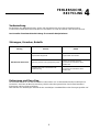
Störungen, Ursachen, Behelfe
Störung Ursache Behelf
Hauptschalter abgestellt
Hauptschalter einschalten
Die Maschine heizt nicht
Spannung auf der Versorgungsleitung fehlt
Nehmen Sie Kontakt mit dem
Technischen Kundendienst Ihres
Händlers auf
Heizwiderstand oder Thermostat nicht
funktionstüchtig
Nehmen Sie Kontakt mit dem
Technischen Kundendienst Ihres
Händlers auf
Entsorgung und Recycling
Die Maschine wurde für eine durchschnittliche Lebensdauer von 10.000 Betriebsstunden entwickelt und
konstruiert.. Am Ende der Maschinennutzung sind die nationalen gesetzlichen Vorschriften betreffend
Entsorgung und Recycling zu befolgen.
Bitte nehmen Sie diesbezüglich Kontakt mit den zuständigen Umweltbehörden oder Entsorgungsstellen auf.

BMS1781 – BMS1783 – BMS1785
CTS1757 – CTS1759 – CTS1761
CSS1750 – CSS1752 – CSS1754
CLS2760C – CLS2770C
LUNCH COUNTER – THERMAL TROLLEY WITH DRIED HEATING ELEMENT
CONTENTS
1 GENERAL INFORMATION
Purpose of the manual………………………………
Manufacturer and machine identification…………..
Lunch counter – thermal trolley with dried heating
element description…………………………………..
Technical specifications………………………….….
Overall dimensions…………………………………..
Safety information………………….………………...
2 INSTALLATION INFORMATION
Packaging and unpacking…………………………...
Installation area………………………………………
Electrical connections ……………………………….
4
4
5
5
6
6
7
7
7
3 USE AND CLEANING INFORMATION
Control descriptions…………………………………
Recommendations for use …………………………
Lunch counter – thermal trolley with dried heating
element use …………………………………………
End of the day cleaning ….………………………...
Extended periods of disuse ………………………..
4 TROUBLE SHOOTING, RECYCLING
Introduction…………………………………………..
Problems, causes, solutions……………………….
Disposal and recycling……………………………...
ATTACHMENTS
Spare parts catalogue
Wiring diagram
8
8
8
8
8
9
9
9

4
GENERAL
INFORMATION
1
Purpose of the manual
This manual was written by the Manufacturer and is an integral part of machine equipment. During design
and construction the Manufacturer has carefully considered possible hazards and personal risks that may
result from interaction with the machine. In addition to observing the specific laws in force, the manufacturer
has adopted all “exemplary construction technique principles”. The purpose of this information is to advise
the users to use extreme caution to avoid risks. However, discretion is invaluable. Safety is also in the hands
of all the operators who interact with the machine. Keep this manual in a suitable place, always within reach
for consultation. The following symbols are included to better stress some passages:
DANGER – WARNING: indicates hazards that may cause serious damages; attention is
required.
INFORMATION: indicates particularly important technical information.
The following is enclosed with this manual:
- Warranty certificate describing the Manufacturer’s warranty conditions.
- Documents that prove conformity with effective health and safety laws.
Contact the Authorised dealer for any service request, information or spare parts order.
Manufacturer and machine identification
Manufacturer Identification
Machine model
Technical specifications
Conformity markings
Serial number

5
GENERAL
INFORMATION
1
Lunch counter – Thermal trolley with dried heating elements description
This equipment is specifically designed to keep temperature of food constant and over 65°C. It is
characterised by a highly simplified construction in order to reduce the possibility of malfunctions to a
minimum and facilitate maintenance.
Their structure is fully constructed with AISI 304 18/10 stainless steel sheet metal, while bain-marie basins
are double walled to keep the heat produced by the heating system. The internal basin has been designed to
hold G.N. trays for up to 200 hours or other types of food containers.
The top of thermal trolleys mod. CSS1750/1752/1754 has a compass type cover to guarantee a better heat
insulation.
All models of thermal trolleys have four castor wheels to allow easy movement.
Note : Absolutely do not pour water in the internal basin of lunch counters and thermal trolleys.
Technical specifications
Descriptions Unit of measure BMS1781 BMS1783 BMS1785
Nominal power W 2000 2000 2000
Net weight Kg 14 20 30
Packaged weight Kg 17 24 35
Installation Counter
Descriptions Unit of measure CTS1757 CTS1759 CTS1761
Nominal power W 2000 2000 2000
Net weight Kg 24 32 45
Packaged weight Kg 27 36 50
Installation Stand-alone
Descriptions Unit of measure CSS1750 CSS1752 CSS1754
Nominal power W 2000 2000 2000
Net weight Kg 26 35 48
Packaged weight Kg 29 39 53
Installation Stand-alone
Descriptions Unit of measure CLS2760C CLS2770C
Nominal power W 2000 2000
Net weight Kg 55 70
Packaged weight Kg 67 82
Installation Stand-alone
Power supply V Hz Ph 230V 50Hz 1Ph
Protection level IPX4
Electrical shock protection Class I
Conformity with directives
and norms
73/23/EEC - 93/68/EEC – 93/44/EEC - 89/336/EEC
89/109/EEC

6
GENERAL
INFORMATION
1
Overall dimensions
mm
ABC
BMS1781
BMS1783
BMS1785
CTS1757
CTS1759
CTS1761
CSS1750
CSS1752
CSS1754
CLS2760C
CLS2770C
650
850
1150
650
850
1150
650
850
1150
890
1230
550
650
650
550
650
650
550
650
650
650
650
450
450
450
450
450
450
450
450
450
950
950
mm
ABC
BMS1781
BMS1783
BMS1785
CTS1757
CTS1759
CTS1761
CSS1750
CSS1752
CSS1754
CLS2760C
CLS2770C
600
780
1100
650
840
1170
650
840
1170
890
1230
490
600
600
560
650
650
560
650
650
650
650
320
320
320
850
850
850
850
850
850
950
950
Safety information
• Careful consultation of this manual before installation and use is essential. Continual observance of the indications found in the
manual guarantee personal and machine safety.
• Never tamper with safety devices for any reason.
• Strict observance of the work safety regulations issued by the responsible organisations in each country is strongly
recommended.
• The manufacturer is not liable for damages to persons or things due to the neglect of safety regulations.
• Correct machine placement, illumination and cleanliness are important conditions for personal safety.
• Do not expose the machine to the elements.
• Machine connections and start-up must only be performed by qualified technicians.
• Make sure that the system specifications of the room where the machine is installed correspond to the information printed on
the plate.
• Make sure the machine is connected to a grounding system.
• The work area around the machine must always be kept clean and dry.
• Use the garments foreseen by work safety regulations.
• This machine must only be used for its specific purpose; any other use is considered improper and therefore hazardous.
• Do not overload the machine.
• Introducing objects, tools, hands or other within hazardous parts is forbidden.
• Keep the machine away from children.
• Disconnect the power cord from the electrical socket when the machine is not in use.
• In the event of malfunctions and/or problems, do not attempt to repair the machine. Contact the authorised dealer.
• Use original spare parts.
• Before cleaning the machine, disconnect the power supply by unplugging the machine.
• Do not clean with running water.

7
INSTALLATION
INFORMATION
2
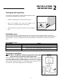
Packaging and unpacking
The machine is packaged in cardboard with polystyrene inserts
to guarantee full integrity during transport.
• Handle the packaging according to the instructions.
• Open the packaging and check the integrity of all
components. Keep packaging for future moves.
• Lift the machine as indicated and place it in the installation
area.
Installation area
The arranged area must be suitably illuminated and an electrical socket must be available. The resting
surface must be sufficiently ample, even and dry. The machine must be installed in rooms with non-explosive
environments. In any case, installation must also be performed in consideration of the work safety laws in
force.
Room conditions table
Descriptions Values
Working temperature 0÷35 °C (32÷95 °F)
Storage temperature -15 to +65 °C (from –6.8 to +149 °F)
Relative humidity
Maximum 80% with 20 °C room temperature
Maximum 50% with room temperature between 20÷60 °C
Dustiness Less than 0.03 g/m³
Electrical connections
DANGER – WARNING: Electrical connections to the supply
mains must be performed by qualified personnel.
Connection
single-phase
230V – 1Ph
Verify the efficiency of the grounding system in the building. Make sure that
line voltage (V) and frequency (Hz) correspond to those of the machine
(See the identification plate and wiring diagram). The machine is equipped
with a power cord that connects to a multi-polar plug. The plug is to be
connected to a wall switch equipped with a circuit breaker.

8
USE AND CLEANING
INFORMATION
3
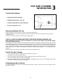
Control descriptions
- Temperature indicator light (A)
- Adjustment thermostat 0°- 90°C (B)
- Loaded circuit breaker (C) with voltage led
- Power cord inlet (D) + cord
Recommendations for use
Before using the machine remove, if found, the special protective film.
Unpleasant odours produced during the first minutes of operation are due to the presence of processing
grease residues.
On first use, heat the machine to the maximum temperature.
Lunch counter and thermal trolley with dried heating elements use
Note: absolutely do not pour water in the basins since these lunch counters and thermal trolleys
have dried heating elements.
The equipment must be installed connecting the power cords to the proper sockets foreseen in the working
environment where they must be placed. To turn the machine on, press the main switch -it will light up- and
turn the thermostat knob to set the required temperature (al least 65°C); the red led will light up indicating
that the resistance is working correctly. Once the required temperature has been reached, the led will turn off
and it will turn back on when the temperature decreases enough (approximately 5° C) to justify resistance
functions.
At the end of the day, turn the main switch off, leaving the temperature set.
End of the day cleaning
• Remove the plug from the electrical socket at the end of the day.
• Accurately clean using neutral products.
• Clean external machine parts with a damp sponge when the machine is fully cooled.
• Do not use metallic pads and abrasive detergents.
• To avoid hazards caused by contact with high temperature parts, only access heating parts after
maintenance operations have been completed.
Extended periods of disuse
For extended periods of disuse, turn off the main wall switch, clean the machine and cover it with a cloth to
protect if from dust.

9
TROUBLE SHOOTING,
RECYCLING
4
Introduction
In the event of breakdown or malfunctioning, disconnect the plug from the socket and contact your Dealer’s
service centre. Avoid dismantling internal machine parts.
The manufacturer is not liable for any machine tampering!
Problems, causes, solutions
Problem Cause Solution
Main switch off Turn on main switch
The machine does not heat
No voltage on the power supply Contact your dealer’s service centre
Resistance or thermostat broken Contact your dealer’s service centre
Disposal and recycling
The machine was designed and constructed to work for an average of 10.000 hours. When finished using
the machine, follow national laws for disposal and recycling.
Please contact the environmental authorities or authorised organisations.

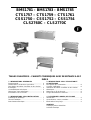
BMS1781 – BMS1783 – BMS1785
CTS1757 – CTS1759 – CTS1761
CSS1750 – CSS1752 – CSS1754
CLS2760C – CLS2770C
TABLES CHAUFFEES – CHARIOTS THERMIQUES AVEC RESISTANCE A SEC
INDEX
1 INFORMATIONS GENERALES
But du manuel………………………………………..
Identification Constructeur et machine……….……
Description des tables chauffées et des chariots
thermiques…………………………………………….
Caractéristiques techniques………………………...
Dimensions d’encombrement……………………….
Informations sur la sécurité………………….………
2 INFORMATIONS SUR L’INSTALLATION
Emballage et déballage……………………………..
Zone d’installation……………………………………
Branchement électrique……………………….…….
4
4
5
5
6
6
7
7
7
3 INFORMATIONS SUR L’UTILISATION ET
LE NETTOYAGE
Description des commandes……………………….
Conseils d’utilisation………………………………..
Utilisation des tables chauffées et des chariots
thermiques……………………………………………
Nettoyage en fin de journée………………………..
Longue inactivité de la machine…………………...
4 RECHERCHE PANNES, RECYCLAGE
Introduction…………………………………………..
Inconvénients, causes, remèdes…………………..
Elimination et recyclage…………………………….
ANNEXES
Catalogue pièces détachées
Schéma électrique
8
8
8
8
8
9
9
9

4
INFORMATIONS
GENERALES
1
But du manuel
Ce manuel a été rédigé par le constructeur et représente une partie intégrante de la dotation de la machine.
Le constructeur, en phase d’étude et de construction, a prêté une attention particulière aux aspects qui
peuvent provoquer des risques à la sécurité et à la santé des personnes qui interagissent avec la machine.
Outre le respect des lois en vigueur en la matière, il a adopté toutes les “règles de la bonne technique de
construction”. Le but de ces informations est de sensibiliser les utilisateurs à être particulièrement attentifs
pour prévenir tous les risques. La prudence est quoi qu’il en soit irremplaçable. La sécurité est également
dans les mains de tous les opérateurs qui interagissent avec la machine. Conserver ce manuel dans un
endroit approprié, afin de l’avoir toujours à la portée de la main pour sa consultation. Pour mettre en
évidence certaines parties du texte, les symboles suivants ont été utilisés:
DANGER – ATTENTION: indique les dangers qui peuvent provoquer de graves lésions;
il est nécessaire de prêter attention.
INFORMATIONS: indications techniques particulièrement importantes.
A ce Manuel sont joints:
- Le certificat de garantie dans lequel sont reportées les conditions de garantie dictées par le
Constructeur.
- Les documents qui attestent la conformité aux lois en vigueur en matière de sécurité et santé des
personnes.
Pour toute demande d’Assistance technique, informations et commandes de pièces détachées, contacter le
Revendeur autorisé.
Identification Constructeur et machine
Identification Constructeur
Modèle machine
Données techniques
Marque de conformité
Numéro de matricule

5
INFORMATIONS
GENERALES
1
Description des tables chauffées et des chariots thermiques avec
résistance à sec
Ces machines sont nées exprès pour maintenir la température des aliments constante, empêchant que
celle-ci ne descende au-dessous de 65°C. Elles sont caractérisées par une extrême simplicité de
construction faite pour réduire au minimum la possibilité que des pannes se produisent et d’en faciliter leur
entretien.
Leur structure est entièrement constituée de tôle d’acier inox AISI 304 18/10, alors que les bacs du bain-
marie sont formés d’une double paroi, indispensable pour maintenir la chaleur produite par le système de
chauffage. Le bassin interne a été projeté pour contenir des bacs G.N. jusqu’à h. 200 ou pour d’autres
typologies de récipients indiqués pour une utilisation alimentaire.
Les chariots thermiques mod. CS1751/1753/1755 ont la partie supérieure fermée par un couvercle ouvrant à
compas, de façon à garantir une meilleure isolation de la chaleur.
Tous les différents modèles de chariots thermiques sont dotés de quatre roues pivotantes, de façon à être
facilement déplacés.
N.B. : Ne mettre absolument jamais d’eau dans le bac interne des tables chauffées des chariots
thermiques.
Caractéristiques techniques
Descriptions Unité de mesure BMS1781 BMS1783 BMS1785
Puissance nominale W 2000 2000 2000
Poids net Kg 14 20 30
Poids avec emballage Kg 17 24 35
Installation Sur comptoir
Descriptions Unité de mesure CTS1757 CTS1759 CTS1761
Puissance nominale W 2000 2000 2000
Poids net Kg 24 32 45
Poids avec emballage Kg 27 36 50
Installation A terre
Descriptions Unité de mesure CSS1750 CSS1752 CSS1754
Puissance nominale W 2000 2000 2000
Poids net Kg 26 35 48
Poids avec emballage Kg 29 39 53
Installation A terre
Descriptions Unité de mesure CLS2760C CLS2770C
Puissance nominale W 2000 2000
Poids net Kg 55 70
Poids avec emballage Kg 67 82
Installation A terre
Alimentation d’énergie
électrique
V Hz Ph
230V 50Hz 1Ph
Degré de protection IPX4
Protection contre la
secousse électrique
Classe I
Conformité aux directives et
normes
73/23/CEE - 93/68/CEE – 93/44/CEE - 89/336/CEE
89/109/CEE

6
INFORMATIONS
GENERALES
1
Dimensions d’encombrement
mm
ABC
BMS1781
BMS1783
BMS1785
CTS1757
CTS1759
CTS1761
CSS1750
CSS1752
CSS1754
CLS2760C
CLS2770C
650
850
1150
650
850
1150
650
850
1150
890
1230
550
650
650
550
650
650
550
650
650
650
650
450
450
450
450
450
450
450
450
450
950
950
mm
ABC
BMS1781
BMS1783
BMS1785
CTS1757
CTS1759
CTS1761
CSS1750
CSS1752
CSS1754
CLS2760C
CLS2770C
600
780
1100
650
840
1170
650
840
1170
890
1230
490
600
600
560
650
650
560
650
650
650
650
320
320
320
850
850
850
850
850
850
950
950
Informations sur la sécurité
• Il est fondamental de consulter attentivement ce manuel avant de procéder aux opérations d’installation et utilisation. Le respect
constant des indications contenues dans le manuel garantit la sécurité de la personne et de la machine.
• N’altérer sous aucun prétexte les dispositifs de sécurité.
• Nous recommandons le respect rigoureux des normes de sécurité sur le travail promulguées par les organismes préposés dans
chaque nation.
• Le constructeur décline toute responsabilité pour les dommages aux personnes ou aux choses, causés par le manque de respect
des normes de sécurité.
• La disposition correcte de la machine, l’illumination et le nettoyage du lieu, sont des conditions importantes pour la sécurité
personnelle.
• Ne pas exposer la machine aux agents atmosphériques.
• Le branchement et la mise en service de la machine doivent être effectués uniquement par le personnel technique spécialisé.
• Vérifier que les caractéristiques de l’installation où doit être installée la machine correspondent aux données poinçonnées sur la
plaquette.
• S’assurer que la machine soit branchée à une installation de mise à la terre.
• La zone de travail autour de la machine doit toujours être maintenue propre et sèche.
• Utiliser les vêtements prévus par les normes anti-accidents sur le travail.
• Cette machine doit être destinée uniquement à l’utilisation prévue; une utilisation différente est à considérer impropre et par
conséquent dangereuse.
• Ne pas surcharger la machine au-delà de sa capacité.
• Il est interdit d’introduire des objets, des outils, les mains ou autre à l’intérieur des parties dangereuses.
• Garder la machine hors de la portée des enfants.
• Débrancher la fiche de la prise de courant lorsque la machine n’est pas utilisée.
• En cas de pannes et/ou inconvénients d’utilisation, ne pas effectuer soi-même les réparations mais s’adresser au Revendeur
autorisé.
• Demander les pièces détachées originales.
• Avant de procéder au nettoyage de la machine, ôter l’alimentation électrique en débranchant la fiche.
• Pour le nettoyage ne pas utiliser de jet d’eau.

7
INFORMATIONS
SUR L’INSTALLATION
2
Emballage et déballage
La machine est emballée dans un carton contenant du
polystyrène afin de garantir la parfaite intégrité pendant le
transport.
• Manipuler l’emballage en respectant les instructions.
• Ouvrir l’emballage et vérifier que tous les composants
soient intacts. Conserver l’emballage pour de futurs
déménagements.
• Effectuer le soulèvement de la machine comme il est
indiqué et la positionner dans la zone destinée à
l’installation.
Zone d’installation
La zone préétablie devra être illuminée de façon adéquate et devra disposer d’une prise de distribution de
l’énergie électrique. Le plan d’appui devra être suffisamment ample, bien nivelé et sec. L’installation doit
avoir lieu en milieux avec atmosphère non explosive. Dans tous les cas, l’installation doit être effectuée en
tenant également compte des lois en vigueur en matière de sécurité sur le travail.
Tableau Conditions d’environnement
Descriptions Valeurs
Température de fonctionnement 0÷35 °C (32÷95 °F)
Température de magasinage -15 à +65 °C (de –6.8 à +149 °F)
Humidité relative
Maximum 80% avec température ambiante de 20 °C
Maximum 50% avec température ambiante entre 20÷60 °C
Taux de poussière ambiante Inférieur à 0.03 g/m³
Branchement électrique
DANGER – ATTENTION: Le branchement électrique au
réseau d’alimentation doit être effectué par le personnel spécialisé.
Branchement
monophasé
230V – 1Ph
S’assurer du parfait fonctionnement de l’installation de mise à la terre de
l’établissement. Vérifier que la tension de ligne (V) et la fréquence (Hz)
correspondent à celles de la machine (Voir la plaquette d’identification et le
schéma électrique). La machine est dotée de câble électrique auquel relier
une fiche multipolaire. La fiche doit être branchée à un interrupteur à mur
pourvu de différentiel.
Strona się ładuje...
Strona się ładuje...
Strona się ładuje...
Strona się ładuje...
Strona się ładuje...
Strona się ładuje...
Strona się ładuje...
Strona się ładuje...
Strona się ładuje...
Strona się ładuje...
Strona się ładuje...
Strona się ładuje...
Strona się ładuje...
Strona się ładuje...
Strona się ładuje...
Strona się ładuje...
-
 1
1
-
 2
2
-
 3
3
-
 4
4
-
 5
5
-
 6
6
-
 7
7
-
 8
8
-
 9
9
-
 10
10
-
 11
11
-
 12
12
-
 13
13
-
 14
14
-
 15
15
-
 16
16
-
 17
17
-
 18
18
-
 19
19
-
 20
20
-
 21
21
-
 22
22
-
 23
23
-
 24
24
-
 25
25
-
 26
26
-
 27
27
-
 28
28
-
 29
29
-
 30
30
-
 31
31
-
 32
32
-
 33
33
-
 34
34
-
 35
35
-
 36
36


Bartscher 200254 Instrukcja obsługi
- Kategoria
- Przycinarki do trawy
- Typ
- Instrukcja obsługi
- Niniejsza instrukcja jest również odpowiednia dla
w innych językach
- Deutsch: Bartscher 200254 Bedienungsanleitung
- français: Bartscher 200254 Mode d'emploi
- Nederlands: Bartscher 200254 Handleiding


