Triton TRA002KIT Instrukcja obsługi
- Kategoria
- Elektronarzędzia
- Typ
- Instrukcja obsługi

Version date: 13.08.21
tritontools.com
2400W Dual Mode
Precision Plunge Router
Operating & Safety Instructions
Bedienings- en
veiligheidsvoorschriften
Instruções de
Operação e Segurança
Instructions d’utilisation
et consignes de sécurité
Instrukcja obsługi
i bezpieczeństwa
Sicherheits- und
Bedienungsanleitung
Инструкции по эксплуатации и
правила техники безопасности
Istruzioni per l’uso
e la sicurezza
Instrucciones de
uso y de seguridad
TRA002
EU333349_EU962859_EU978407_EU988228_Manual.indd 1EU333349_EU962859_EU978407_EU988228_Manual.indd 1 13/08/2021 09:1713/08/2021 09:17

2
15
16
14
13
12
11
10
9
8
7
6
5
4
3
2
1
17
18
19
23
22 21
20
24
25
26
27
28
29
30
31
32
33
34
35
1
36
37
38
39
40
EU333349_EU962859_EU978407_EU988228_Manual.indd 2EU333349_EU962859_EU978407_EU988228_Manual.indd 2 13/08/2021 09:1713/08/2021 09:17

3
41
42
40
43
44
46
45
47
48
49
50
EU333349_EU962859_EU978407_EU988228_Manual.indd 3EU333349_EU962859_EU978407_EU988228_Manual.indd 3 13/08/2021 09:1713/08/2021 09:17

4
EN
Fig.IIFig.I Fig.III
Fig.VFig.IV Fig.VI
Fig.VIIIFig.IIV Fig.IX
Fig.XIFig.X Fig.XII
EU333349_EU962859_EU978407_EU988228_Manual.indd 4EU333349_EU962859_EU978407_EU988228_Manual.indd 4 13/08/2021 09:1713/08/2021 09:17

5
EN
Fig.XIII
Fig.XIV
Fig.XV
EU333349_EU962859_EU978407_EU988228_Manual.indd 5EU333349_EU962859_EU978407_EU988228_Manual.indd 5 13/08/2021 09:1713/08/2021 09:17

6
EN
Fig.XVII
103.24mm
103.24mm
89.8mm
29
39
44
Fig.XVI
Fig.XVIII Fig.XIX
AB
CD
E
F
EU333349_EU962859_EU978407_EU988228_Manual.indd 6EU333349_EU962859_EU978407_EU988228_Manual.indd 6 13/08/2021 09:1713/08/2021 09:17

7
EN
Fig.XX
5
B
A
1
C
D
E
Fig.XXI
Fig.XXII
Fig.XXIII
Fig.XXIV
EU333349_EU962859_EU978407_EU988228_Manual.indd 7EU333349_EU962859_EU978407_EU988228_Manual.indd 7 13/08/2021 09:1713/08/2021 09:17

8
EN
VVolts
~, a.c. Alternating current
A, mA Ampere, milli-Amp
n0No load speed
nRated speed
°Degrees
ØDiameter
Hz Hertz
W, kW Watt, kilowatt
/min or min-1 Operations per minute
rpm Revolutions per minute
dB(A) Decibel sound level (A weighted)
m/s2Metres per second squared (vibration magnitude)
Technical Abbreviations Key
Wear hearing protection
Wear eye protection
Wear breathing protection
Wear head protection
Wear hand protection
Read instruction manual
DO NOT use in rain or damp environments!
WARNING: Moving parts can cause crush and cut injuries.
Class II construction (double insulated for additional protection)
Environmental Protection
Waste electrical products should not be disposed of with household waste. Please
recycle where facilities exist. Check with your local authority or retailer for recycling
advice.
Conforms to relevant legislation and safety standards
Caution!
Be aware of kickback!
Description of Symbols
The rating plate on your tool may show symbols. These represent important information about the
product or instructions on its use.
Specication
Model no: TRA002 / TRA002BARE / TRA002TXLKIT /
TRA002TXXLKIT
Voltage: 220-240V~ 50/60Hz
Power: 2400W
No load speed: 8000 – 21,000min-1
7 speed setting (1 – 7): 1) 8000rpm
2) 10,400rpm
3) 13,000rpm
4) 15,800rpm
5) 18,000rpm
6) 19,500rpm
7) 21,000rpm
Collets: 1/2" & 12mm
Max cutter diameter: - 45mm with Guide Bush Mounting Plate
attached
- 50mm when used with TWX7RT001 without
Guide Bush Mounting Plate attached
- 55mm without Guide Bush Mounting
Plate attached
- 70mm max. diameter in suitable 3rd party
router tables, without Guide Bush Mounting
Plate attached
Max cutter shank: 1/2"
Plunge adjustment: 1) Free plunge
2) Table height winder
3) Micro winder
Plunge range: 0 – 68mm
Dust extraction port dimensions: Inner: 26.7mm
Outer: 32.8mm
Cord length: 3m
Thank you for purchasing this Triton product. This manual contains information necessary for
safe and effective operation of this product. This product has unique features and, even if you
are familiar with similar products, it is necessary to read this manual carefully to ensure you
fully understand the instructions. Ensure all users of the product read and fully understand
this manual. Keep these instructions with the product for future reference.
Original Instructions
Introduction
EU333349_EU962859_EU978407_EU988228_Manual.indd 8EU333349_EU962859_EU978407_EU988228_Manual.indd 8 13/08/2021 09:1713/08/2021 09:17

9
EN
The sound intensity level for the operator may exceed 85dB(A) and sound protection measures are
necessary.
WARNING: Always wear ear protection where the sound level exceeds 85dB(A) and limit the
time of exposure if necessary. If sound levels are uncomfortable, even with ear protection, stop using
the tool immediately and check the ear protection is correctly tted and provides the correct level of
sound attenuation for the level of sound produced by your tool.
WARNING: User exposure to tool vibration can result in loss of sense of touch, numbness,
tingling and reduced ability to grip. Long term exposure can lead to a chronic condition. If necessary,
limit the length of time exposed to vibration and use anti-vibration gloves. Do not operate the tool
with hands below a normal comfortable temperature, as vibration will have a greater effect. Use the
gures provided in the specication relating to vibration to calculate the duration and frequency of
operating the tool.
WARNING: The vibration emission during actual use of the power tool can differ from the
declared total value depending on the ways in which the tool is used. There is the need to identify
safety measures to protect the operator that are based on an estimation of exposure in the actual
conditions of use (taking account of all parts of the operating cycle such as the times when the tool is
switched off and when it is running idle in addition to the trigger time).
The declared vibration total value has been measured in accordance with a standard test method
and may be used for comparing one tool with another. The declared vibration total value may also be
used in a preliminary assessment of exposure.
Sound levels in the specication are determined according international standards. The gures
represent normal use for the tool in normal working conditions. A poorly maintained, incorrectly
assembled, or misused tool, may produce increased levels of noise and vibration.
www.osha.europa.eu provides information on sound and vibration levels in the workplace that may
be useful to domestic users who use tools for long periods of time.
General Power Tool Safety Warnings
WARNING: Read all safety warnings, instructions, illustrations and specications
provided with this power tool. Failure to follow all instructions listed below may result in electric
shock, re and/or serious injury.
Save all warnings and instructions for future reference.
The term “power tool” in the warnings refers to your mains-operated (corded) power tool or battery-
operated (cordless) power tool.
1) Work area safety
a) Keep work area clean and well lit. Cluttered or dark areas invite accidents.
b) Do not operate power tools in explosive atmospheres, such as in the presence of
ammable liquids, gases or dust. Power tools create sparks which may ignite the dust or fumes.
c) Keep children and bystanders away while operating a power tool. Distractions can cause you
to lose control.
2) Electrical safety
a) Power tool plugs must match the outlet. Never modify the plug in any way. Do not use any
adapter plugs with earthed (grounded) power tools. Unmodied plugs and matching outlets
will reduce risk of electric shock.
b) Avoid body contact with earthed or grounded surfaces, such as pipes, radiators, ranges and
refrigerators. There is an increased risk of electric shock if your body is earthed or grounded.
c) Do not expose power tools to rain or wet conditions. Water entering a power tool will increase
the risk of electric shock.
d) Do not abuse the cord. Never use the cord for carrying, pulling or unplugging the power
tool. Keep cord away from heat, oil, sharp edges or moving parts. Damaged or entangled
cords increase the risk of electric shock.
e) When operating a power tool outdoors, use an extension cord suitable for outdoor use. Use
of a cord suitable for outdoor use reduces the risk of electric shock.
f) If operating a power tool in a damp location is unavoidable, use a residual current device
(RCD) protected supply. Use of an RCD reduces the risk of electric shock.
g) When used in Australia or New Zealand, it is recommended that this tool is ALWAYS
supplied via Residual Current Device (RCD) with a rated residual current of 30mA or less.
h) Use proper extension cord. Make sure your extension cord is in good condition. When
using an extension cord, be sure to use one heavy enough to carry the current your
product will draw. An undersized cord will cause a drop in line voltage resulting in loss of power
and overheating.
3) Personal safety
a) Stay alert, watch what you are doing and use common sense when operating a power tool.
Do not use a power tool while you are tired or under the inuence of drugs, alcohol or
medication. A moment of inattention while operating power tools may result in serious personal
injury.
b) Use personal protective equipment. Always wear eye protection. Protective equipment
such as a dust mask, non-skid safety shoes, hard hat or hearing protection used for appropriate
conditions will reduce personal injuries.
c) Prevent unintentional starting. Ensure the switch is in the OFF-position before connecting
to power source and/or battery pack, picking up or carrying the tool. Carrying power tools
with your nger on the switch or energising power tools that have the switch ON invites accidents.
d) Remove any adjusting key or wrench before turning the power tool ON. A wrench or a key
left attached to a rotating part of the power tool may result in personal injury.
e) Do not overreach. Keep proper footing and balance at all times. This enables better control of
the power tool in unexpected situations.
f) Dress properly. Do not wear loose clothing or jewellery. Keep your hair and clothing away
from moving parts. Loose clothes, jewellery or long hair can be caught in moving parts.
g) If devices are provided for the connection of dust extraction and collection facilities, ensure
these are connected and properly used. Use of dust collection can reduce dust-related hazards.
h) Do not let familiarity gained from frequent use of tools allow you to become complacent
and ignore tool safety principles. A careless action can cause severe injury within a fraction of a
second.
4) Power tool use and care
a) Do not force the power tool. Use the correct power tool for your application. The correct
power tool will do the job better and safer at the rate for which it was designed.
b) Do not use the power tool if the switch does not turn it ON and OFF. Any power tool that
cannot be controlled with the switch is dangerous and must be repaired.
c) Disconnect the plug from the power source and/or remove the battery pack, if detachable,
from the power tool before making any adjustments, changing accessories, or storing
power tools. Such preventive safety measures reduce the risk of starting the power tool
accidentally.
d) Store idle power tools out of the reach of children and do not allow persons unfamiliar
with the power tool or these instructions to operate the power tool. Power tools are
dangerous in the hands of untrained users.
e) Maintain power tools and accessories. Check for misalignment or binding of moving parts,
breakage of parts and any other condition that may affect the power tool’s operation. If
damaged, have the power tool repaired before use. Many accidents are caused by poorly
maintained power tools.
Protection class:
Ingress protection: IPX0
Run time: 30mins
Dimensions (L x W x H): 180 x 300 x 310mm
Weight: 6.84kg
As part of our ongoing product development, specications of Triton products may alter
without notice.
Sound & vibration information
Sound pressure LPA 94.4dB(A)
Sound power LWA 105.4dB(A)
Uncertainty K 3dB(A)
Weighted Vibration ah
Main handle ah:
Auxiliary handle ah:
15.88m/s2
15.43m/s2
Uncertainty K 1.5m/s2
EU333349_EU962859_EU978407_EU988228_Manual.indd 9EU333349_EU962859_EU978407_EU988228_Manual.indd 9 13/08/2021 09:1813/08/2021 09:18

10
EN
f) Keep cutting tools sharp and clean. Properly maintained cutting tools with sharp cutting edges
are less likely to bind and are easier to control.
g) Use the power tool, accessories and tool bits, etc. in accordance with these instructions,
taking into account the working conditions and the work to be performed. Use of the power
tool for operations different from those intended could result in a hazardous situation.
h) Keep handles and grasping surfaces dry, clean and free from oil and grease. Slippery
handles and grasping surfaces do not allow for safe handling and control of the tool in unexpected
situations.
5) Service
a) Have your power tool serviced by a qualied repair person using only identical
replacement parts. This will ensure that the safety of the power tool is maintained.
Electrical Safety
• This tool is double insulated and therefore no earth wire is required
• Always ensure the tool’s plug matches the outlet socket
• Always check that the voltage supply is the same as that specied on the rating label of the tool
• Avoid damaging the cable or plug. If the cable or plug show signs of damage or wear, get it
repaired by an authorised service agent or a qualied electrician
• For UK the plug uses a 13A fuse (BS 1362)
Additional Safety for Routers
WARNING
• Hold the power tool by insulated gripping surfaces only, because the cutter may contact its
own cord. Cutting a “live” wire may make exposed metal parts of the power tool “live” and could
give the operator an electric shock.
• Use clamps or another practical way to secure and support the workpiece to a stable
platform. Holding the work by your hand or against the body leaves it unstable and may lead to
loss of control.
• If the replacement of the supply cord is necessary, this has to be done by the manufacturer
or his agent in order to avoid a safety hazard.
• It is strongly recommended that the tool always be supplied via a residual current device
with a rated residual current of 30 mA or less.
a) Use safety equipment including safety goggles or shield, ear protection, dust mask and
protective clothing including safety gloves
b) Cloths, cord, string etc should never be left around the work area
c) Ensure the mains supply voltage is the same as the tool rating plate voltage
d) Ensure any cable extensions used with this tool are in a safe electrical condition, and have
the correct ampere rating for the tool
e) Completely unwind cable drum extensions to avoid potential overheating
f) Use appropriate detectors to determine if utility cables or pipes are below the surface of
the work area. Consult utility companies for assistance if necessary. Contact with electric cables
can lead to electric shock and re. Damaging a gas pipe can lead to explosion. Contact with water
lines can lead to major property damage
g) Ensure embedded objects such as nails and screws have been removed from the workpiece
before commencing operation
h) Handle router bits with care as they can be extremely sharp
i) Before use, check the bit carefully for signs of damage or cracks. Replace damaged or cracked
bits immediately
j) Ensure router cutters/bits are sharp and maintained correctly. Dull cutting edges can lead to
uncontrolled situations including stalling, increased heat and possible injury
k) ALWAYS use both handles and maintain a rm grip on the router before proceeding with
any work
l) Keep handles and gripping surfaces dry, clean and free of oil and grease to ensure the tool
can be securely held in use
m) Before using the tool to make a cut, switch on and let it run for a while. Vibration could
indicate an improperly installed bit
n) Take notice of the direction of rotation of the bit and the direction of feed
o) Keep your hands away from the routing area and router bit cutter. Hold the auxiliary
handle or an insulated gripping surface with your second hand
p) NEVER start the router while the cutter is touching the workpiece
q) Ensure the plunge spring is always tted when using hand-held
r) Ensure the cutter has completely stopped before plunging to the collet lock position
s) The maximum speed of the router bit/cutter must be at least as high as the maximum
speed of the power tool
t) Parts of the router bits may become hot during operation. Do not handle immediately after
use to avoid risk of burns
u) Do not allow parts to come into contact with combustible materials
v) The shank size of the router cutter/bit must be matched to the exact same size collet tted
to the router. Incorrectly tted router cutter/bits will rotate irregularly and have increased vibration
that could lead to loss of control
w) DO NOT press the spindle lock button, or attempt to switch the tool into bit change mode
while the router is operating
x) Keep pressure constant while cutting into the workpiece, allowing the router bit cutter to
dictate the speed of cut. DO NOT force the tool and overload the motor
y) Ensure rating labels and safety warnings on the tool remain clear to read and are replaced
if marked or damaged
z) When operating the router, be prepared for the router bit cutter stalling in the workpiece
and causing loss of control. Always ensure the router is rmly held and the on/off switch is
immediately released in such circumstances
• After switching on the router, check the router bit is rotating evenly (not ‘wobbling’) and
there is no additional vibration due to the router bit being incorrectly tted. Operating the
router with an incorrectly tted router bit can lead to loss of control and severe injury
• EXTREME care must be taken when using cutters with a diameter greater than 50mm. Use
very slow feed rates and/or multiple shallow cuts to avoid overloading the motor
• ALWAYS switch off and wait until the bit has come to a complete standstill before removing
the machine from the workpiece
• Disconnect from the power supply before carrying out any adjustment, servicing or
maintenance
• Even when this tool is used as prescribed it is not possible to eliminate all residual risk
factors. If you are in any doubt as to safe use of this tool, do not use it
WARNING: Dust generated by using power tools can be toxic. Some materials may be
chemically treated or coated and be a toxic hazard. Some natural and composite materials may
contain toxic chemicals. Some older paints may contain lead and other chemicals. Avoid prolonged
exposure to dust generated from operating a router. DO NOT allow dust to get onto skin or eyes
and do not allow the dust to enter your mouth to prevent absorption of harmful chemicals. Where
possible, work in a well-ventilated area. Use a suitable dust mask and dust extraction system where
possible. Where there is a higher frequency of exposure, it is more critical that all safety precautions
are followed and a higher level of personal protection is used.
Product Familiarisation
1. Baseplate
2. Base
3. Turret Stops
4. Depth Stop
5. Collet
6. Side Air Vents
7. Depth Stop Lock Knob
8. Handle
9. LED ON/OFF Switch
10. Safety Lock Out Cover
11. ON/OFF Rocker Switch
12. Brush Access Covers
13. Power Cord
14. Speed Controller
15. Motor Vents
16. Plunge Lock Lever
17. Top Safety Guard
18. Bottom Safety Guard
19. Baseplate Mounting Knob
20. Plunge Spring Access Cap
21. Micro Winder
22. Plunge Spring Cap Alignment Tab
23. Micro Winder Adjustment Guide
24. Winder Handle Clutch Ring
25. Winder Handle
26. Plunge Selection Button
27. Table Height Winder Connection Point
28. Manual Spindle Lock Button
29. Table Winder Indent
30. LED Light
31. Baseplate Mounting Knob
32. Dust Extraction Port
33. Dust Extraction Hose Tube
34. Dust Extraction Hose Tube Clip
EU333349_EU962859_EU978407_EU988228_Manual.indd 10EU333349_EU962859_EU978407_EU988228_Manual.indd 10 13/08/2021 09:1813/08/2021 09:18

11
EN
35. Dust Extraction Hose Tube Rotating Port
36. Guide Bush Mounting Plate
37. Guide Bush Fixing Screw
38. Guide Bush Fixing Tab
39. Baseplate Screw (¼ UNC x 4)
40. Baseplate Mounting Tab
41. Guide Bush Mounting Plate Fixing Screw x 2
42. Spindle Lock
43. LED Light Housing
44. LED Light Wiring
45. Circle Cutting Pivot Mount
46. Extended Baseplate
47. Fence *
48. Table Height Winder
49. Spanner
50. Collet (additional included accessory)
Fig. XIX
A. Upper Plate
B. Upper Plate Positioning Holes
C. Lower Plate Positioning Holes
D. Lower Plate
E. Pivot Hole
F. Pivot Mount Bolt
Fig. XXI
A. Router Bit *
B. Guide Bush*
C. Template
D. Workpiece
E. Offset
* Not supplied with all kits
Intended Use
Hand-held, mains-powered plunge router used for cutting proles, grooves, edges and elongated
holes in natural and composite wood. Also used with guide bushes and templates for cutting
shapes, following patterns, as well as stationary installation in the Triton Router Table for the Triton
Workcentre, and other suitable table systems.
The tool is intended for use with rotary cutting bits designed to cut and shape wood. It is not suitable
for use with bits designed for other uses such as grinding, sanding etc.
The tool must ONLY be used for its intended purpose. Any use other than those mentioned in this
manual will be considered a case of misuse. The operator, and not the manufacturer, shall be liable
for any damage or injury resulting from such cases of misuse. The manufacturer shall not be liable for
any modications made to the tool, nor for any damage resulting from such modications.
Note: Not intended for commercial use.
Unpacking Your Tool
• Carefully unpack and inspect your product. Fully familiarise yourself with all its features and
functions
• Ensure all parts of the product are present and in good condition
• If any parts are missing or damaged, have such parts replaced before attempting to use this
product
Before Use
WARNING: Ensure the tool is disconnected from the power supply before attaching or changing
any accessories, or making any adjustments.
IMPORTANT: Never tighten the collet without a router bit installed. Tightening an empty collet can
damage the collet.
Collet & router bit installation
WARNING: Wear protective gloves when inserting and removing router bits due to the
sharp edges of the cutters.
1. Ensure the router is OFF and Safety Lock Out Cover (10) is closed
2. Place the router upside down on a secure at surface with the motor completely stationary
3. Plunge the router to its maximum depth by pressing the Winder Handle Clutch Ring (24) (Fig. II)
and rotating the Winder Handle (25) until the Collet (5) is protruding the Base (2) and Baseplate
(1)
Note: Ensure the Depth Stop (4) is fully retracted (see ‘Depth stop & turret’). The Collet should be
protruding through the Base to allow easy spanner access.
Note: When the Safety Lock Out Cover is closed and the router is in full plunge, the automatic
Spindle Lock (42) will engage to lock the spindle and allow single-handed Collet or router bit
changes.
4. Using the Spanner (49), loosen the Collet by turning it anti-clockwise until removal
5. Select the desired Collet and install onto the threaded chuck by screwing the Collet in clockwise
but do not tighten fully
6. Insert the required router cutter into the Collet, ensuring at least 20mm or half of the shaft
(whichever is greater) is inserted into the Collet
7. Use the Spanner to turn the Collet slightly to engage the Spindle Lock (Fig. III), then turn the
Spanner clockwise to tighten the router bit
8. Use the Winder Handle Clutch Ring to return the Base to a normal operating depth, which will
disengage the automatic Spindle Lock and release the lock on the Safety Lock Out Cover, enabling
access to the ON/OFF Rocker Switch (11)
IMPORTANT: The automatic Spindle Lock will only engage when the Safety Lock Out Cover is closed
and the router is OFF. When the router’s Spindle Lock is engaged, the Safety Lock Out Cover cannot
be opened, which is designed to prevent accidental power ON when changing the Collet or router bit.
Dust extraction
Note: The Triton Router is equipped with a Dust Extraction Port (32) and a Dust Extraction Hose Tube
(33) for chip extraction above the cut. (See ‘Specication’ for port size compatibility with your dust
extraction system.)
• The Dust Extraction Hose Tube has a rotating port at the top of the tube (35), which will swivel
during use when connected to a dust extraction hose (Fig. IV)
• Ensure the Tube is connected and the Dust Extraction Hose Tube Clip (34) is securing the Tube in
place
• An adaptor will be required for use with the Triton Dust Collector (DCA300)
Extended baseplate & fence installation
Note: The Extended Baseplate (46) and Fence (47) assembly is not supplied with all kits
Extended Baseplate:
1. Place the router upside down on a secure at surface with the motor completely stationary
2. Loosen the 2 x Baseplate Mounting Knobs (19 & 31) so that the mounting studs protrude through
the Baseplate (1) (Fig. X)
3. Turn the Extended Baseplate (46) upside down and align the mounting studs with the router
securing holes on the Extended Baseplate then slide the studs into the keyhole slots on the
Extended Baseplate (Fig. XI)
Note: The orientation of the Extended Baseplate depends on where the support is required. For edge
work, locate the ON/OFF Rocker Switch (11) on the short overhang side of the base.
4. Tighten the Baseplate Mounting Knobs on the plunge router rmly to secure the plunge router to
the Extended Baseplate
Fence:
1. Ensure the Extended Baseplate (46) is installed on the router (see above)
2. Loosen the knobs on the Fence (47) then slide the Fence along the tracks on the Extended
Baseplate (Fig. XII)
3. Tighten the Fence knobs at the required setting to lock the Fence in place
• When routing trenches at a distance from an edge: t the Fence to the long end of the
Extended Baseplate
• When performing edge work with a non-bearing guided cutter: t the Fence to the short end
of the Extended Baseplate (Fig. XIII)
• When using a very large diameter cutter: it may be necessary to x wooden blocks to the Fence
faces via the screw holes to ensure the cutter does not contact the Fence
Guide bush mounting plate & guide bush installation
Note: The router is supplied with a Guide Bush Mounting Plate (36), which is compatible with all
Triton guide bushes used for template routing.
Note: The router can be used normally with the Guide Bush Mounting Plate (36) attached to the
Base (2). See ‘Specication’ for maximum cutter diameter size for use with and without the Guide
Bush Mounting Plate attached.
EU333349_EU962859_EU978407_EU988228_Manual.indd 11EU333349_EU962859_EU978407_EU988228_Manual.indd 11 13/08/2021 09:1813/08/2021 09:18

12
EN
Installing the Guide Bush Mounting Plate (36) (Fig. XIII):
1. Invert the router to rest it on the at Motor Vents (15) so the Baseplate (1) is facing up
2. Remove the 4 x Baseplate Screws (39) and remove the Baseplate from the Base (2)
3. Locate the holes for the Guide Bush Mounting Plate Fixing Screws x 2 (41)
4. Install the Guide Bush Mounting Plate (36), ensuring the Guide Bush Fixing Tabs (38) are facing
up. The Mounting Plate ts in with the raised section in the Base to align the cut-out in the
Mounting Plate and the holes for the Plate Fixing Screws (Fig. XIII)
WARNING: ALWAYS check that the Guide Bush Mounting Plate is aligned correctly. The
Mounting Plate’s hole must be centred in the router base for safe usage with router guide bushes
and bits. Failing to align correctly could damage the router, the plate, the guide bush, the router bit
and could cause serious personal injury.
5. Once aligned correctly, screw in the Guide Bush Mounting Plate Fixing Screws x 2 but do not
overtighten
6. Replace the Baseplate to the Base, ensuring it aligns correctly with the Table Winder Indent (29),
and x with Baseplate Plate Screws
Removing the Guide Bush Mounting Plate (36) (Fig. XIII):
1. Invert the router to rest it on the at Motor Vents (15) so the Baseplate (1) is facing up
2. Remove the 4 x Baseplate Screws (39) and remove the Baseplate from the Base (2)
3. Locate the Guide Bush Mounting Plate Fixing Screws x 2 (41) and remove them
4. Remove the Guide Bush Mounting Plate (36) and keep it with the screws in a safe place
5. Replace the Baseplate to the Base, ensuring it aligns correctly with the Table Winder Indent (29),
and x with Baseplate Plate Screws but do not overtighten
Installing guide bushes (Fig. XIV):
Note: The router is not supplied with guide bushes; however, bush sets are available as optional
accessories from your Triton retailer.
Note: Ensure the Guide Bush Mounting Plate (36) is installed (see above).
1. Loosen the 2 x Guide Bush Fixing Screws (37) and ensure the 2 x Guide Bush Fixing Tabs (38) are
facing the outer edge of the router Base (2) (Fig. XIV)
2. Align the guide bush notches with the screws and place into the indent of the Guide Bush
Mounting Plate (36)
3. Rotate the Fixing Tabs to face the guide bush then tighten the Guide Bush Fixing Screws to secure
the guide bush in place
4. To remove the guide bush, do the above instructions in reverse order
Operation
WARNING: ALWAYS wear eye protection, adequate respiratory and hearing protection, as well as
suitable gloves, when working with this tool.
Switching ON & OFF
Note: When the router is connected to a power source, the ON/OFF Rocker Switch (11) will illuminate
in both ON and OFF positions.
Note: The Safety Lock Out Cover (10) prevents accidental starting of the router. It must be retracted
before the router can be switched ON. The Safety Lock Out Cover will remain open until the router
is switched OFF.
1. Ensure the router is at the maximum extension of its travel, and that the cutter will not conict
with any foreign objects when it is powered ON
2. Connect the Power Cord (13) to the mains and slide the Safety Lock Out Cover (10) back to reveal
the ON/OFF Rocker Switch
3. To switch ON, press the ON/OFF Rocker Switch to the ‘I’ position. While the ON/OFF Rocker Switch
is in this position, the Safety Lock Out Cover will be prevented from re-covering the ON/OFF
Rocker Switch
4. To switch OFF, press the ON/OFF Rocker Switch to the ‘0’ position. The Safety Lock Out Cover will
slide back to its original position
Note: To engage the automatic Spindle Lock (42), the Safety Lock Out Cover must be closed over the
ON/OFF Rocker Switch.
Switching the LED light ON/OFF
• The router is tted with an LED Light (30) in the Base (2)
• To power the LED Light ON, press the LED ON/OFF Switch (9) located beneath the ON/OFF Rocker
Switch (11) (Fig. IX)
• To power the LED Light OFF, press the LED ON/OFF Switch again
Variable speed control
Note: Router speed settings are not critical. Generally, the highest speed that does not cause burn
marks on the workpiece should be used. Where stated, always follow the cutter manufacturer’s
maximum speed limitations.
• Operating at reduced speed increase the risk of damage to the router as a result of overload. Use
very slow feed rates and/or multiple shallow cuts
• The Speed Controller (14) is marked 1 to 7, corresponding approximately with the standard
speeds and cutter diameters below. Rotate the Speed Controller’s dial to select the required speed
Setting RPM Cutter Diameter
721,000 Up to 25mm (1")
619,500 Up to 25mm (1")
518,000 25-50mm (1 – 2")
415,800 50-65mm (2 – 2½")
313,000 Over 65mm (2½")
210,400 Over 65mm (2½") / only if burning
18000 Use only if burning
Cutting depth adjustment
Note: To lock the router at a particular depth of cut, plunge the router head down and rotate the
Plunge Lock Lever (16) to its lower position. This will hold the router head in this position.
• There are three methods of cut depth adjustment, depending on the accuracy and control
required:
Free plunge
1. Free plunge depth adjustments can be made with the Plunge Selection Button (26) engaged.
Press the Plunge Selection Button deep inside the Winder Handle (25) until it clicks inwards and
engages the plunge mode (Fig. I)
2. Release the Plunge Lock Lever (16) and push the body of the router until the required depth is
reached then re-lock the Plunge Lock Lever (Fig. VIII)
Winder handle adjustment
1. Plunge depth adjustments can be made by turning the Winder Handle (25)
2. Disengage the Plunge Selection Button (26) and ensure the button is ush with the Winder
Handle
3. To release the Winder Handle, pull the Winder Handle Clutch Ring (24) inwards (Fig. II)
4. Release the Plunge Lock Lever (16) and twist the Winder Handle until the desired depth of cut is
reached
5. Release the Winder Handle Clutch Ring and lock the Plunge Lock Lever (Fig. VIII)
Micro winder
IMPORTANT: For use in Winder Handle (25) adjustment mode only.
1. Disengage the Plunge Selection Button (26) and ensure the Plunge Lock Lever (16) is unlocked
Note: If the Micro Winder (21) is turned with the Plunge Lock Lever engaged, the Micro Winder will
start clicking and the cut depth will remain unchanged.
2. Turn the Micro Winder (Fig. VII) clockwise to increase cutting depth and anti-clockwise to reduce
cutting depth. Adjust the cutting depth until the desired depth is reached
Note: When the end of the depth adjustment range is reached, the Micro Winder will offer greater
resistance and will begin to ‘click’.
3. Engage the Plunge Lock Lever (Fig. VIII), particularly for heavy cuts
Depth stop & turret
1. The Depth Stop (4) and Turret Stops (3) are used to accurately pre-set up to three different cut
depths
2. Loosen the Depth Stop Lock Knob (7) and retract the Depth Stop (4) fully, then re-tighten (Fig. V)
3. Set the turret posts to the required plunge depths using the scales on the stationary turret post
(Fig. VI)
Note: To change turret posts, rotate the entire turret assembly to align with the Depth Stop.
4. With the desired cutter installed into the Collet (5), adjust the plunge depth until the tip of the
cutter touches the workpiece
5. Rotate the turret until the xed turret post is in line with the Depth Stop
EU333349_EU962859_EU978407_EU988228_Manual.indd 12EU333349_EU962859_EU978407_EU988228_Manual.indd 12 13/08/2021 09:1813/08/2021 09:18

13
EN
6. Set the plunge depth at zero by releasing the Depth Stop, allowing it to spring on to the xed
post, then re-tighten the Depth Stop Lock Knob
7. Rotate the Turret Stops until the turret post with the desired plunge depth is aligned with the
Depth Stop
Making a cut
Note: NEVER operate the router freehand without some form of guide. Guidance can be provided
by a bearing guided router bit cutter, a straight edge (Fig. XVII), or the guides such as the Fence (47)
(Fig. XVIII) (not supplied with all kits).
Note: When routing with a straight edge (Fig. XVII), calculate the position of the required cut in the
workpiece by checking the distance from the centre of the cutter to the outside edge of the router
Base (2) (Fig. XVI).
1. ALWAYS hold the router using both hands, on the handles provided. Ensure the workpiece will not
move and use clamps wherever possible
2. Allow the motor to reach its full operating speed
3. Lower the router bit cutter into the workpiece while moving the router slowly, keeping the
Baseplate (1) held at against the workpiece
4. If edge cutting, the cutting of the workpiece should be on the left side relative to the cutting
direction (Fig. XV / A-D)
5. Keep the pressure constant and allow the cutter to work steadily through the material. Be aware
that knots and other variations will slow the rate of progress
Note: To avoid ‘bit chatter’, direct the cut anti-clockwise for external cuts (Fig. XV / B & C) and
clockwise for internal cuts (Fig. XV / D).
Note: Moving the router too fast can result in a poor-quality nish and overloading of the motor.
Moving the router too slowly can result in overheating the workpiece.
Note: Normal operation of a router is to plunge the head after the router has been switched ON.
Note: Do not operate the router upside down unless securely mounted in a well-guarded router
table (i.e. Triton brand).
Making multiple pass cuts
1. The Turret Stops (3) allow the maximum depth of cut to be achieved in an operator-determined
number of steps. Each step of the turret can be pre-set by adjusting the thumbwheel on the turret
post (Fig. VI)
2. Rotate the Turret Stops so the Depth Stop (4) will contact the highest pre-set turret post when the
router is plunged. The rst pass of the cut can now be made
3. Continue to make passes, rotating the Turret Stops and adjusting the Turret post depth for each
pass when necessary until the full depth of cut has been achieved
Circle cutting
1. Fit the Extended Baseplate (46) without the Fence (47) to the router (see ‘Extended baseplate &
fence installation’)
2. Remove the Circle Cutting Pivot Mount (45) from the Extended Baseplate by undoing the bolt and
wing nut and removing both the Upper Plate (Fig. XIX - A) and Lower Plate (Fig. XIX - D)
3. Select a combination of Upper Plate Positioning Holes (Fig. XIX - B) and Lower Plate Positioning
Holes (Fig. XIX - C)
Note: There are 2 holes in both the upper and lower plates that can be used to modify the length
of the Circle Cutting Pivot Mount and therefore the radius of the circle to be cut. Additionally, the
orientation of the Upper Plate can be turned 180 degrees, offering further positioning options.
4. Place the Pivot Mount Bolt (XIX – F) in the selected Positioning Hole in the Lower Plate
5. Fix the Lower Plate to the workpiece using a small nail or screw through the Pivot Hole
(Fig. XIX - E) at the centre of the required circle. Leave the Pivot Mount Bolt in position (Fig. XX)
6. Lower the router and base over the Pivot Mount Bolt and ret the washer and wing nut (Fig. XIX).
Do not tighten
7. Slide the Circle Cutting Pivot Mount along the length of the mounting slot in the Base Plate to
achieve the exact radius of the required circle
Note: If you cannot achieve the correct radius, you will need to select a different combination of
Positioning Holes and Upper Plate orientation – see 3 above
8. Tighten the wing nut to secure the Circle Cutting Pivot Mount
9. With the router OFF, rotate the router along the intended path to check the circle and make any
necessary adjustments
10. Cut the circle in several passes, lowering the cut depth by approximately 2mm each pass
WARNING: DO NOT attempt to cut deeply in one pass.
• Through cuts: if cutting all the way through the material, x a sacricial board to the underneath
of the workpiece. Cut the circle oversize, then when the cut is all the way through, reduce the
diameter and work back to the required size, using light, full-depth passes
Template & guide bush routing (Fig. XXI)
• Different template guide bushes are available for template routing
• Accessory kits are available through your local Triton retailer
• See ‘Guide bush mounting plate & guide bush installation’
• Template patterns are used with a Guide Bush (Fig. XXI - part B) to allow the Router to carve a
pattern in the workpiece and are used for consistent, repeatable shapes
• When using a template and Guide Bush, the cut on the nal workpiece will differ from the space
in the template, and the Offset (Fig. XXI - part E) of the Guide Bush must be considered prior to
cutting
• To work out the Offset, use this formula: Offset = Guide Bush outer diameter - Router Bit diameter
• Template patterns and jigs can be made out of a variety of materials such as hardboard, plywood,
plastic or metal
Table-mounted operation
WARNING: When in use with the Triton Workcentre Router Table Module TWX7RT001, the
maximum cutter diameter is 50mm. This is constrained by the TWX7RT001’s specication.
Note: While this product was designed for efcient and convenient operation on most router tables,
it is particularly suited for use with the Triton Router Table Module TWX7RT001.
WARNING: When used with a third-party router table, refer to the ‘Specication’ section of this
manual for the maximum cutting diameter of the router. Refer to the instructions supplied with the
router table for the maximum cutting diameter of the router table.
Note: Fitting and operating this router on a third-party router table should be carried out in
accordance with the literature supplied with the router table.
Note: Router adjustments are extremely easy using the unique features described earlier in the
manual. See ‘Collet & router bit installation’ and ‘Cutting depth adjustment’.
IMPORTANT: The plunge spring MUST be removed before this router is tted to a router table:
1. Set the router at the full height of its plunge range and engage the Plunge Lock Lever (16)
2. Loosen and remove the small screw next to the Plunge Springe Access Cap (20) (Fig. XXII)
3. Applying downward pressure, hold the Access Cap rmly so the spring will not shoot upwards
when released and twist the Cap anti-clockwise until the tab on the Cap aligns with the alignment
tab on the router body (Fig. XXII)
WARNING: The plunge spring is tensioned with great force to enable a smooth plunging
action. When the Plunge Spring Access Cap will shoot up quickly with the same force once it has
been unscrewed. Be careful to not let the cap spring upwards uncontrolled, which could cause
personal injury.
4. Slowly allow the Plunge Spring Access Cap to raise upwards once released (Fig. XXII)
5. Remove the spring and store in a safe place
6. Replace the Cap: ensure the tab on the cap is aligned with the alignment tab on the router body
before turning the cap clockwise and reinstalling the screw (Fig. XXIII) to lock the cap in place
IMPORTANT: Before mounting the router under the router table, make sure the Depth Stop Lock
Knob (7) is loosened and the Plunge Lock Level (16) is in the unlocked position.
Note: Ensure the spring is re-installed into the router before using the router freehand as a plunge
router (Fig. XXIII).
• The Table Height Winder (48) engages with the Table Height Winder Connection Point (27) for
quick and easy above-the-table height adjustment when the router is table-mounted
Accessing the baseplate screw threads
1. To mount the router in a third-party router table or a table of your own construction, remove the
4 x Baseplate Screws (39) of the Baseplate (1) (Fig. XIII) and remove the Baseplate
2. The 4 x Baseplate Screw holes are ¼ UNC screw threads, used to secure the Baseplate to the Base
(2) but also for table mounting if required
3. See the spacing dimensions of the Baseplate Screw holes in Fig. XVI
Accessories
• A full range of accessories—including router bits, collets and guide bushes—is available from your
Triton stockist
• Spare parts including replacement brushes can be obtained from toolsparesonline.com
Maintenance
WARNING: ALWAYS disconnect the router from the power supply before carrying out any
inspection, maintenance or cleaning.
General inspection
• Regularly check that all xing screws are tight
• Inspect the supply cord of the tool, prior to each use, for damage or wear. Repairs should be
carried out by an authorised Triton service centre. This advice also applies to extension cords used
with this tool
EU333349_EU962859_EU978407_EU988228_Manual.indd 13EU333349_EU962859_EU978407_EU988228_Manual.indd 13 13/08/2021 09:1813/08/2021 09:18

14
EN
Troubleshooting
Cleaning
WARNING: ALWAYS wear protective equipment including eye protection and gloves when
cleaning this tool.
• Keep your tool clean at all times. Dirt and dust will cause internal parts to wear quickly and
shorten the tool’s service life
• Clean the body of your tool with a soft brush or dry cloth
• Never use caustic agents to clean plastic parts. If dry cleaning is not sufcient, a mild detergent on
a damp cloth is recommended
• Water must never come into contact with the tool
• Ensure the tool is thoroughly dry before using it
• If available, use clean, dry, compressed air to blow through the ventilation holes (where
applicable)
Lubrication
• Slightly lubricate all moving parts at regular intervals with a suitable spray lubricant Brushes
• Over time the carbon brushes inside the motor may become worn
• Excessively worn brushes may cause loss of power, intermittent failure, or visible sparking
To replace the brushes:
1. Remove the 2 x Brush Access Covers (12) (Fig. XXIV)
2. Carefully remove the worn brushes (Fig. XXIV) and ensure the sockets are clean
3. Carefully replace with 2 x new brushes (always replaced both brushes at once) then replace the
Brush Access Covers
4. After tting, run the router without load for 2-3 minutes to help the brushes bed in
Note: The process of the brushes fully bedding in may take repeated uses. Motor sparking may
continue until new carbon brushes have bedded in.
• Alternatively, have the tool serviced at an authorised service centre
Contact
For technical or repair service advice, please contact the helpline on (+44) 1935 382 222
Web: tritontools.com/en-GB/Support
Address:
Toolstream Ltd.
Boundary Way
Lufton Trading Estate
Yeovil, Somerset
BA22 8HZ, United Kingdom
Storage
• Store this tool carefully in the case provided
• Store in a secure, dry place out of the reach of children
Disposal
Always adhere to national regulations when disposing of power tools that are no longer functional
and are not viable for repair.
• Do not dispose of power tools, or other waste electrical and electronic equipment (WEEE), with
household waste
• Contact your local waste disposal authority for information on the correct way to dispose of power
tools
Problem Possible Cause Solution
No function when ON/OFF Rocker Switch (11) is operated No power Check power supply
Defective ON/OFF Rocker Switch Replace the ON/OFF Rocker Switch at an authorised Triton service
centre
Inaccurate cutting prole Depth Stop (4) not correctly adjusted Ensure the Depth Stop corresponds to the maximum amount of cut
permitted by the Turret Stops (3)
Incorrectly tted or loose router bit/Collet (5) Tighten router bit/Collet and cutter assembly
Router will not operate No supply of power Check power is available at source
Brushes worn or sticking Disconnect power, open Brush Access Covers (12) and ensure
brushes are not damaged or heavily worn
Switch is faulty Have the tool serviced by an authorised Triton service centre
Motor components faulty or short circuited
Router runs or cuts slowly Blunt or damaged cutter Re-sharpen or replace cutter
Speed Controller (14) set low Increase variable speed setting
Motor is overloaded Reduce pushing force on router
Excessive vibration Incorrectly tted or loose router bit Ret or tighten router bit
Bent or damaged router bit Replace router bit
Heavy sparking occurs inside motor housing Brushes not moving freely Disconnect power, remove brushes, clean or replace
Damaged or worn motor Have the tool service by an authorised Triton service centre
Micro Winder (21) “clicks” or not adjusting Plunge Lock Lever (16) engaged Release Plunge Lock Lever
Reached end of adjustment range Reset the Micro Winder and set depth with the Depth Stop (4)
Makes an unusual sound Mechanical obstruction Have the tool serviced by an authorised Triton service centre
Damage to internal windings
EU Address:
Toolstream B.V.
De Keten
00004
5651 GJ
Netherlands
EU333349_EU962859_EU978407_EU988228_Manual.indd 14EU333349_EU962859_EU978407_EU988228_Manual.indd 14 13/08/2021 09:1813/08/2021 09:18

15
EN
Guarantee
To register your guarantee visit our web site at
tritontools.com* and enter your details.
Purchase Record
Date of Purchase: ___ / ___ / ____
Model: TRA002
Retain your receipt as proof of purchase
Triton Precision Power Tools guarantees to the purchaser of this product that if any part
proves to be defective due to faulty materials or workmanship within 3 YEARS from the date
of original purchase,
Triton will repair, or at its discretion replace, the faulty part free of charge.
This guarantee does not apply to commercial use nor does it extend to normal wear and tear
or damage as a result of accident, abuse or misuse.
* Register online within 30 days.
Terms & conditions apply.
This does not affect your statutory rights
Australian Warranty Information
You may wish to register your product at www.tritontools.com but you are not under any
obligation to do so.
Our goods come with guarantees that cannot be excluded under the Australian
Consumer Law.
You are entitled to a replacement or refund for a major failure and for compensation for
any other reasonably foreseeable loss or damage. You are also entitled to have the goods
repaired or replaced if the goods fail to be of acceptable quality and the failure does not
amount to a major failure.
This product is guaranteed against faulty materials and workmanship for 3 YEARS from
thedate of purchase. Please retain your receipt as proof of purchase.
This warranty does not cover defects caused by or resulting from:
(a) misuse, abuse or neglect;
(b) trade, professional or hire use;
(c) repairs attempted by anyone other than our authorised repair centres; or
(d) damage caused by foreign objects, substances or accident.
Warranty Exclusions
Wearing parts, consumable items or service-related parts required when performing normal
and regular maintenance of this product are not covered by the warranty unless it is found to
be defective by an Authorised Service Centre.
Distributed in Australia by Carbatec:
Carbatec Pty Ltd, 128 Ingleston Road, Wakerley, QLD 4161
Enquiries
Email: callcentre@carbatec.com.au
Freecall number: 1800 658 111
The Carbatec policy is one of continuous improvement and the company reserves the right to
alter designs, colours and specications without notice.
EU333349_EU962859_EU978407_EU988228_Manual.indd 15EU333349_EU962859_EU978407_EU988228_Manual.indd 15 13/08/2021 09:1813/08/2021 09:18

16
EN
16
NL
Technische afkortingen en symbolen
Specicaties
Model nr.: TRA002 / TRA002BARE / TRA002TXLKIT /
TRA002TXXLKIT
Spanning: 220-240 V~ 50/60 Hz
Vermogen: 2400 W
Onbelaste snelheid: 8000 – 21000 min-1
7 snelheidsinstellingen (1- 7): 1) 8000 min-1
2) 10400 min-1
3) 13000 min-1
4) 15800 min-1
5) 18000 min-1
6) 19500 min-1
7) 21000 min-1
Ashalzen: 1/2" en 12 mm
Maximale bit diameter: - 45 mm met verbonden
Geleidingsmontageplaat
- 50 mm wanneer gebruikt met TWX7RT001
zonder verbonden Geleidingsmontageplaat
- 55 mm zonder verbonden
Geleidingsmontageplaat
- 70 mm max. diameter in geschikte
freestafels van derde partijen, zonder
dat de montageplaat voor de geleidebus
aangebracht is
Maximale ashals formaat: 1/2"
Hoogte verstelling: 1) Vrije invaldiepte instelling
2) Draaihandvat
3) Micro verstelknop
Invaldiepte bereik: 0 – 68 mm
Stofafvoeropening: Inwendig: 26,7 mm
Uitwendig: 32,8 mm
Draag gehoorbescherming
Draag een veiligheidsbril
Draag een stofmasker
Draag een veiligheidshelm
Draag handschoenen
Lees de handleiding
Gebruik niet bij regen of in vochtige omstandigheden!
WAARSCHUWING: Bewegende delen kunnen ernstig letsel veroorzaken.
Beschermingsklasse II (dubbel geïsoleerd)
Milieubescherming
Elektrische producten mogen niet met het normale huisvuil worden weggegooid.
Indien de mogelijkheid bestaat, dient u het product te recyclen. Vraag de plaatselijke
autoriteiten of winkelier om advies betreffende recyclen.
Voldoet aan de relevante wetgeving en veiligheidsnormen
Voorzichtig!
Let op: terugslaggevaar!
Beschrijving symbolen
Op het gegevensplaatje van uw gereedschap kunnen zich symbolen bevinden. Deze
vertegenwoordigen belangrijke productinformatie en gebruiksinstructies.
Introductie
Hartelijk dank voor de aanschaf van dit Triton-gereedschap. Deze instructies bevatten informatie
die u nodig hebt voor een veilige en doeltreffende bediening van dit product. Dit product heeft een
aantal unieke eigenschappen. Lees daarom deze handleiding altijd door, ook als u al bekend bent
met product, zodat u alle voordelen van dit unieke ontwerp kunt benutten Houd deze handleiding
bij de hand en zorg ervoor dat alle gebruikers van dit gereedschap de handleiding hebben gelezen
en volledig hebben begrepen Bewaar deze instructies bij het product, zodat u deze later nog eens
kunt raadplegen.
Vertaling van de originele instructies
VVolt
~, a.c. Wisselspanning
A, mA Ampère, milliampère
n0Onbelaste snelheid
nNominale snelheid
°Graden
ØDiameter
Hz Hertz
W, kW Watt, kilowatt
/min or min-1 Operaties per minuut
rpm Toeren per minuut
dB(A) Decibel geluidsniveau (A-gewogen)
m/s2Meters per seconde (trillingsamplitude)
EU333349_EU962859_EU978407_EU988228_Manual.indd 16EU333349_EU962859_EU978407_EU988228_Manual.indd 16 13/08/2021 09:1813/08/2021 09:18

17
EN
17
NL
Technische afkortingen en symbolen
De geluidsintensiteit voor de bediener kan 85 dB(A) overschrijden en gehoorbescherming is
noodzakelijk.
WAARSCHUWING: Bij een geluidsintensiteit van 85 dB(A) of hoger is het dragen van
gehoorbescherming en het limiteren van de blootstellingstijd vereist. Bij oncomfortabel hoge
geluidsniveaus, zelfs met het dragen van gehoorbescherming, stopt u het gebruik van de machine
onmiddellijk. Controleer de pasvorm en het geluiddempingsniveau van de bescherming.
WAARSCHUWING: Blootstelling aan trilling resulteert mogelijk in gevoelloosheid, tinteling en
een vermindert gripvermogen. Langdurige blootstelling kan aanleiding geven tot een chronische
aandoening. Limiteer de blootstellingsduur en draag anti-vibratie handschoenen. Vibratie heeft een
grotere invloed op handen met een temperatuur lager dan een normale, comfortabele temperatuur.
Maak gebruik van de informatie in de specicaties voor het bereken van de gebruiksduur en
frequentie van de machine.
WAARSCHUWING! De trillingsbelasting tijdens het werken met het elektrisch gereedschap
kan variëren afhankelijk van de toepassing en van de opgegeven totale vibratiewaarde. Om
adequate veiligheidsmaatregelen te kunnen nemen om de gebruiker te beschermen, moet bij
een nauwkeurige schatting van de trillingsbelasting ook rekening worden gehouden met de tijden
waarop de machine wordt uitgeschakeld of de machine ingeschakeld is, maar niet daadwerkelijk
wordt gebruikt.
Het in deze handleiding vermelde trillingsniveau is gemeten volgens een standaard genormeerde
meetmethode en kan worden gebruikt om het ene gereedschap met het andere te vergelijken. Het
is ook geschikt voor een voorlopige inschatting van de trillingsbelasting.
Geluidniveau in de specicatie zijn vastgesteld volgens internationale norm. De waarden
gelden voor een normaal gebruik in normale werkomstandigheden. Een slecht onderhouden,
onjuist samengestelde of onjuist gebruikte machine produceert mogelijk hogere geluids- en
trillingsniveaus. www.osha.europa.eu biedt informatie met betrekking tot geluids- en
trillingsniveaus op de werkplek wat mogelijk nuttig is voor regelmatige gebruikers van machines.
Algemene veiligheid
WAARSCHUWING: Lees alle veiligheidswaarschuwingen, instructies, illustraties,
en specicaties die met dit gereedschap meegeleverd worden. Het niet naleven van alle
hiernavolgende instructies kan resulteren in elektrische schokken, brand en/of ernstig letsel.
Bewaar alle waarschuwingen en instructies voor toekomstig gebruik.
De term “elektrisch gereedschap” in de waarschuwingen verwijst naar uw elektrisch gereedschap
dat op een elektrisch netwerk is aangesloten (met een snoer) of dat met behulp van een accu wordt
gevoed (snoerloos).
1) Veiligheid werkruimte
a) Houd de werkruimte zuiver en goed verlicht. Rommelige en donkere ruimtes geven dikwijls
aanleiding tot ongelukken.
b) Werk niet met elektrisch gereedschap in explosieve omgevingen, bijvoorbeeld indien
er ontvlambare vloeistoffen, gassen, of stof aanwezig zijn. Elektrisch gereedschap creëert
vonken die stof of dampen kunnen doen ontbranden.
c) Houd kinderen en omstanders uit de buurt wanneer u elektrisch gereedschap gebruikt.
Door aeiding kunt u de controle over het gereedschap verliezen.
2) Elektrische veiligheid
a) De stekkers van het elektrische gereedschap moeten afgestemd zijn op het stopcontact.
Pas de stekker nooit aan. Gebruik geen adapterstekkers in combinatie met geaard
elektrisch gereedschap. Het gebruik van ongewijzigde stekkers en passende stopcontacten
beperkt het risico op elektrische schokken.
b) Vermijd lichamelijk contact met geaarde oppervlakken zoals buizen, radiatoren, fornuizen
en koelkasten. Het risico op een elektrische schok neemt toe wanneer uw lichaam geaard is.
c) Stel elektrisch gereedschap niet bloot aan regen of aan natte omstandigheden. Water dat
elektrisch gereedschap binnendringt, verhoogt het risico op elektrische schokken.
d) Beschadig het snoer niet. Gebruik het snoer nooit om het elektrisch gereedschap te
dragen, voor te trekken, of om de stekker uit het stopcontact te trekken. Houd het snoer uit
de buurt van hitte, olie, scherpe randen of bewegende delen. Een beschadigd of in de knoop
geraakt snoer verhoogt het risico op elektrische schokken.
e) Wanneer u elektrisch gereedschap buiten gebruikt, maak dan gebruik van een
verlengsnoer dat geschikt is voor gebruik buitenshuis. Gebruik een verlengsnoer dat geschikt
is voor gebruik buitenshuis om het risico op elektrische schokken te beperken.
f) Indien het onvermijdelijk is om elektrisch gereedschap te gebruiken in een vochtige
omgeving, gebruik dan een voeding waarop een aardlekbeveiliging (Residual Current
Device - RCD) is voorzien. Het gebruik van een RCD beperkt het risico op elektrische schokken.
g) Wanneer de machine in Australië of Nieuw-Zeeland wordt gebruikt, is het aan te bevelen
dat het gereedschap STEEDS gevoed wordt via een systeem waarop een aardlekbeveiliging
(RCD) is voorzien met een nominale lekstroom van ten hoogste 30 mA.
h) Gebruik een geschikt verlengsnoer. Vergewis u ervan dat het snoer dat u gebruikt in
perfecte staat verkeert. Wanneer u gebruik maakt van een verlengsnoer, vergewis u er dan
van dat het zwaar genoeg is om de stroom te geleiden die uw product zal trekken. Een te
zwak snoer zal een spanningsval op de lijn veroorzaken, met als gevolg een vermogensverlies en
een oververhitting.
3) Persoonlijke veiligheid
a) Blijf alert, let op wat u doet, en gebruik uw gezond verstand wanneer u elektrisch
gereedschap gebruikt. Gebruik elektrisch gereedschap nooit wanneer u vermoeid bent of
onder de invloed bent van drugs, alcohol of geneesmiddelen. Onoplettendheid tijdens het
gebruik van elektrisch gereedschap kan aanleiding geven tot ernstig persoonlijk letsel.
b) Gebruik persoonlijke beschermingsuitrusting. Draag steeds oogbescherming.
Beschermende uitrusting, aangepast aan de omstandigheden, zoals een stofmasker, antislip
veiligheidsschoenen, een helm, of gehoorbescherming beperkt het risico op persoonlijk letsel.
c) Zorg ervoor dat het gereedschap niet per ongeluk wordt gestart. Zorg ervoor dat de
schakelaar in de uit-stand staat alvorens u de stekker in het stopcontact steekt en/of de
accu aanbrengt, het gereedschap opneemt of draagt. Het dragen van elektrisch gereedschap
met uw vinger op de schakelaar of het aansluiten van het gereedschap op een voeding wanneer
de schakelaar is ingeschakeld, kan aanleiding geven tot ongelukken.
d) Verwijder alle stel- of moersleutels voordat u het elektrische gereedschap inschakelt.
Een moer- of stelsleutel die is achtergelaten op of in een roterend onderdeel van het elektrisch
gereedschap kan aanleiding geven tot persoonlijk letsel.
e) Reik niet te ver. Zorg ervoor dat u steeds stabiel en in evenwicht staat. Zo houdt u meer
controle over het elektrische gereedschap in onverwachte situaties.
f) Draag geschikte kleding. Draag geen loshangende kleding of sieraden. Houd haren en
kleding uit de buurt van bewegende delen. Loshangende kleding, sieraden en lange haren
kunnen gegrepen worden door bewegende onderdelen.
g) Als er inrichtingen voorzien zijn voor het afvoeren of voor het verzamelen van stof, zorg
er dan voor dat deze op de correcte wijze aangesloten en gebruikt worden. Het gebruik van
inrichtingen voor het verzamelen en het afvoeren van stof kan het risico op aan stof gerelateerde
ongelukken beperken.
h) Het is niet omdat u gereedschap dikwijls gebruikt en er bekend mee bent dat u nalatig
mag worden en de veiligheidsprincipes van het gereedschap mag verwaarlozen. Een
onbedachte actie kan aanleiding geven tot ernstig letsel in een fractie van een seconde.
Stroomsnoer lengte: 3 m
Beschermingsklasse:
Beschermingsgraad: IPX0
Werkingsduur: 30 minuten
Afmetingen (L x B x H): 180 x 300 x 310 mm
Gewicht: 6,84 kg
In het kader van onze voortgaande productontwikkeling kunnen de specicaties van Triton-
producten zonder voorafgaande kennisgeving worden gewijzigd.
Geluid en trilling:
Geluidsdruk LPA 94,4 dB (A)
Geluidsvermogen LWA 105,4 dB (A)
Onzekerheid K: 3 dB (A)
Trilling ah:
Handvat ah:
Hulphandvat ah:
15,877 m/s2
15,425 m/s²
Onzekerheid K: 1,5 m/s2
EU333349_EU962859_EU978407_EU988228_Manual.indd 17EU333349_EU962859_EU978407_EU988228_Manual.indd 17 13/08/2021 09:1813/08/2021 09:18

18
EN
18
NL
4) Gebruik en onderhoud van elektrisch gereedschap
a) Forceer elektrisch gereedschap nooit. Gebruik elektrisch gereedschap dat geschikt is voor
het werk dat u wilt uitvoeren. Geschikt elektrisch gereedschap werkt beter en veiliger op een
snelheid waarvoor het werd ontworpen.
b) Gebruik het elektrische gereedschap niet indien de schakelaar het apparaat niet in- en
uitschakelt. Elektrisch gereedschap dat niet met behulp van de schakelaar kan bediend worden, is
gevaarlijk en moet hersteld worden.
c) Haal de stekker uit het stopcontact en/of verwijder de accu (indien mogelijk) uit het
elektrische gereedschap alvorens u instellingen aanpast, accessoires vervangt of het
elektrische gereedschap opbergt. Dergelijke voorzorgsmaatregelen verminderen het risico op
het per ongeluk starten van het elektrische gereedschap.
d) Berg elektrisch gereedschap dat niet in gebruik is op buiten het bereik van kinderen, en
laat personen die niet bekend zijn met het elektrische gereedschap of met deze instructies
het elektrische gereedschap niet bedienen. Elektrisch gereedschap is gevaarlijk indien het
gebruikt wordt door onervaren gebruikers.
e) Onderhoud het elektrische gereedschap en de bijbehorende accessoires. Controleer een
eventuele foutieve uitlijning of het vastzitten van bewegende delen, eventuele gebroken
onderdelen, en welke andere afwijkingen dan ook die de werking van het elektrische
gereedschap zouden kunnen beïnvloeden. Indien het elektrische gereedschap beschadigd
is, dient het gerepareerd te worden alvorens u het opnieuw gebruikt. Vele ongelukken
worden veroorzaakt door slecht onderhouden elektrisch gereedschap.
f) Houd snijwerktuigen scherp en schoon. Goed onderhouden snijwerktuigen met scherpe
snijranden slaan minder snel vast en zijn gemakkelijker te bedienen en te controleren.
g) Gebruik het elektrisch gereedschap, accessoires en onderdelen volgens deze instructies
en in overeenstemming met de werkomstandigheden en met het uit te voeren werk. Het
gebruik van het elektrische gereedschap voor werkzaamheden die verschillen van deze waarvoor
het apparaat bedoeld is, kan aanleiding geven tot gevaarlijke situaties.
h) Houd de handgrepen en greepoppervlakken droog, schoon, en vrij van olie en vet
Glibberige handgrepen en greepoppervlakken maken een veilige manipulatie en controle van het
gereedschap in onverwachte situaties onmogelijk.
5) Onderhoud
a) Laat uw elektrisch gereedschap onderhouden door een gekwaliceerde persoon en maak
enkel gebruik van identieke vervangstukken. Zo bent u ervan verzekerd dat de veiligheid van
het elektrische gereedschap gewaarborgd blijft.
Elektrische veiligheid
• Dit gereedschap is dubbel geïsoleerd en een aarding is daarom overbodig
• Vergewis u er steeds van dat de stekker van het gereedschap overeenstemt met het gebruikte
stopcontact.
• Controleer steeds ode voedingsspanning dezelfde is als deze die vermeld staat op het typeplaatje
van het gereedschap.
• Voorkom schade aan het snoer of aan de stekker. Indien het snoer of de stekker tekenen van
schade vertonen, dient dat gerepareerd te worden door een geautoriseerde vertegenwoordiger of
door een elektricien.
• In het VK maakt de stekker gebruik van een zekering van 13 A (BS 1362)
Bovenfrees veiligheid
WAARSCHUWING
• Houdt de machine enkel bij de geïsoleerde oppervlakken vast. Wanneer het frees bit in
contact komt met het stroomsnoer of enige andere stroomdraden komen de metalen onderdelen
mogelijk onder stroom te staan wat kan resulteren in elektrische schok
• Zet het werkstuk met gebruik van klemmen of andere hulpmiddelen op een stevig
werkoppervlak vast. Wanneer u het werkstuk in uw hand vasthoudt of tegen uw lichaam klemt,
is de kans op ongelukken extreme groot
• Laat het stroomsnoer wanneer nodig door de fabrikant vervangen om de kans op gevaren
en persoonlijk letsel te voorkomen
• Het is aanbevolen de machine te gebruiken met een aardlekschakelaar met een maximale
lekstroom van 30 mA
a) Draag de juiste beschermende uitrusting, inclusief een veiligheidsbril,
gehoorbescherming, een stofmasker en beschermende kleding inclusief handschoenen
b) Lappen, kleden, snoeren, koorden en dergelijke mogen nooit in het werkgebied
rondslingeren
c) Controleer of de spanning van de stroombron gelijk is aan de spanning vermeld op het
gegevensplaatje van de freesmachine
d) Indien u een verlengsnoer nodig hebt, dient u ervoor te zorgen dat het de juiste
ampèrewaarde heeft voor uw elektrische gereedschap en in goede staat verkeerd
e) Rol verlengsnoeren op een kabelhaspel volledig uit om mogelijke oververhitting te
voorkomen
f) Gebruik geschikte detectors om te controleren of kabels en leidingen onder het
werkoppervlak verborgen zitten. Vraag nutsbedrijven wanneer nodig om hulp. De aanraking
met elektriciteitsdraden resulteert mogelijk in elektrische schok en/of brand. Het beschadigen van
een gasleiding resulteert mogelijk in explosie. Het contact met waterleidingen resulteert mogelijk
in ernstige schade aan eigendommen
g) Zorg ervoor dat u vreemde objecten zoals spijkers en schroeven uit het werk hebt
verwijderd voordat u begint
h) Wees voorzichtig met frees bits, ze kunnen erg scherp zijn
i) Controleer de frees bits voor gebruik zorgvuldig op beschadigingen of scheurtjes. Vervang
beschadigde of gescheurde bits onmiddellijk
j) Zorg ervoor dat frees bits goed onderhouden worden en scherp zijn. Botte frees bits leiden
mogelijk tot controle verlies, hitte en persoonlijk letsel
k) Gebruik beide handvaten en zorg ervoor dat u de freesmachine stevig vast hebt voordat u
het freeswerk start
l) Houdt de handvaten en grip oppervlakken droog, schoon en vrij van olie en vet zodat de
machine stevig vastgehouden kan worden tijdens het werk
m) Voordat u het frezen met de machine start, schakelt u de machine in en laat u deze enige
tijd lopen. Overmatige trilling duidt mogelijk op een onjuist gemonteerde frees bit
n) Let goed op de rotatierichting van het frees bit en de werkrichting
o) Houd uw handen uit de buurt van het draaiende frees bit. Houd de machine met beide
handen bij de handvaten vast
p) Start de boven frees NOOIT terwijl de frees het werkstuk raakt
q) Zorg ervoor dat de weerstandveer altijd gemonteerd is wanneer u de boven frees uit de
vrije hand gebruikt
r) Zorg ervoor dat de frees volledig tot stilstand is gekomen alvorens naar de
vergrendelpositie van de ashals te gaan
s) De maximale snelheid van het frees bit dient minimaal even hoog te zijn als de onbelaste
snelheid van de machine
t) Delen van frees bits worden tijdens gebruik mogelijk heet. Laat de bits na gebruik afkoelen
voordat u ze aanraakt
u) Warme/hete onderdelen mogen niet in contact komen met ontvlambare materialen
v) De schacht van het frees bit dient overeen te komen met de maat van de ashals op de
machine. Onjuist bevestigde bits roteren onregelmatig wordt zorgt voor trillingen, waardoor u de
controle over de machine mogelijk verliest
w) Wanneer de machine is ingeschakeld dient de as-vergrendelknop niet ingedrukt te
worden en dient de machine niet in bitwisselstand geschakeld te worden
x) Oefen tijdens de volledige doorgang een gelijke druk op de machine uit zodat het frees bit
de snelheid aangeeft. Forceer de machine niet door het werkstuk
y) Zorg ervoor dat het typeplaatje en de veiligheidswaarschuwingen op de machine te allen
tijde duidelijk leesbaar zijn en vervangen worden wanneer beschadigd
z) Het frees bit kan te allen tijde plotseling in het werkstuk klem komen te zitten waardoor
u de controle over de machine mogelijk verliest. Houdt de machine stevig met beide handen
vast en laat de aan/uit stroomschakelaar in een dergelijk geval onmiddellijk los
• Controleer of het frees bit centraal roteert, niet wiebelt en niet zorgt voor trillingen
wanneer u de machine inschakelt. Het gebruik van de machine met een onjuist bevestigt frees
bit kan leiden tot controleverlies over de machine ne serieus persoonlijk letsel
• Let er in het bijzonder voor op dat u de motor niet overbelast wanneer u frezen gebruikt
met een diameter groter dan 50 mm. Maak gebruik van zeer langzame snelheden en/of
meerdere ondiepe freessneden om overbelasting van de motor te voorkomen
• Schakel de machine uit en wacht tot het frees bit volledig tot stilstand is gekomen voordat
u de boven frees uit het werkstuk haalt
• Neem de stekker uit het stopcontact voordat u aanpassingen maakt of onderhoud verricht
aan de boven frees
• Zelfs wanneer het product volgens de instructies wordt gebruikt, zijn niet alle
gevarenrisico’s uit te sluiten. Indien u twijfels hebt met betrekking tot het veilige gebruik van
dit gereedschap, gebruik het dan niet.
WAARSCHUWING: Stof, geproduceerd door elektrische machines, is mogelijk giftig. Sommige
materialen zijn chemisch behandelt of voorzien van een coating en daarom een giftig gevaar
Sommige natuurlijke materialen bevatten giftige chemicaliën Sommige oudere verven kunnen
lood en andere chemicaliën bevatten. Voorkom langdurige blootstelling. Laat het stof niet in
contact komen met de huid en ogen en voorkom de ingang van stof in de mond zodat het niet
geabsorbeerd wordt. Werkt, wanneer mogelijk, in een goed geventileerde ruimte. Het dragen
van een stofmasker en het gebruik van een stof ontginningssysteem is aanbevolen. Bij een hoge
blootstellingsfrequentie is het nemen van sterkere beschermende maatregelen erg belangrijk.
EU333349_EU962859_EU978407_EU988228_Manual.indd 18EU333349_EU962859_EU978407_EU988228_Manual.indd 18 13/08/2021 09:1813/08/2021 09:18

19
EN
19
NL
Productonderdelen
1. Basisplaat
2. Basis
3. Revolverstop
4. Dieptestop
5. Ashalzen
6. Ventilatiegaten
7. Dieptestop vergrendelknop
8. Handvat
9. LED AAN-/UIT-schakelaar
10. Stroomschakelaar afdekking
11. Aan/uit kantelschakelaar
12. Koolstofborstel toegangsdoppen
13. Stroomsnoer
14. Snelheid controlewiel
15. Motorventilatieopeningen
16. Vrije inval vergrendelhendel
17. Bovenste veiligheidsbescherming
18. Onderste veiligheidsbescherming
19. Basisplaat montageknoppen
20. Vrije invalveer toegangsdop
21. Micro verstel knop
22. Uitlijnlip dop invalveer
23. Microschroenstellinggeleiding
24. Draaihandvat koppelring
25. Draaihandvat
26. Vrije inval selectieknop
27. Tafel hoogteverstelhendel bevestigingspunt
28. Handmatige as-vergrendeling
29. Tafelhendel inkeping
30. LED lampje
31. Basisplaat montageknoppen
32. Stofpoort
33. Stofafvoerslang
34. Stofafvoerclip
35. Roterende poort stofafvoerslang
36. Geleidingsmontageplaat
37. Bevestigingschroef geleidebus
38. Bevestigingslip geleidebus
39. Basisplaat schroeven (¼ UNC x 4)
40. Montagelip basisplaat
41. 2 Bevestigingschroeven voor geleidingsmontageplaat
42. As-vergrendeling
43. LED-licht behuizing
44. LED-licht bedrading
45. Cirkel freesbasis
46. Verlengde basisplaat
47. Geleider *
48. Tafel hoogte stelhendel
49. Steeksleutel
50. Ashals (bijkomend inbegrepen accessoire)
Fig. XIX
A. Bovenste plaat
B. Positioneergaten bovenste plaat
C. Positioneergaten onderste plaat
D. Onderste plaat
E. Draaigat
F. Draaimontagebout
Fig. XXI
A. Freesbit *
B. Geleidebus *
C. Sjabloon
D. Werkstuk
E. Offset
* Niet bij alle modellen meegeleverd
Voorzien gebruik
Hand vrije inval bovenfrees, voor het gebruik met schacht bits tot ½” en 12 mm (afhankelijk van
de geïnstalleerde ashals). Te gebruiken voor het frezen van proelen, groeven, randen en gaten in
natuurlijk en composiet hout. Ook gebruikt met geleidebussen en sjablonen om vormen te snijden,
patronen te volgen, alsook voor een stationaire installatie in de Triton-freestafel voor het Triton-
werkcentrum, en andere geschikt tafelsystemen.
Het gereedschap is bedoeld om gebruikt te worden met roterende freesbits om hout te snijden en te
vorm te geven. Het is niet geschikt om gebruikt te worden met bits die ontworpen zijn voor andere
gebruiken, zoals slijpen, schuren, enzovoort.
Gebruik de machine enkel voor doeleinden waarvoor het bedoeld is. Enige andere gebruiksdoelen
worden gezien als misbruik. De gebruiker, niet de fabrikant, is aansprakelijk voor schade en/of letsel
resulterend uit misbruik. De fabrikant is niet aansprakelijk voor aanpassingen aan de machine en
resulterende schade/letsel.
Let op: Alleen voor niet- commercieel gebruik.
Het uitpakken van uw gereedschap
• Pak uw toestel / gereedschap uit. Inspecteer het en zorg dat u met alle kenmerken en functies
vertrouwd raakt
• Controleer of alle onderdelen aanwezig zijn en in goede staat verkeren.
• Als er onderdelen ontbreken of beschadigd zijn, zorg dan dat deze vervangen worden voor u dit
toestel / gereedschap gebruikt
Voorafgaand aan het gebruik
WAARSCHUWING: Zorg ervoor dat het gereedschap is losgekoppeld van de voeding alvorens
accessoires aan te brengen of te vervangen, of alvorens aanpassingen door te voeren.
BELANGRIJK: Draai de spankop nooit vast zonder dat er een freesbit is in aangebracht. Het
aanspannen van een lege spankop kan deze laatste beschadigen.
Ashals en freesbit installatie
WAARSCHUWING: Bij het installeren van ashalzen en freesbits is het dragen van
beschermende handschoenen aanbevolen.
1. Vergewis u ervan dat de freesmachine is UIT-geschakeld en dat de veiligheidsafdekking (10)
gesloten is.
2. Plaats de bovenfrees ondersteboven op een vlak oppervlak met de motor stationair.
3. Druk de bovenfrees volledig naar beneden door de koppelring (24) (Fig. II) in te drukken en
handvat (25) rechtsom te draaien tot de ashals (5) onder de basis uitsteekt (2) en de basisplaat
(1).
Let op: Zorg ervoor dat de dieptestop (4) volledig is ingetrokken (Zie ‘Dieptestop en revolverstop’).
De ashals onder de basisplaat uitsteekt, voor een gemakkelijke toegang met de moersleutel.
Opmerking: Wanneer de veiligheidsafdekking gesloten is en de freesmachine zich op de volledige
invaldiepte bevindt, zal de automatische as-vergrendeling (42) in werking treden om de naaf vast te
zetten en om de ashals of freesbits met een enkele hand te vervangen.
4. Draai de ashals met gebruik van de inbegrepen steeksleutel (49) los.
5. Selecteer de gewenste ashals en breng hem op de van schroefdraad voorziene kop aan door de
spankop in wijzerzin te draaien, zonder hem echter volledig aan te spannen.
6. Steek uw frees bit volledig in de ashals en zorg ervoor dat minimaal 20 mm of de halve
schachtlengte (de langste optie) in de ashals valt.
7. Gebruik de steeksleutel om de ashals licht te draaien zodat de vergrendeling inschakelt (Fig. III).
Draai de steeksleutel rechtsom om de ashals vast te draaien.
8. Gebruik de ring van de draaihandvat om de basis terug naar een normale werkingsdiepte te
brengen, waardoor de automatische as-vergrendeling wordt gedeactiveerd, en geef het slot vrij
op de veiligheidsafdekking waardoor opnieuw toegang wordt verkregen tot de
AAN-/UIT-kantelschakelaar (11).
EU333349_EU962859_EU978407_EU988228_Manual.indd 19EU333349_EU962859_EU978407_EU988228_Manual.indd 19 13/08/2021 09:1813/08/2021 09:18

20
EN
20
NL
BELANGRIJK: De automatische naafvergrendeling zal enkel geactiveerd worden wanneer
de veiligheidsafdekking gesloten is en de freesmachine is UIT-geschakeld. Wanneer de
naafvergrendeling van de freesmachine is geactiveerd, kan de veiligheidsafdekking niet geopend
worden, wat de bedoeling is om het onbedoeld inschakelen te voorkomen tijdens het vervangen van
de ashals of van freesbits.
Stofafvoer
Opmerking: De Triton-freesmachine is uitgerust met een stofafvoerpoort (32) en met een
stofafvoerslang (33) voor de ter hoogte van de snede geproduceerde spanen. (zie “Specicaties” voor
de compatibiliteit tussen de poortgrootte en uw stofafvoersysteem).
• De stofafvoerslang is voorzien van een roterende poort bovenop de buis (35), die tijdens het
gebruik zal draaien wanneer ze verbonden is met een stofafvoerslang (Fig. IV).
• Vergewis u ervan dat de buis is verbonden, en dat de stofafvoerclip (34) van de stofafvoerslang de
buis op haar plaats houdt.
• Een adapter is vereist voor een gebruik in combinatie met het Triton-stofafvoersysteem (DCA300).
Verlengde basisplaat en geleider
Opmerking: Het verlengde basisplaat (46) en de geleider (47) worden niet bij alle modellen
geleverd
Verlengde basisplaat:
1. Plaats de bovenfrees ondersteboven op een vlak oppervlak met de motor stationair.
2. Los de 2 basisplaat-montageknoppen (19 en 31) zodat de montagepennen door de basisplaat (1)
steken (Fig. X)
3. Keer de verlengde basisplaat (46) om en lijn de montagepennen uit met de bevestigingsgaten
voor de freesmachine op de verlengde basisplaat, en schuif vervolgens de pennen opnieuw in de
sleutelgatsleuven in de verlengde basisplaat (Fig. XI)
Let op: De positie van de verlengde basisplaat hangt af van waar ondersteuning vereist is. Voor
randwerk plaatst u de aan/uit stroomschakelaar (11) op de korte overhangzijde van de basis
4. Draai de basisplaat montageknoppen op de bovenfrees stevig vast om de bovenfrees op de
verlengde basisplaat te vergrendelen
Geleider:
1. Zorg ervoor dat de verlengde basisplaat (46) is geïnstalleerd op de freesmachine (zie hierboven)
2. Om de geleider (47) te bevestigen, draait u de geleiderknoppen los en schuift u de geleider langs
de rails op de verlengde basisplaat (Fig. XII).
3. Vergrendel op de gewenste instelling door beide geleiderknoppen vast te draaien.
• Bij het frezen van groeven op een afstand van de rand, bevestigt u de geleider op de lange
zijde van de verlengde basisplaat
• Bij randfrezen met een freesbit zonder lager, bevestigt u de geleider op de korte zijde van de
verlengde basisplaat (Fig. XIII).
• Bij het gebruik van freesbits met een grote diameter is het mogelijk vereist houten blokken
via gaten op de geleideroppervlakken te bevestigen, om contact tussen het freesbits en de
geleider te voorkomen
Installatie van geleidingsmontageplaat en geleidebussen
Opmerking: De freesmachine wordt geleverd met een geleidingsmontageplaat (36) die
compatibel is met alle geleidebussen van Triton die gebruikt worden voor het uitvoeren van
sjabloonfreeswerkzaamheden.
Opmerking: De freesmachine dan normaal gebruikt worden met de geleidingsmontageplaat (36)
die verbonden is met de basis (2). Zie “Specicaties” voor de maximale diameter van de frees die kan
gebruikt worden met en zonder de verbonden geleidingsmontageplaat.
Installeren van de geleidingsmontageplaat (36) (Fig. XIII):
1. Keer de freesmachine om zodat ze op de vlakke motorventilatieopeningen (15) rust en de
basisplaat (1) naar boven is gericht.
2. Verwijder de 4 basisplaatschroeven (39), en verwijder de basisplaat van de basis (2).
3. Lokaliseer de gaten voor de 2 bevestigingsschroeven voor de geleidingsmontageplaat (41).
4. Installeer de geleidingsmontageplaat (36), waarbij u zich ervan dient te vergewissen dat de
geleidingsbevestigingslippen (38) naar boven zijn gericht. De montageplaat past met de
uitstekende sectie in de basis zodat de uitsnijding in de montageplaat en de gaten voor de
bevestigingsschroeven van de plaat zijn uitgelijnd (Fig. XIII)
WAARSCHUWING: Controleer STEEDS of de geleidingsmontageplaat correct is uitgelijnd. Het
gat van de montageplaat dient gecentreerd te zijn ten opzichte van de basis van de freesmachine
om een veilig gebruik met geleidebussen en bits te verzekeren. Indien het geheel niet op de
correcte wijze is uitgelijnd, kan dat aanleiding geven tot schade aan de freesmachine, de plaat, de
geleidebus, het freesbit, alsook tot ernstig persoonlijk letsel.
5. Zodra de uitlijning correct is uitgevoerd, brengt u de 2 bevestigingsschroeven van de
geleidingsmontageplaat aan, zonder ze echter overmatig aan te draaien.
6. Plaats de basisplaat opnieuw op de basis, waarbij u er zeker van dient te zijn dat ze
correct is uitgelijnd met de tafelhendelinkeping (29), en zet ze vast met behulp van de
basisplaatschroeven.
Verwijderen van de geleidingsmontageplaat (36)
(Fig. XIII):
1. Keer de freesmachine om zodat ze op de vlakke motorventilatieopeningen (15) rust en de
basisplaat (1) naar boven is gericht.
2. Verwijder de 4 basisplaatschroeven (39), en verwijder de basisplaat van de basis (2).
3. Lokaliseer de 2 bevestigingsschroeven (41) van de geleidingsmontageplaat en verwijder ze.
4. Verwijder de geleidingsmontageplaat (36) en bewaar ze, samen met de schroeven, op een veilige
plek.
5. Plaats de basisplaat opnieuw op de basis, waarbij u er zeker van dient te zijn dat ze
correct is uitgelijnd met de tafelhendelinkeping (29), en zet ze vast met behulp van de
basisplaatschroeven, zonder ze echter overmatig aan te draaien.
Installeren van de geleidebussen (Fig. XIV):
Opmerking: De freesmachine wordt niet geleverd met geleidebussen; bussen sets zijn echter te
verkrijgen als optionele accessoires bij uw Triton-handelaar.
Opmerking: Vergewis u ervan dat de geleidingsmontageplaat (36) is geïnstalleerd (zie hierboven).
1. Los de 2 geleidingsbevestigingsschroeven (37), en vergewis u ervan dat de 2
geleidingsbevestigingslippen (38) naar de buitenste rand van de freesbasis (2) zijn gericht
(Fig. XIV)
2. Lijn de bevestigingsschroeven voor geleidingsmontageplaat, en plaats ze in de inkeping van de
geleidingsmontageplaat (36).
3. Roteer de bevestigingslippen zodat ze naar de geleidebus gericht zijn, en span vervolgens de
geleidingsbevestigingsschroeven aan zodat de geleidebus op haar plaats wordt vastgezet.
4. Om de geleidebus te verwijderen, gaat u in de omgekeerde volgorde te werk.
Gebruik
WAARSCHUWING: Draag bij het werken met deze machine STEEDS oogbescherming, geschikte
ademhalings- en oorbescherming, alsook geschikte handschoenen.
Het in- en uitschakelen van de machine
Let op: Wanneer de machine aangesloten wordt op de stroombron, verlicht de aan/uit
kantelschakelaar (11) (zowel in de aan- als uitstand).
Let op: De stroomschakelaar afdekking (10) voorkomt accidentele inschakeling van de machine.
Voordat u de machine in kunt schakelen schuift u de afdekking open. De stroomschakelaar afdekking
blijft open tot de machine wordt uitgeschakeld.
1. Zorg ervoor dat de bovenfreeskop volledig omhoog staat zodat het freesbit uit de buurt ligt van
enige vreemde voorwerpen rondom de machine.
2. Sluit de stroomsnoer (13) op een stroombron aan en schuif de stroomschakelaar afdekking (10)
open om de te kunnen bedienen aan/uit stroomschakelaar
3. Plaats de aan/uit stroomschakelaar in de ‘I’ positie om de machine in te schakelen. Wanneer de
machine ingeschakeld is blijft de afdekking open
4. Om de machine uit te schakelen drukt u de aan/uit stroomschakelaar in de ‘O’ stand. De
stroomschakelaar afdekking sluit automatisch wanneer de machine uitgeschakeld wordt
Opmerking: Om de automatische as-vergrendeling (42) te activeren, dient de veiligheidsafdekking
gesloten te zijn over de AAN-/UIT-kantelschakelaar.
AAN-/UIT-schakelen van het LED-licht
• De freesmachine is voorzien van een LED-licht (30) in de basis (2).
• Om het LED-licht IN te schakelen, drukt u op de LED AAN-/UIT-schakelaar (9) die gelokaliseerd is
onder de AAN-/UIT- kantelschakelaar (11) (Fig. IX)
Om het LED-licht UIT te schakelen, drukt u nogmaals op de LED AAN-/UIT-schakelaar.
Variabele snelheidscontrole
Let op: De freessnelheid is niet van bedenkelijke aard. Gebruik een zo hoog mogelijke snelheid
welke niet resulteert in brandplekken op het werkstuk. Gebruik, wanneer vermeld, de maximale
snelheid weergegeven door de fabrikant.
• Het gebruiken met een te lage rotatie verhoogt de kans op het beschadigen van de machine.
Voed de machine langzaam door het werkstuk en /of maak meerdere ondiepte sneden voor een
beter resultaat.
• De snelheid controlewiel (14) is gemarkeerd met de cijfers 1 tot en met 7. De cijfers komen
ongeveer overeen met de onderstaande snelheden en freesdiameter. Draai de regelaar om de
snelheid te selecteren.
EU333349_EU962859_EU978407_EU988228_Manual.indd 20EU333349_EU962859_EU978407_EU988228_Manual.indd 20 13/08/2021 09:1813/08/2021 09:18
Strona jest ładowana ...
Strona jest ładowana ...
Strona jest ładowana ...
Strona jest ładowana ...
Strona jest ładowana ...
Strona jest ładowana ...
Strona jest ładowana ...
Strona jest ładowana ...
Strona jest ładowana ...
Strona jest ładowana ...
Strona jest ładowana ...
Strona jest ładowana ...
Strona jest ładowana ...
Strona jest ładowana ...
Strona jest ładowana ...
Strona jest ładowana ...
Strona jest ładowana ...
Strona jest ładowana ...
Strona jest ładowana ...
Strona jest ładowana ...
Strona jest ładowana ...
Strona jest ładowana ...
Strona jest ładowana ...
Strona jest ładowana ...
Strona jest ładowana ...
Strona jest ładowana ...
Strona jest ładowana ...
Strona jest ładowana ...
Strona jest ładowana ...
Strona jest ładowana ...
Strona jest ładowana ...
Strona jest ładowana ...
Strona jest ładowana ...
Strona jest ładowana ...
Strona jest ładowana ...
Strona jest ładowana ...
Strona jest ładowana ...
Strona jest ładowana ...
Strona jest ładowana ...
Strona jest ładowana ...
Strona jest ładowana ...
Strona jest ładowana ...
Strona jest ładowana ...
Strona jest ładowana ...
Strona jest ładowana ...
Strona jest ładowana ...
Strona jest ładowana ...
Strona jest ładowana ...
Strona jest ładowana ...
Strona jest ładowana ...
Strona jest ładowana ...
Strona jest ładowana ...
Strona jest ładowana ...
Strona jest ładowana ...
Strona jest ładowana ...
Strona jest ładowana ...
Strona jest ładowana ...
Strona jest ładowana ...
Strona jest ładowana ...
Strona jest ładowana ...
Strona jest ładowana ...
Strona jest ładowana ...
Strona jest ładowana ...
Strona jest ładowana ...
-
 1
1
-
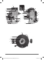 2
2
-
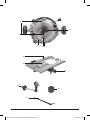 3
3
-
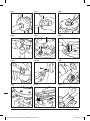 4
4
-
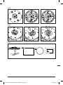 5
5
-
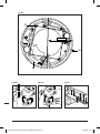 6
6
-
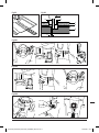 7
7
-
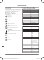 8
8
-
 9
9
-
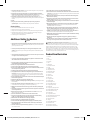 10
10
-
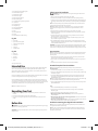 11
11
-
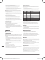 12
12
-
 13
13
-
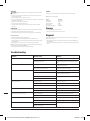 14
14
-
 15
15
-
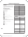 16
16
-
 17
17
-
 18
18
-
 19
19
-
 20
20
-
 21
21
-
 22
22
-
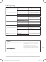 23
23
-
 24
24
-
 25
25
-
 26
26
-
 27
27
-
 28
28
-
 29
29
-
 30
30
-
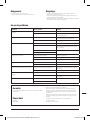 31
31
-
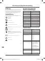 32
32
-
 33
33
-
 34
34
-
 35
35
-
 36
36
-
 37
37
-
 38
38
-
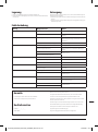 39
39
-
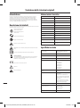 40
40
-
 41
41
-
 42
42
-
 43
43
-
 44
44
-
 45
45
-
 46
46
-
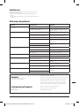 47
47
-
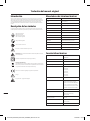 48
48
-
 49
49
-
 50
50
-
 51
51
-
 52
52
-
 53
53
-
 54
54
-
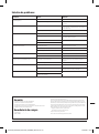 55
55
-
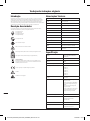 56
56
-
 57
57
-
 58
58
-
 59
59
-
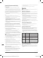 60
60
-
 61
61
-
 62
62
-
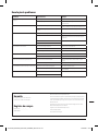 63
63
-
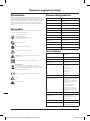 64
64
-
 65
65
-
 66
66
-
 67
67
-
 68
68
-
 69
69
-
 70
70
-
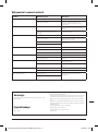 71
71
-
 72
72
-
 73
73
-
 74
74
-
 75
75
-
 76
76
-
 77
77
-
 78
78
-
 79
79
-
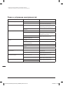 80
80
-
 81
81
-
 82
82
-
 83
83
-
 84
84


Triton TRA002KIT Instrukcja obsługi
- Kategoria
- Elektronarzędzia
- Typ
- Instrukcja obsługi
w innych językach
- español: Triton TRA002KIT Manual de usuario
- italiano: Triton TRA002KIT Manuale utente
- Deutsch: Triton TRA002KIT Benutzerhandbuch
- português: Triton TRA002KIT Manual do usuário
- français: Triton TRA002KIT Manuel utilisateur
- Nederlands: Triton TRA002KIT Handleiding
Powiązane dokumenty
Inne dokumenty
-
Ferm PRM1015 Instrukcja obsługi
-
Parkside POF 1200 A1 Operation And Safety Notes Translation Of Original Operation Manual
-
Parkside POF1300 Instrukcja obsługi
-
Sparky Group X 2015CE Instrukcja obsługi
-
-
Ferm PRM1011 Instrukcja obsługi
-
Parkside POF 1200 D3 Translation Of The Original Instructions