
SENSE ELITE 2022-05-09
2900 5470
SVENSKA
INSTALLATIONSANVISNING
ENGLISH
INSTALLATION GUIDE
DEUTSCH
INSTALLATIONSANLEITUNG
FRANÇAIS
NOTICE D’INSTALLATION
РУССКИЙ
ИНСТРУКЦИИ ПО УСТАНОВКЕ
POLSKI
INSTRUKCJA INSTALACJI
NEDERLANDS
INSTALLATIEHANDLEIDING
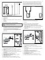
A

IPX4
SVENSKA - INNEHÅLL
FÖRE INSTALLATION .........................................................2
INSTALLATION ....................................................................4
ANSLUTNING/KOPPLINGSSCHEMA ................................7
EGENKONTROLL AV INSTALLATION ...............................9
ENGLISH - TABLE OF CONTENTS
PRIOR TO INSTALLATION ............................................... 11
INSTALLATION ..................................................................13
CONNECTION/WIRING DIAGRAM ...................................16
SELF-INSPECTION OF THE INSTALLATION ..................18
DEUTSCH - INHALTSVERZEICHNIS
VOR DER INSTALLATION ................................................20
INSTALLATION ..................................................................22
ANSCHLUSSDIAGRAMM/SCHALTPLAN ........................ 25
EIGENINSPEKTION DER INSTALLATION .......................27
FRANÇAIS - SOMMAIRE
AVANT L’INSTALLATION ..................................................29
INSTALLATION ..................................................................31
SCHÉMA DE RACCORDEMENT/BRANCHEMENT .........34
AUTOCONTRÔLE DE L’INSTALLATION .........................36
РУССКИЙ - СОДЕРЖАНИЕ
ПЕРЕД УСТАНОВКОЙ .....................................................38
УСТАНОВКА .....................................................................40
ПОДКЛЮЧЕНИЕ/СХЕМА СОЕДИНЕНИЙ ......................43
САМОСТОЯТЕЛЬНАЯ ПРОВЕРКА ПРАВИЛЬНОСТИ
УСТАНОВКИ .....................................................................43
POLSKI - SPIS TREŚCI
PRZED MONTAŻEM ..........................................................47
INSTALACJA .....................................................................49
SCHEMAT POŁĄCZEŃ I OKABLOWANIA .......................52
PRZEGLĄD INSTALACJI WE WŁASNYM ZAKRESIE ....54
NEDERLANDS - INHOUD
VOORAFGAANDE AAN DE INSTALLATIE ......................56
INSTALLATIE .....................................................................58
AANSLUIT- EN BEDRADINGSSCHEMA ..........................61
ZELFINSPECTIE VAN DE INSTALLATIE .........................63
Måttuppgifter / vikt..........................................................64
Dimensions / weight.......................................................64
Abmessungen / Gewicht................................................64
Indication des dimensions / poids................................64
Размеры / вес.................................................................64
Wymiarowanie / waga.....................................................64
Aangegeven maten / gewicht.........................................64

1
VARNING!
• Felaktig ventilation eller felaktig placering av aggregat kan under vissa betingelser medföra torrdestillation
med risk för brand!
• Otillräcklig isolering av basturummet kan medföra risk för brand!
• Användning av felaktiga material i basturum, som t.ex. spånplatta, gips o.s.v. kan medföra risk för brand!
• Anslutning av aggregatet skall utföras av behörig elektriker enligt gällande föreskrifter!
• Det är ej tillåtet att montera mer än ett bastuaggregat i samma basturum.
• Utluftsventil skall ej mynna ut i det fria. Detta kan påverka aggregatets temperaturskydd då ventilationsrikt-
ningen kan bli omvänd.
• Eventuellt tomrum ovanför bastutaket får ej vara helt inneslutet, utan måste ha minst ett ventilhål på sam-
ma vägg som bastudörren!
• Se alltid till att aggregatet ansluts med rätt huvudspänning/fasspänning!
• Personer med nedsatt fysisk eller psykisk prestationsförmåga, handikapp, eller liten erfarenhet av eller
kunskap om utrustningens användning (t.ex. barn), får endast använda utrustningen under uppsikt av eller
enligt instruktioner från den person som ansvarar för deras säkerhet!
• Beröring av aggregatets ovandel ger brännskador. Tylö rekommenderar att aggregatskydd alltid används.
• Se till att barn inte leker nära aggregatet!
• Bastubad kan vara påfrestande för personer med svag hälsa. Rådgör med läkare.
• Doftessenser etc kan innebära risk för antändning om de hälls outspädda på stenmagasinet.
• Övertäckning av bastuaggregatet medför brandfara.
• Doftessenser etc. kan innebära risk för antändning om de hälls outspädda på stenmagasinet!
• Om man häller vatten i luftfuktaren efter att den är upphettad fi nns det en stor risk att kokande vatten
skvätter ut mot de badande. Det är inte lämpligt att stå framför eller sitta på laven framför aggregat om vat-
ten hälls luftfuktaren, då hett vatten kan skvätta ut ganska kraftfullt.
• Om stenmagasinet sätts igen med grus och småsten kan rörelementen ta skada till följd av överhettning då
luftgenomströmningen inte blir tillräcklig.
• Basturummet skall inspekteras innan en omstart av aggregatet sker
• Basturummet skall inspekteras innan aggregatet ställs i standby-läge för en fördröjd start
• Termostatgivaren måste installeras så att den inte påverkas av inkommande luft
• Bastudörren är utrustad med en brytare som bryter standby-läget om dörren öppnas när standby-läget är
aktiverat via fjärstyrningssystemet
• Möjlighet för allpolig frånkoppling måste fi nnas I den fasta installationen enligt gällande regler
• Denna apparat kan användas av barn som är 8 år och äldre och av personer med nedsatt kapacitet, förut-
satt att de har fått instruktioner och/eller tillsyn när det gäller säker användning av apparaten och att de
förstår de potentiella riskerna
• Låt inte barn leka med produkten
• Barn får inte utföra rengöring eller underhåll av apparaten utan uppsikt

2
FÖRE INSTALLATION
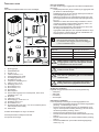
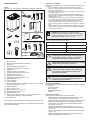
Delar
Kontrollera att följande delar fi nns med i emballaget:
Fig 1: Bastuaggregatets/manöverpanelens delar
1. Bastuaggregat
2. Örtskål/luftfuktare
3. Konsol x 4 st
4. Låsskruv B8x9,5 x 1 st
5. Varningsetikett på tio språk
6. Överkopplingsbleck x 3 st
7. Konsolskruvar x 4 st
8. Tempsensor, kabellängd 4 m
9. Clips TC (3-5) x 10 st
10. Plastplugg 25x5 x 2 st
11. Skruv B6x25 x 2 st
12. Skruv B4x6,5 x1 st
13. Sensorkåpa
14. Manöverpanel
15. Kabel mellan aggregat och manöverpanel, RJ10 4P4C,
kabellängd 5 m x 1 st
16. Buntband
17. Clips C3x5 x 10 st
18. Modularplugg 4, 4/4RJ10 x 2 st
19. Plastplugg 25x5 x 3 st
20. Skruv B6x25 x 3 st
21. Skyddsslang Ø14x150 mm x 3 st, för RJ10 kablar (sensor,
manöverpanel, dörrkontakt)
22. Dörrkontakt
Kontakta återförsäljare om någon del saknas.
Manöverpanel Elite medföljer Sense Elite.
Se separata anvisningar.
Verktyg för installation
Följande verktyg/material behövs för montering/anslutning:
• vattenpass,
• skiftnyckel,
• borrmaskin,
• skruvmejslar.
Planering av installation
Innan du påbörjar monteringen av bastuaggregatet bör du:
• Planera bastuaggregatets placering (se Avsnittet Aggregatets
placering - normalmontage, sidan 3).
• Planera manöverpanelens placering (se medföljande anvis-
ning för manöverpanel för tillåten placering). Se även Avsnit-
tet Manöverpanelens placering, sidan 4.
• Planera sensorns placering (se Fig 3 samt Fig 5).
• Placera inluftsventilen (se Avsnittet Inluftsventilens placering,
sidan 4).
• Placera utluftsventilen (se Avsnittet Utluftsventilens placering,
sidan 4).
• Planera elinstallationen (se Avsnittet Anslutning/kopplings-
chema, Fig. 17).
NOTERA! En murad stenvägg utan värmeisolering
ökar föruppvärmningstiden. Varje kvadratmeter
av putsad tak- eller väggyta motsvarar ett tillägg på
1,2–2 m³ till bastuns volym.
2
7
5
6
1
3
4
8
910 11
12
13
17
15
14
18 19 20
16
Elite
21
22
FARA! Felaktig ventilation eller felaktig placering
av aggregat kan under vissa betingelser medföra
torrdestillation med risk för brand!
FARA! Otillräcklig isolering av basturummet kan
medföra risk för brand!
FARA! Användning av felaktiga material i bastu-
rum, som t.ex. spånplatta, gips o.s.v. kan medföra
risk för brand!
FARA! Anslutning av aggregatet skall utföras av
behörig elektriker enligt gällande föreskrifter!
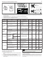
Tabell 1: Eff ekt och bastuvolym
Eff ekt kW Bastuvolym min/max m³
6,6 4-8
8 6-12
10,5 10-18
Krav för installation
För säker användning av aggregatet, kontrollera att följande krav
tillgodoses:
• Kabel (EKK) eller elrör (Fk) för anslutning av aggregatet dras
på utsidan av värmeisoleringen.
• Kabeldragningarna ska vara korrekt utförda (se Avsnittet An-
slutning/kopplingsschema, Fig. 17).
• Säkringens storlek (A) och strömkabelns storlek (mm²) ska
passa aggregatet (se Avsnittet Anslutning/kopplingsschema,
Fig. 17).
• Ventilation av bastu ska utföras enligt instruktioner i denna
manual (se Avsnittet Inluftsventilens placering, sidan 4, Av-
snittet Utluftsventilens placering, sidan 4).
• Placering av bastuaggregat, manöverpanel och sensor ska
ske enligt instruktionerna i denna manual.
• Aggregatets eff ekt (kW) ska vara anpassat till bastuns volym
(m³) (se Tabell 1). Minimivolymen får inte underskridas och
maximivolymen får inte överskridas.

3
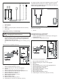
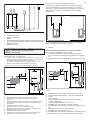
Aggregatets placering - nischmontage
För att placera bastuaggregatet i nisch:
1. Placera aggregatet på säkert avstånd till golv, sidovägg och
inredning (se Fig 5).
2. Placera sensorn enligt bilden (se Fig 5).
1
3
2
45
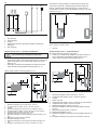
Fig 2: Schematisk översikt av installation
1. Bastuaggregat
2. Manöverpanel
3. Sensor
4. Extern on/off -brytare (tillval, dörrkontakt krävs för funktion)
5. Dörrkontakt
Aggregatets placering - normalmontage
FARA! Det är ej tillåtet att montera mer än ett
bastuaggregat i samma basturum.
Placera bastuaggregatet:
• på samma vägg som dörren (endast i undantagsfall på sido-
väggen, men då mycket nära dörrväggen). Aggregatet kan
också placeras i nisch (se Fig 5).
• på säkert avstånd till golvet, sidoväggar och inredning (se Fig
3).
Placera sensorn enligt bilden (se Fig 3).
Om väggen på vilken sensorn ska installeras är gjord av mycket
värmeabsorberande material (t.ex. betong, tegel m.m.) eller om
väggen är gjort av härdats glas, kan sensorn placeras i taket med
avstånd från aggregatet enligt Fig 4.
1
4
8
11
10
12
2
6
5
9
7
3
3
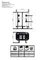
Fig 3: Placering av bastuaggregatet - normalmontage
1. Minsta avstånd till sidovägg: 110 mm
2. Sensorns placering alt 1: 300 mm från aggregat
3. Sensorn
4. Minsta avstånd bakre vägg (med ben): 95 mm
5. Sensorns placering alt 2: 300 mm från aggregatets front
6. Sensorns placering: 150 mm från tak
7. Minsta avstånd till tak: 1030 mm
8. Minsta avstånd till inredning: 100 mm
9. Minsta takhöjd: 1900 mm
10. Minsta avstånd: 20 mm
11. Minsta avstånd till inredning: 30 mm
12. Avstånd till golv: 100-270 mm, (med ben: 100 mm)
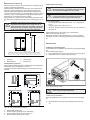
Fig 5: Placering av bastuaggregat - nischmontage
1. Minsta avstånd till sidovägg: 110 mm
2. Sensorns placering alt 1: 300 mm från aggregat
3. Sensorn
4. Max 1000 mm
5. Sensorns placering alt 2: 300 mm från aggregatets front
6. Sensorns placering: 150 mm från tak
7. Minsta avstånd till tak: 1030 mm
8. Minsta avstånd till inredning: 100 mm
9. Minsta takhöjd: 1900 mm
10. Minsta avstånd: 20 mm
11. Minsta avstånd till inredning: 30 mm
12. Avstånd till golv: 100-270 mm, (med ben: 100 mm)
Fig 4: Takmontering av sensorn på aggregatets mittlinje både
framifrån och från sidan
1. 300 mm
1 1
8
11
10
12
4
1 1 9
7
2
6
3
5
3

4
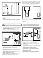
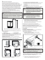
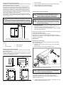
Inluftsventilens placering
Placera inluftsventilen rakt genom väggen mitt under aggregatet.
Ventilstorlek för en familjebastu ca. 125 cm².
Dörrens luftcirkulation skall samarbeta med varmluften från ag-
gregatet.
Manöverpanelens placering
Placering utanför basturum rekommenderas om möjligt på grund
av lägre omgivningstemperaturer.
Manöverpanelen är tillåten att placeras inne i ett Tylö basturum
alternativt egenbyggt basturum vars ventilation är utförd och
fungerar enligt Tylö förespråkad ventilation (självdragsprincip).
Läs avsnitten Inluftventilens och Utluftsventilens placering i denna
anvisning, sidan 4. Manöverpanelen skall alltid placeras utanför
basturummet om inte dessa krav är uppfyllda.
Vid placering inne i basturummet så ska manöverpanelen monte-
ras med hänsyn till säkerhetsavstånd och monteringshöjd, se Fig
6.
Fig 7: In- och utluftsventilens placering
1. Inluftsventilens placering.
2. Utluftsventilens placering genom bastuvägg.
3. Utluftsventilens placering genom tomrum.
4. Utluftsventilens placering via trumma.
Fig 6: Säkerhetsavstånd/monteringshöjd manöverpanel
1. Aggregat 3. Max 800 mm
2. Manöverpanel 4. Min 300 mm
Utluftsventilens placering
Placera utluftsventilen:
• med maximalt avstånd till inluftsventilen, t.ex. i diagonal (se
Fig 7).
• högt på väggen eller i taket (se Fig 7).
• så att den utmynnar till det utrymme som dörr och inluftsven-
tilmynnar till.
Utluftsventilen ska ha samma area som inluftsventilen.
Tillse att utluftsventilen är öppen.
Mekaniskt ventilation rekommenderas ej p.g.a. risk för felaktig
luftväxling som kan påverka aggregatets temperaturskydd nega-
tivt.
1 2
34
FARA! Utluftsventil skall ej mynna ut i det fria.
Detta kan påverka aggregatets temperaturskydd
då ventilationsriktningen kan bli omvänd.
FARA! Eventuellt tomrum ovanför bastutaket får
ej vara helt inneslutet, utan måste ha minst ett
ventilhål på samma vägg som bastudörren!
2
4
3
1
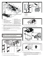
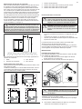
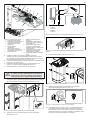
Fig 8: Öppna/stänga luckan
Aggregatet ansluts med vanlig standardledning (Fk eller EKK),
godkänd för fast installation.
Eventuell enkelledare (Fk) skyddas i elrör (VP) fram till aggrega-
tet.
3. Anslut elkabeln (se Fig 9) enligt kopplingsschema (se Fig.
17).
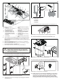
INSTALLATION
Installation av bastuaggregat
Förberedelserna för installation görs enklast när aggregatet ligger
ner.
För att installera aggregatet:
1. Lägg aggregatet med fronten upp. Montera vredet (se Fig 8).
2. Lossa skruvarna och öppna luckan (se Fig 8).
VARNING! Se alltid till att aggregatet ansluts med
rätt huvudspänning/fasspänning!
VARNING! Vid felaktigt utförd ventilation riskerar
monterad manöverpanel inne i basturum att ut-
sättas för högre temperatur än tillåten och kan bli
deformerad eller gå sönder. Omgivningstempera-
tur för manöverpanel får aldrig överstiga 80°C.
1
0

5
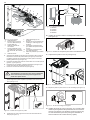
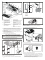
Fig 12: Montering av doftbehållare/luftfuktare
11. Häng upp aggregatet på skruvarna se Fig 13.
8. Lossa de två första skruvarna på aggretatets baksida och
skruva fast en av de fyra konsolerna. Upprepa proceduren
tills alla konsolerna sitter på plats se Fig 10.
Fig 13: Häng upp aggregatet
12. Lås aggregatet på plats med låsskruven se Fig 14.
Fig 14: Konsolens låsskruv
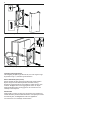
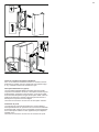
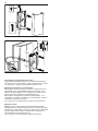
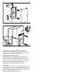
13. Montera sensorn på väggen se Fig 15. Termistorledningen
kan även dras igenom väggen. Täta eventuella hål
i väggen bakom sensorn, se Fig 16. Termistorledningen kan
förlängas utanför bastun med svagströmsledning
(2-ledare).
Fig 11: Måttsättning
1. 262 mm
2. 270 mm
3. 532 mm
4. 206 mm
10. Montera örtskål/luftfuktare (se Fig 12).
OBS! Om alla baksidans skruvar lossas samtidigt
kan baksidans plåt lossna. Montera därför de fyra
konsolerna en i taget på aggregatet.
Fig 10: Montera konsolerna på aggregatet
9. Placera konsolskruvarna enligt måttsättning se Fig 11.
2
4
3
1
4. Dra kablar för manöverpanel och temperatursensor genom
kabelgenomföringarna (se Fig. 9). Anslut manöverpanelens
kabel i en av de fyra RS485-kontakterna (position 6-9) (se Fig
18).
5. Anslut sensorns kabel till NTC-kontakten på kretskortet
(position 1) (se Fig. 18).
6. Anslut eventuell kabel till belysning, se Fig 9, till enligt kopp-
lingsschema Fig 17.
7. Stäng luckan och skruva i skruvarna (se Fig 8).
2
8
4
5
7
6
9
1
10
3
11
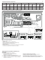
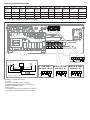
Fig 9: Kretskortet
1. Elkabel
2. Plint för inkoppling av elkabel
3. Kabelgenomföring (x5)
4. Manöverpanelens kabel
5. Modularkontakter för inkoppling
av manöverpanel, sensor etc.
6. Sensorns kabel
7. Eventuell belysningskabel
8. Plint för eventuell inkoppling
av belysning + IR
9. Dragavlastning för kablar till
modularkontakter (x2)
10. Dragavlastning för elkabel
11. Skyddsslang för RJ10 kablar

6
Fig 15: Montering av sensorn
Fig 16: Ledningsdragning genom vägg.
Min. Ø13mm
16mm
20mm
12mm
Ovanliga spänningar/fas-tal
Vid inkoppling till spänningar eller fas-tal, som inte anges i kopp-
lingsschema Fig 17, kontakta Tylö kundservice.
Extern ON/OFF-brytare (tillval)
Extern ON/OFF-brytare placeras på valfri plats utanför bastun.
Brytare fungerar med både impuls eller konstant slutning,
kretskortet i aggregat känner automatiskt av vilken slutning som
används. Möjlighet fi nns att se aggregatets status och fel på
dörrkontakt ifall brytare har inbyggd led. Se instruktioner som
medföljer externbrytaren.
Dörrkontakt
Dörrkontakt är ett krav för att kunna använda Pure-panelens för-
valstid eller Elite-panelens kalenderfunktion samt fjärrstyra bastun
via externbrytare, mobilapplikation eller PC-applikation.
Se instruktioner som medföljer dörrkontakten.

7
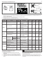
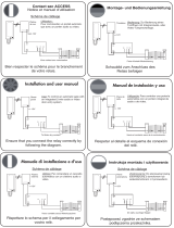
Fig 17: Kopplingsschema
1. Aggregat
2. Sensor (ansluts till NTC pos 1)
3. Manöverpanel (ansluts till pos 6-9)
4. Externbrytare (tillval)
5. Dörrkontakt
6. Belysning / plint för inkoppling av belysning / IR
7. Plint för inkoppling av elkabel
1
654
32
7
RJ10 4P4C
3 x 0.75 mm2
RJ10 4P4C
RJ10 4P4C
RJ10 4P4C
Control panel Elite - max 30m
*
*
6,6-8,0 kW
200-240 V 1N~/2~
6,6-8,0-10,5 kW
200-230 V 3~
6,6-8,0-10,5 kW
400-415 V 3N~
6
BGGIIB
Max 100W
200-240 V~
INFRA
Max 2,2kW
200-240 V~
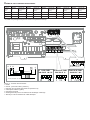
ANSLUTNING/KOPPLINGSSCHEMA
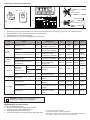
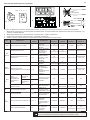
TAB 400-415 V 3N~ (C) 200-208 V 3~ (B) 230 V 3~ (B) 200-208 V~ (A) * 230-240 V~ (A) *
Eff ekt
kW
Strömstyr-
ka amp
Lednings-
area mm²
Strömstyr-
ka amp
Lednings-
area mm²
Strömstyr-
ka amp
Lednings-
area mm²
Strömstyr-
ka amp
Lednings-
area mm²
Strömstyr-
ka amp
Lednings-
area mm²
6,6 10 1,5 19 4 17 4 33 10 29 10
8 12 2,5 23 6 20 4 40 16 35 10
10,5 16 2,5 32 10 28 10 - - - -
* 10,5 kW är inte godkänd för enfas i europa

8
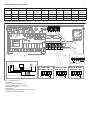
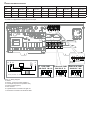
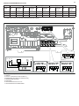
Light
Distribution Box
Control Panel(s) Temp Sensor Door Switch
Pos. 6-9
External Switch
12
6789
34 5
On
2ႇ
CTS
123456
Sauna
Factory settings
Dipswitch
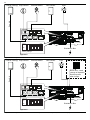
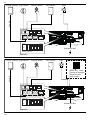
Fig. 18. Schematisk installation Sense Elite
Fig. 19. Schematisk installation Sense Elite med Infra. DIP-switcharna ställs om enligt bilden.
Light
Distribution Box
Control Panel(s) Temp Sensor Door Switch
Pos. 6-9
External Switch
12
6789
34 5
On
2ႇ
CTS
123456
Sauna IR
Dipswitch
Infra
Note! Infra - need
change of dipswitch.
Restart system
after change.

9
EGENKONTROLL AV INSTALLATION
För att kontrollera installationen:
1. Slå på huvudspänning till aggregat från elcentral.
2. Försäkra dig om att manöverpanelen lyser .
3. Starta aggregatet (se Bruksanvisning).
4. Kontrollera att alla de tre rörelementen går igång (blir röda).
Denna bruksanvisning bör sparas!
Vid eventuella problem, kontakta inköpsstället.
© Eftertryck, helt eller delvis, är förbjudet utan Tylös skriftliga tillstånd. Rätt
till ändringar i material, konstruktion och design förbehålls.
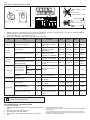
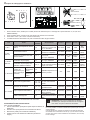
Beskrivning av kablage/modularkontakter
NOTERA! Vid ändring av modularkablage, t. ex.
förkortning av ledning, krävs en crimptång.
1234Pin:
1234Pin:
1
2
3
4
12
6789
34 5
Cable
Solid conductor
Cable
Stranded conductor
Max. Ø3,6mm
OK!
Fig. 20 Modularplugg/modularkontakt, reläkort "high" och ledare fl ertrådig
1. Modularplugg RJ10, används till kabel (max. kabelarea för kontaktering av modularplugg: 0,14-0,20 mm² / AWG26-AWG24)
2. Modularjack RJ10, sittter monterad på reläkort och manöverpanel
3. Reläkort "high" (Pos. 6-9 vita anslutningar)
4. Kabel/ledare som ansluts till modularplugg skall vara fl ertrådig
Tabell 3: Beskrivning av reläkortets anslutningar
Pos Enhet Använd
pin Anmärkning Pin1 Pin 2 Pin 3 Pin 4
1 - NTC Tempsensor i rum 2, 3 10kΩ. Kan även kopplas
in på pos 4 - SEC/NTC. Not use 10kΩ10kΩNot use
2 - EXT
SWITCH
Externbrytare 3, 4 Start/stopp av drift. Kon-
stant eller impulsslutning. Not use Not use Switch Switch
Externbrytare med led-indikering 2, 3, 4
Start/stopp av drift.
12VDC max 40mA.
Tylö artikel nr: 90908048
Not use Led GND Switch Switch /
Led 12V
3 - DOOR
SWITCH
Dörrkontakt (NO) 3, 4 Tylö artikel nr: 90908035 Not use Not use Switch Switch
Dörrkontakt (NO) med extern
larm-indikering 2, 3, 4
12VDC max 40mA. Krävs
extern kopplingsbox,
saluförs inte.
Not use Led GND Switch Switch /
Led 12V
4 - SEC/NTC
Kombinerad
tempsensor/
tempskydd i rum
Tempsensor
10kΩ2, 3 Används endast till vissa
produkter. Sec 10kΩ10kΩSec
Tempskydd
130°C 1, 4
Adapter för aktivering av drift-
status 1, 4 Steam Commercial Sec Not use Not use Sec
5 - ADD-ON Extra reläkort 1, 2, 3, 4,
5, 6, 7, 8
Obs! Ej för nätverksan-
slutning.
6-9 - RS485
Manöverpaneler 1, 2, 3, 4 Tylö Elite och Pure manö-
verpanel. A (RS485) B (RS485) 12V GND
Temp/fuktsensor % 1, 2, 3, 4
Combiaggregat med
Elite manöverpanel och
Tylarium.
A (RS485) B (RS485) 12V GND
Synkkabel A/B 1, 2
Multisteam och Tylarium.
Primär och sekundär
enhet.
A (RS485) B (RS485) Not use Not use

10
WARNING!
• Poor ventilation or heater positioning may lead to dry distillation, posing a fi re risk under certain circum-
stances!
• Insuffi cient insulation of the sauna cabin may pose a fi re risk!
• Use of the wrong materials in the sauna cabin, such as particle board, drywall, etc., may pose a fi re risk!
• The heater must be connected by a qualifi ed electrician pursuant to applicable regulations!
• No more than one heater may be installed in the same sauna cabin.
• The air exhaust vent must not lead outdoors. This could cause the ventilation direction to be reversed,
which may negatively aff ect the heater temperature cut-out.
• Any gap above the sauna ceiling should not be sealed without leaving at least one vent hole on the same
wall as the sauna door!
• Always check that the heater is connected to the correct main/phase voltage!
• Anyone with a mental or physical disability or little experience or knowledge of how to use the equipment
(e.g. children) must be instructed or supervised by someone responsible for their safety.
• Touching the upper parts of the heater may cause burn injuries. Tylö recommends always using the hea-
ter screen.
• Never allow children to play near the heater!
• Saunas are not recommended for people in poor health. Please consult a doctor.
• Fragrant essences and similar products may ignite, if poured directly onto the stones.
• Covering the heater may cause a fi re.
• Fragrant essences etc. may ignite if poured directly onto the stones.
• Do not pour water into the fragrance holder once it has been heated up, as this can cause boiling water to
splash on the sauna occupants. Do not stand or sit in front of the heater while water is being poured into
the fragrance holder, as hot water can spray out suddenly.
• If the stone compartment fi lls up with gravel and small stones, the tubular element can be damaged as a
result of overheating, as air fl ow will be insuffi cient.
• The sauna room or cabin is to be inspected before either restarting the timer or by switching on the appli-
ance by a separate remote-control system
• The sauna room or cabin is to be inspected before setting the appliance to a standby mode for a delayed
start
• Thermostat sensors have to be installed so that they are not infl uenced by incoming air
• The door of the sauna room or cabin is fi tted with an interlock such that the stand-by mode setting for
remote operation is disabled if the sauna door or cabin door is opened when the stand-by mode setting
for remote operation is set
• Means for full pole disconnection must be incorporated in the fi xed wiring in accordance with the wiring
rules
• This appliance can be used by children aged from 8 years and above and persons with reduced physical,
sensory or mental capabilities or lack of experience and knowledge if they have been given supervision
or instruction concerning use of the appliance in a safe way and understand the hazards involved
• Children shall not play with the appliance
• Cleaning and user maintenance shall not be made by children without supervision

11
PRIOR TO INSTALLATION
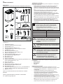
Parts
Check that the following parts are included in the packaging:
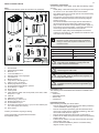
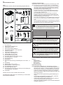
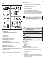
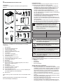
Figure 1: Sauna heater/control panel parts
1. Sauna heater
2. Herb bowl/air humidifi er
3. Brackets x 4
4. Lock screw B8x9.5 x 1
5. Warning sticker in ten languages
6. Connectors x 3
7. Bracket screws x 4
8. Temp.sensor, cable length 4 m
9. Clips TC (3-5) x 10 pieces
10. Plastic plugs 25x5 x 2 pieces
11. Screws RXS/A2 PHIL B6x25 x 2 pieces
12. Screw B4x6,5 x 1 piece
13. Sensor cover
14. Control panel
15. Cable between heater and control panel, RJ10 4P4C, cable
length 5 m x 1 pce
16. Cable tie
17. Clips C3x5 x 10 pieces
18. Modular plug 4, 4/4RJ10 x 2
19. Plastic plugs 25x5 x 3 pcs
20. Screws B6x25 x 3 pcs
21. Protection hose Ø14x150 mm x 3 pcs, for RJ10 cables (sen-
sor, control panel, door switch)
22. Door contact
Contact your dealer if anything is missing.
Control panel Elite is supplied with Sense Elite.
See separate guides.
Installation tools
The following tools and materials are needed for installation and
connection:
• water level,
• adjustable spanner,
• electric drill,
• screwdrivers.
Installation planning
Before starting to install your sauna heater:
• Plan the sauna heater positioning (see the Heater positioning
- normal installation section, page 12).
• Plan the control panel positioning (see the attached instruc-
tions for the control panel for allowable positioning). See also
the Control Panel section on page 13.
• Plan the sensor positioning (see Figure 3 and Figure 5).
• Position the air intake vent (see the Air intake vent positioning
section, page 13).
• Position the air exhaust vent (see the Air exhaust vent positi-
oning section, page 13).
• Plan the electrical installation (see the Connection/wiring
diagram section, Figure 17).
NOTE! A brick wall without heat insulation increases
the warm-up time. Each square meter of plastered
ceiling or wall surface equals an additional 1.2–2 m³
of sauna volume.
2
7
5
6
1
3
4
8
910 11
12
13
17
15
14
18 19 20
16
Elite
21
22
DANGER! Poor ventilation or heater positioning
may lead to dry distillation, posing a fi re risk
under certain circumstances!
DANGER! Insuffi cient insulation of the sauna
cabin may pose a fi re risk!
DANGER! Use of the wrong materials in the
sauna cabin, such as particle board, drywall, etc.,
may pose a fi re risk!
DANGER! The heater must be connected by a
qualifi ed electrician pursuant to applicable regu-
lations!
Table 1: Output and sauna volume
Output kW Sauna volume min./max. m³
6,6 4-8
8 6-12
10,5 10-18
Installation requirements
To ensure safe use of the heater, check that the following criteria
are met:
• Cable (EKK) or electrical ducting (Fk) for connecting the hea-
ter must be run on the outside of the heat insulation.
• The cables must be run correctly (see the Connection/wiring
diagram section, Figure 17).
• The fuse size (A) and the power cable size (mm²) must be
suitable for the heater (see the Connection/wiring diagram
section, Figure 17).
• The sauna ventilation must comply with the instructions in
this manual (see the Air intake valve positioning section,
page 13, the Air exhaust valve positioning section, page 13).
• The position of the sauna heater, control panel and sensors
must comply with the instructions in this manual.
• The heater's output (kW) must be adapted to the sauna's
volume (m³) (see Table 1). The minimum and maximum volu-
mes must not be exceeded.

12
Positioning the heater - recess installation
To position the sauna heater in a recess:
1. Position the heater at a safe distance from the fl oor, side
walls and interior fi ttings (see Figure 5).
2. Position the sensor according the picture (see Figure 5).
1
3
2
45
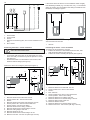
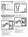
Figure 2: Schematic diagram of installation
1. Sauna heater
2. Control panel
3. Sensor
4. External on/off switch (option, door contact needed for func-
tion)
5. Door contact
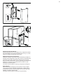
Positioning the heater - normal installation
DANGER! No more than one heater may be instal-
led in the same sauna cabin.
Position the sauna heater:
• on the same wall as the door (or the side wall if very close
to the door wall). The heater may also be placed in a recess
(see Figure 5).
• Position the heater at a safe distance from the fl oor, side
walls and interior fi ttings (see Figure 3).
Position the sensor according the picture (see Figure 3).
If the wall on which the sensor is to be installed is made of highly
heat-absorbing material (e.g. concrete, brick, etc.), or of hardened
glass, the sensor may be installed in the ceiling at a distance from
the heater, according to Figure 4.
1
4
8
11
10
12
2
6
5
9
7
3
3
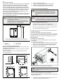
Figure 3: Positioning the heater - normal installation
1. Minimum distance from side wall: 110 mm
2. Sensor position alt 1: 300 mm from heater
3. Sensor
4. Minimum distance from back wall (with legs): 95 mm
5. Sensor position alt 2: 300 mm from heater front
6. Sensor position: 150 mm from ceiling
7. Minimum distance from ceiling: 1030 mm
8. Minimum distance from interior fi ttings: 100 mm
9. Minimum ceiling height: 1900 mm
10. Minimum distance: 20 mm
11. Minimum distance from interior fi ttings: 30 mm
12. Distance from fl oor: 100-270 mm (with legs: 100 mm)
Figure 5: Positioning the heater - recess installation
1. Minimum distance from side wall: 110 mm
2. Sensor position alt 1: 300 mm from heater
3. Sensor
4. Max. 1000 mm
5. Sensor position alt 2: 300 mm from heater front
6. Sensor position: 150 mm from ceiling
7. Minimum distance from ceiling: 1030 mm
8. Minimum distance from interior fi ttings: 100 mm
9. Minimum ceiling height: 1900 mm
10. Minimum distance: 20 mm
11. Minimum distance from interior fi ttings: 30 mm
12. Distance from fl oor: 100-270 mm (with legs: 100 mm)
Figure 4: Sensor installation on ceiling on centreline of heater as
seen from the front and side
1. 300 mm
1 1
8
11
10
12
4
1 1 9
7
2
6
3
5
3

13
Positioning the inlet vent
Install the inlet vent straight through the wall under the centreline
of the heater.
Vent size for a family sauna approx. 125 cm².
The air circulation from the door must concord with the hot air
circulation from the heater.
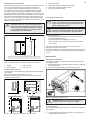
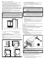
Figure 7: Positioning the air intake and exhaust vents
1. Inlet vent position.
2. Outlet vent position through the sauna wall.
3. Outlet vent position through the cavity.
4. Outlet vent position via duct.
Positioning the outlet vent
Position the outlet vent
• at the maximum possible distance from the air intake vent,
e.g. diagonally (see Figure 7).
• high on the wall or in the ceiling (see Figure 7).
• so that it vents into the space that the door and air intake
vent open into.
The outlet vent must have the same area as the inlet vent.
Ensure that the outlet vent is open.
Mechanical ventilation is not recommended due to the risk of poor
air exchange, which can negatively aff ect the heater temperature
cut-out.
1 2
34
DANGER! The air exhaust vent must not lead out-
doors. This could cause the ventilation direction
to be reversed, which may negatively aff ect the
heater temperature cut-out.
DANGER! Any gap above the sauna ceiling
should not be sealed without leaving at least one
vent hole on the same wall as the sauna door!
Figure 6: Safety distance / installation height, control panel
1. Heater 3. Max. 800 mm
2. Control panel 4. Min. 300 mm
2
4
3
1
Figure 8: Opening/closing the cover
Connect the heater using standard wiring (Fk or EKK) approved
for fi xed installation.
Any single wires (Fk) must be protected in electrical conduits (VP)
to the heater.
3. Connect the electrical cable (see Figure 9) according to the
wiring diagram (see Figure 17).
INSTALLATION
Sauna heater installation
It is easiest to prepare for installation with the heater lying down.
To install the heater:
1. Lay the heater down with the front facing upwards. Install the
knob (see Figure 8).
2. Undo the screws and open the cover (see Figure 8).
WARNING! Always check that the heater is con-
nected to the correct main/phase voltage!
1
0
Placement of the control panel
Where possible, placement of the control panel outside the sauna
room is recommended due to lower ambient temperatures.
The control panel may be placed inside a Tylö sauna room or
a self-built sauna room with correct ventilation which operates
according to Tylö-recommended ventilation (natural ventilation
principle). Read the sections titled, Positioning the intake vent and
Positioning the outlet vent in these instructions. The control panel
must always be placed outside the sauna cabin if these require-
ments are not met. If installing the control panel inside the sauna
cabin, it should be positioned with regard to safety distances and
installation height, see Fig 6.
WARNING! With incorrect ventilation, a control
panel fi tted inside the sauna cabin may be expo-
sed to excessive temperatures, which can cause
the control panel to become deformed or defecti-
ve. The ambient temperature around the control
panel should never exceed 80°C.

14
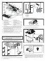
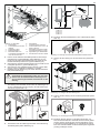
Figure 12: Fitting the fragrance holder/air humidifi er
11. Hang the heater on the screws see Fig. 13.
8. Unscrew the fi rst two screws on the back of the heater and
screw one of the four brackets into place. Repeat the proce-
dure until all of the brackets are fi tted see Fig. 10.
Figure 13: Hang the heater up.
12. Lock the heater into place with the lock screw see Fig. 14.
Figure 14: Lock screw for bracket
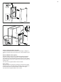
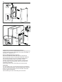
13. Install the sensor on the wall see Fig 15. The thermistor wire
may also be passed through the wall. Seal any holes in the
wall behind the sensor, see Figure 16. The thermistor wire
may be extended outside the sauna using low voltage wire
(2-lead).
Figure 11: Dimensioning
1. 262 mm
2. 270 mm
3. 532 mm
4. 206 mm
10. Fit herb bowl/air humidifi er (see Fig. 12).
NB: If all the screws on the back are unscrewed
simultaneously, the back plate may come loose.
For this reason, attach the four brackets to the
heater one at a time.
Figure 10: Attaching the brackets to the heater
9. Position the bracket screws according to the specifi ed dimen-
sioning see Fig. 11.
2
4
3
1
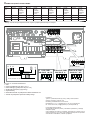
4. Run the cables for the control panel and the temperature
sensor through the cable grommets (see Figure 9). Connect
the control panel cable to one of the four RS485 contacts
(positions 6-9) (see Figure 18).
5. Connect the sensor cable to the NTC contact on the circuit
board (position 1) (see Figure 18).
6. Connect the light cable (if relevant), see Figure 9, according
to the wiring diagram Figure 17.
7. Close the cover and tighten the screws (see Figure 8).
2
8
4
5
7
6
9
1
10
3
11
Figure 9: Circuit board
1. Electrical cable
2. Terminal for connection of
electrical cable
3. Cable grommet (x5)
4. Control panel cable
5. Modular contacts for
connection of control panel,
sensor etc.
6. Sensor cable
7. Light cable (if relevant)
8. Terminal for connection of light +
IR (if relevant)
9. Strain relief connector for cables
to modular contacts (x2)
10. Strain relief connector for electri-
cal cable
11. Protection hose for RJ10 cables

15
Unusual voltages/numbers of phases
Contact Tylö Customer Service before connecting to voltages or
numbers of phases that are not listed in the wiring diagram Figure
17.
Figure 15: Installing the sensor
Figure 16: Wiring through the wall.
Min. Ø13mm
16mm
20mm
12mm
External ON/OFF switch (option)
External ON/OFF switch can be installed anywhere outside the
sauna. The switch works for impulse or constant deactivation.
The heater circuit automatically recognises which is used. Heater
status and faults on the door contact can be seen if the switch has
a built-in LED.
See instructions supplied with the external switch.
Door contact
The door contact is necessary to be able to use the Pure panel’s
preselected time or the Elite panel’s calendar function, plus remo-
te control the sauna via external switch, mobile or PC apps.
See instructions supplied with the door contact.

16
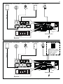
Figure 17: Wiring diagram
1. Heater
2. Sensor - (connect to NTC position 1)
3. Control panel (connect to positions 6-9)
4. External switch (option)
5. Door contact
6. Light/terminal for connection of light / IR
7. Terminal for connection of electrical cable
1
654
32
7
RJ10 4P4C
3 x 0.75 mm2
RJ10 4P4C
RJ10 4P4C
RJ10 4P4C
Control panel Elite - max 30m
*
*
6,6-8,0 kW
200-240 V 1N~/2~
6,6-8,0-10,5 kW
200-230 V 3~
6,6-8,0-10,5 kW
400-415 V 3N~
6
BGGIIB
Max 100W
200-240 V~
INFRA
Max 2,2kW
200-240 V~
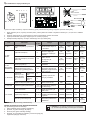
CONNECTION/WIRING DIAGRAM
TAB 400-415 V 3N~ (C) 200-208 V 3~ (B) 230 V 3~ (B) 200-208 V~ (A) * 230-240 V~ (A) *
Output
kW
Amperage
amp
Conductor
area mm²
Amperage
amp
Conductor
area mm²
Amperage
amp
Conductor
area mm²
Amperage
amp
Conductor
area mm²
Amperage
amp
Conductor
area mm²
6,6 10 1,5 19 4 17 4 33 10 29 10
8 12 2,5 23 6 20 4 40 16 35 10
10,5 16 2,5 32 10 28 10 - - - -
* 10,5 kW is not approved for singel phase in Europe

17
Light
Distribution Box
Control Panel(s) Temp Sensor Door Switch
Pos. 6-9
External Switch
12
6789
34 5
On
2ႇ
CTS
123456
Sauna
Factory settings
Dipswitch
Figure 18. Schematic diagram of installation Sense Elite
Figure 19. Schematic diagram of installation, Sense Elite with Infra. Reset the DIP switches as pictured.
Light
Distribution Box
Control Panel(s) Temp Sensor Door Switch
Pos. 6-9
External Switch
12
6789
34 5
On
2ႇ
CTS
123456
Sauna IR
Dipswitch
Infra
Note! Infra - need
change of dipswitch.
Restart system
after change.

18
SELF-INSPECTION OF THE INSTALLATION
To check the installation:
1. Switch on the mains supply to the heater from the distribution
board.
2. Check that the control panel lights up.
3. Start the heater (see User Guide).
4. Check that all three tubular elements start to heat up (go
red).
Please keep these instructions!.
In the event of problems, please contact the retailer where you purchased
the equipment.
© This publication many not be reproduced, in part or in whole, without
the written permission of Tylö. Tylö reserves the right to make changes to
materials, construction and design.
Description of cabling/modular contacts
NOTE! Crimp pliers are needed if changing modular
cabling, e.g. shortening wires.
1234Pin:
1234Pin:
1
2
3
4
12
6789
34 5
Cable
Solid conductor
Cable
Stranded conductor
Max. Ø3,6mm
OK!
Fig 20. Modular plug/modular contactor, relay board "high" and multithreaded lead
1. Modular plug RJ10, used with cable (max. cable cross-section for connection of modular plug: 0.14-0.20 mm² / AWG26-AWG24)
2. Modular jack RJ10, connected to relay board and control panel
3. Relay board "high" (Pos. 6-9 white connectors)
4. Cable/lead connected to the modular plug must be multithreaded
Table 3: Description of relay board connections
Pos Unit Use pin Comment Pin1 Pin 2 Pin 3 Pin 4
1 - NTC Temp. sensor in the room 2, 3
10kΩ. May also be con-
nected at Pos 4 - SEC/
NTC.
Not use 10kΩ10kΩNot use
2 - EXT
SWITCH
External switch 3, 4
Start/stop operation.
Constant or impulse
deactivation.
Not use Not use Switch Switch
External switch with LED indica-
tion 2, 3, 4
Start/stop operation.
12VDC max. 40mA.
Tylö Item no.: 90908048
Not use Led GND Switch Switch /
Led 12V
3 - DOOR
SWITCH
Door contact (NO) 3, 4 Tylö Item no.: 90908035 Not use Not use Switch Switch
Door contact (NO) with an exter-
nal alarm indication 2, 3, 4
12VDC max. 40mA.
External junction box, not
for sale.
Not use Led GND Switch Switch /
Led 12V
4 - SEC/NTC
Combined tempe-
rature sensor/cut-
out in the room
Temp. sensor
10kΩ2, 3
Only used for certain
products. Sec 10kΩ10kΩSec
Temperatu-
re cut-out
130°C
1, 4
Adapter for activation of opera-
ting status 1, 4 Steam Commercial Sec Not use Not use Sec
5 - ADD-ON Extra relay board 1, 2, 3, 4,
5, 6, 7, 8
Note: Not for network
connection.
6-9 - RS485
Control panels 1, 2, 3, 4 Tylö Elite and Pure con-
trol panels. A (RS485) B (RS485) 12V GND
Temp./Humidity sensor % 1, 2, 3, 4
Combi heater with Elite
control panel and Tyla-
rium.
A (RS485) B (RS485) 12V GND
Synchronisation cable A/B 1, 2
Multisteam and Tylarium.
Primary and secondary
units.
A (RS485) B (RS485) Not use Not use
Strona się ładuje...
Strona się ładuje...
Strona się ładuje...
Strona się ładuje...
Strona się ładuje...
Strona się ładuje...
Strona się ładuje...
Strona się ładuje...
Strona się ładuje...
Strona się ładuje...
Strona się ładuje...
Strona się ładuje...
Strona się ładuje...
Strona się ładuje...
Strona się ładuje...
Strona się ładuje...
Strona się ładuje...
Strona się ładuje...
Strona się ładuje...
Strona się ładuje...
Strona się ładuje...
Strona się ładuje...
Strona się ładuje...
Strona się ładuje...
Strona się ładuje...
Strona się ładuje...
Strona się ładuje...
Strona się ładuje...
Strona się ładuje...
Strona się ładuje...
Strona się ładuje...
Strona się ładuje...
Strona się ładuje...
Strona się ładuje...
Strona się ładuje...
Strona się ładuje...
Strona się ładuje...
Strona się ładuje...
Strona się ładuje...
Strona się ładuje...
Strona się ładuje...
Strona się ładuje...
Strona się ładuje...
Strona się ładuje...
Strona się ładuje...
Strona się ładuje...
-
 1
1
-
 2
2
-
 3
3
-
 4
4
-
 5
5
-
 6
6
-
 7
7
-
 8
8
-
 9
9
-
 10
10
-
 11
11
-
 12
12
-
 13
13
-
 14
14
-
 15
15
-
 16
16
-
 17
17
-
 18
18
-
 19
19
-
 20
20
-
 21
21
-
 22
22
-
 23
23
-
 24
24
-
 25
25
-
 26
26
-
 27
27
-
 28
28
-
 29
29
-
 30
30
-
 31
31
-
 32
32
-
 33
33
-
 34
34
-
 35
35
-
 36
36
-
 37
37
-
 38
38
-
 39
39
-
 40
40
-
 41
41
-
 42
42
-
 43
43
-
 44
44
-
 45
45
-
 46
46
-
 47
47
-
 48
48
-
 49
49
-
 50
50
-
 51
51
-
 52
52
-
 53
53
-
 54
54
-
 55
55
-
 56
56
-
 57
57
-
 58
58
-
 59
59
-
 60
60
-
 61
61
-
 62
62
-
 63
63
-
 64
64
-
 65
65
-
 66
66


w innych językach
- Deutsch: Tylö TY-61001034 Installationsanleitung
- français: Tylö TY-61001034 Guide d'installation
- Nederlands: Tylö TY-61001034 Installatie gids
Powiązane artykuły
-
Tylö SENSE PURE Installation#hs_cos_wrapper_module_170083095099528 .icon-style--link .g-module-macros-icon { padding-left:8px; } #hs_cos_wrapper_module_170083095099528 .icon-style--link .g-module-macros-icon svg { fill:#C65622; } Instrukcja obsługi
-
-
-
-
-
-
-
-
-
Inne dokumenty
-
 SCS Sentinel AAA0009 Instrukcja obsługi
-
Sentiotec PRO-C2 Sauna Control Unit PRO C Instrukcja obsługi
-
 HUUM 4744103010332 Instrukcja instalacji
-
 HUUM Cliff Electric Sauna Heater Instrukcja obsługi
-
 HUUM 4744103010332 Instrukcja instalacji
-
HARVIA SW45 Instructions For Installation And Use Manual
-
 HUUM CORE ELECTRIC SAUNA HEATER Instrukcja obsługi
-
HUUM DROP Electric Sauna Heater Instrukcja obsługi
-
Narvitech NM, MINEX, NS Sauna Heater Instrukcja instalacji
-


