Bradford White 50A-15-3-103Q-AA Instrukcja instalacji
- Typ
- Instrukcja instalacji

238-45837-00J REV 5/18
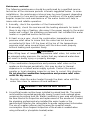
ASME COMMERCIAL ELECTRIC WATER HEATER
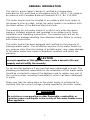
THE WARRANTY ON THIS WATER HEATER IS IN EFFECT ONLY WHEN
THE WATER HEATER IS INSTALLED AND OPERATED IN ACCORDANCE
WITH LOCAL CODES AND THESE INSTRUCTIONS. THE
MANUFACTURER OF THIS WATER HEATER WILL NOT BE LIABLE FOR
ANY DAMAGE RESULTING FROM FAILURE TO COMPLY WITH THESE
INSTRUCTIONS. READ THESE INSTRUCTIONS THOROUGHLY BEFORE
STARTING.
For your comfort, safety and convenience, it is recommended this
water heater be installed and serviced by a plumbing professional.
INSTALLATION & OPERATING
INSTRUCTION MANUAL
A Spanish language version of these instructions is available by
contacting the company listed on the rating plate.
La versión espãnola de estas instructiones se puede obtener al
escribible a la fábrica cuyo nombre aparece en la placa de
especificaciones.

2
CONGRATULATIONS!
You have just purchased one of the finest water heaters
on the market
today!
This installation, operation and instruction manual will explain in
detail the installation and maintenance of your new ASME Commercial
Electric Water Heater. We strongly recommend that you contact a
plumbing professional for the installation of this water heater.
We require that you carefully read this manual, as well as the
enclosed warranty, and refer to it when questions arise. If you have
any specific questions concerning your warranty, please consult the
plumbing professional from whom your water heater was purchased.
For your records we recommend that you write the model, serial
number and installation date of your water heater in the maintenance
section in the back of this manual.
This manual should be kept with the water heater.
TABLE OF CONTENTS
General Information ................................................... 3
Installation ............................................................... 4
Locating The Water Heater ............................................. 4
Water Connections ........................................................ 6
Electrical Connections .................................................... 13
Amperage Chart .......................................................... 14
GPH Recovery Capacities ............................................. 14
General Operation ..................................................... 15
Thermostat Adjustment .................................................. 15
Maintenance ............................................................. 16
Servicing Guide ......................................................... 19

3
GENERAL INFORMATION
This electric water heater’s design is certified by Underwriters
Laboratories (UL) and listed in accordance with UL 1453. C-UL listed in
accordance with Canadian National Standard C22.2, No. 110-M90.
This water heater must be installed in accordance with local codes. In
the absence of local codes, install this water heater in accordance with
the latest edition of the National Electrical Code.
The warranty for this water heater is in effect only when the water
heater is installed, adjusted, and operated in accordance with these
Installation and Operating Instructions. The manufacturer will not be
held liable for damage resulting from alteration and/or failure to comply
with these instructions.
This water heater has been designed and certified for the purpose of
heating potable water. The installation and use of this water heater for
any purpose other than the heating of potable water, may cause damage
to the water heater and create a hazardous condition and nullify the
warranty.
Do not use this appliance if any part has been submerged in water. The
plumbing professional responsible for the installation of this water heater
should be contacted to inspect the appliance and to replace any part of
the control system, including thermostat(s), which has been submerged
in water.
Make sure that the rating plate on the water heater is referenced for
certainty that the correct voltage is being supplied to the water heater.
CAUTION
Incorrect operation of this appliance may create a hazard to life and
property and will nullify the warranty.
DANGER
Do not store or use gasoline or other flammable, combustible, or
corrosive vapors and liquids in the vicinity of this water heater or any
other appliance.

4
General Information continued-
A sacrificial anode(s) is used to extend tank life. Removal of any anode,
except for inspection and/or replacement, will nullify the warranty. In areas
where water is unusually active, an odor may occur at the hot water faucet
due to a reaction between the sacrificial anode and impurities in the water. If
this should happen, an alternative anode(s) may be purchased from the
supplier that installed this water heater. This will minimize the odor while
protecting the tank. Additionally, the water heater should be flushed with
appropriate dissolvers to eliminate any bacteria.
WARNING
This product contains one or more chemicals known to the State of
California to cause cancer, birth defects, or reproductive harm.
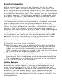
INSTALLATION
Locating The Water Heater
This water heater MUST not be installed in any location where gasoline
or flammable vapors are likely to be present, unless the installation is
such to eliminate the probable ignition of gasoline or flammable
vapors.
The location where this water heater is to be installed is of utmost
importance. Before installing this water heater, consult the installation section
of these instructions. After reading these installation and operating
instructions, select a location for the water heater where the floor is level and
is easily accessible to a power supply and water connections. It is
recommended that the water heater be located near the center of greatest
hot water usage to prevent heat loss through the pipes. DO NOT locate the
water heater where water lines could be subjected to freezing
temperatures. Locate the water heater so that access panels, drain
valves, and clean-out openings are accessible.
IMPORTANT
Before proceeding, please inspect the water heater and its components for
possible damage. DO NOT install any damaged components. If damage is
evident, please contact the supplier where the water heater was purchased or
the manufacturer listed on the rating plate for replacement parts.
WARNING
Water heaters are heat producing appliances. To avoid damage or injury,
there shall be no materials stored against the water heater and proper care
shall be taken to avoid unnecessary contact (especially by children) with the
water heater. UNDER NO CIRCUMSTANCES SHALL FLAMMABLE
MATERIALS, SUCH AS GASOLINE OR PAINT THINNER BE USED OR
STORED IN THE VICINITY OF THIS WATER HEATER OR ANY
LOCATION FROM WHICH FUMES COULD REACH THE WATER
HEATER.

5
Locating The Water Heater continued-
Water heater corrosion and component failure can be caused by the
heating and breakdown of airborne chemical vapors. Examples of some
typical compounds that are potentially corrosive are: spray can
propellants, cleaning solvents, refrigerator and air conditioning
refrigerants, swimming pool chemicals, calcium or sodium chloride,
waxes and process chemicals. These materials are corrosive at very low
concentration levels with little or no odor to reveal their presence.
NOTE: DAMAGE TO THE WATER HEATER CAUSED BY EXPOSURE TO
CORROSIVE VAPORS IS NOT COVERED BY THE WARRANTY. DO NOT
OPERATE THE WATER HEATER IF EXPOSURE HAS OR WILL OCCUR.
DO NOT STORE ANY POTENTIALLY CORROSIVE COMPOUNDS IN THE
VICINITY OF THE WATER HEATER.
This water heater must be located in an area where leakage from the
tank, water line connections, and the combination temperature and
pressure relief valve will not result in damage to the area adjacent to the
water heater or to lower floors of the structure. When such locations
cannot be avoided, a suitable drain pan must be installed under the
water heater. The drain pan must have a minimum length and width of
at least 4 in. (10.2 cm) greater than the diameter of the water heater.
The drain pan, as described above, can be purchased from your
plumbing professional. The drain pan must be piped to an adequate
drain. The piping must be pitched for proper drainage.
CLEARANCES
1. Minimum clearance to combustible material is 0 inches for the Top,
Sides, Front, and Rear of this water heater. However, it is
recommended that at least 18 inches (45.7 cm) from the Top, and
24 inches (61 cm) from the Front. Clearance for servicing may be
reduced down to minimum clearance to combustible material, but
service time and effort may be greatly increased.
2. Increase distances to provide clearances for servicing.
This water heater MUST be installed indoors out of the wind and
weather.
To comply with NSF requirements this water heater is to be:
a) Sealed to the floor with sealant, in a smooth and easily cleanable
way, or
b) Installed with an optional leg kit that includes legs and/or extensions
that provide a minimum clearance of 6’’ beneath the water heater.
Note: For California installation this water heater must be braced,
anchored, or strapped to avoid falling or moving during an earthquake.
See instructions for correct installation procedures. Instructions may be
obtained from the DSA Headquarters Office: 1102 Q Street, Suite 5100,
Sacramento, CA 95811.

6
Water Connections
Note: Before proceeding with the installation, close the main water
supply valve.
After shutting the main water supply valve, open a faucet to relieve the
water line pressure in order to prevent water from leaking out of the
pipes while making the water connections to the water heater. After the
pressure has been relieved, close the faucet. The cold water inlet line
connects to the inlet nipple at the base of the water heater. The hot
water outlet line connects to the nipple on top of the water heater. The
fittings at the cold water inlet and hot water outlet are dielectric
waterway fittings with tapered male threads. Make the proper plumbing
connections between the water heater and the plumbing system in the
structure. Install a manual shut-off valve in the cold water supply line.
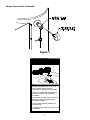
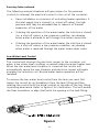
This water heater may be provided with an optional pressure and
temperature gauge. See Figure 1 for proper installation.
If this water heater is installed in a closed water supply system, such as
one having a back-flow preventer in the cold water supply, provisions
must be made to control thermal expansion. DO NOT operate this water
heater in a closed system without a provision for controlling thermal
expansion. Contact your water supplier or local plumbing inspector
regarding how thermal expansion can be controlled.
After installation of the water lines, open the main water supply valve
and fill the water heater. While the water heater is filling, open several
hot water faucets to allow air to escape from the water system. When a
steady stream of water flows through the faucets, close the faucets and
inspect all water connections for possible leaks. NEVER OPERATE THE
WATER HEATER WITHOUT FIRST BEING CERTAIN IT IS COMPLETELY
FILLED WITH WATER.
CAUTION
If sweat fittings are to be used, DO NOT apply heat to the nipples on
top of the water heater. Sweat the tubing to the adapter before fitting
the adapter to the water connections. It is imperative that heat is not
applied to the nipples containing a plastic liner.
IMPORTANT
FAILURE TO INSTALL AND MAINTAIN A NEW, LISTED
TEMPERATURE-PRESSURE RELIEF VALVE WILL RELEASE THE
MANUFACTURER FROM ANY CLAIM WHICH MIGHT RESULT FROM
EXCESSIVE TEMPERATURE AND PRESSURES.

7
Water Connections continued-
WARNING
For protection against excessive temperatures and pressure, install
temperature and pressure protective equipment required by local
codes, but not less than a combination temperature and pressure relief
valve certified by a nationally recognized testing laboratory that
maintains periodic inspection of production of listed equipment or
materials, as meeting the Requirements for Relief Valves and
Automatic Gas Shutoff Devices for Hot Water Supply Systems, ANSI
Z21.22, and the Standard CAN1-4.4 Temperature, Pressure,
Temperature and Pressure Relief Valves and Vacuum Relief Valves.
The combination temperature and pressure relief valve shall be marked
with a maximum set pressure, not to exceed the maximum working
pressure of the water heater. The combination temperature and
pressure relief valve shall also have an hourly rated temperature steam
BTU discharge capacity not less than the hourly input rating of the
water heater.
Install the combination temperature and pressure relief valve into the
opening on the water heater, which is provided for this purpose.
Note: Some models may already be equipped or supplied with a
combination temperature and pressure relief valves. Verify that this
combination temperature and pressure relief valve complies with local
codes. If the combination temperature and pressure relief valve does
not comply with local codes, replace it with one that does. Follow the
installation instructions provided on this page.
Install a discharge line so that water discharged from the combination
temperature and pressure relief valve will exit within six (6) inches
(15.3 cm) above, or any distance below the structural floor and at a
location where dischargers cannot contact any live electrical part. This
discharge line is to be installed complete drainage of both the
temperature and pressure relief valve and the discharge line can occur.
The discharge opening must not be subjected to blockage or freezing.
DO NOT thread, plug or cap the discharge line. It is recommended that
a minimum of four (4) inches (10.2 cm) be provided on the side of the
water heater for servicing and maintenance of the combination
temperature and pressure relief valve.
Do not place a valve between the combination temperature and
pressure relief valve and the tank.

8
Water Connections continued-
This water heater can deliver scalding temperature water at any faucet
in the system. Be careful whenever using hot water to avoid scalding
injury. Certain appliances, such as dishwashers and automatic clothes
washers, may require increased temperature water. By setting the
thermostat on this water heater to obtain the increased temperature
water required by these appliances, the potential for scald injury is
increased. To protect against injury, install an anti-scald tempering valve
in the water system. This valve will reduce the point of discharge water
temperature by mixing cold and hot water in branch supply lines. Anti-
sealed tempering valves can be obtained from your local plumbing
supplier. Please consult a plumbing professional.
WARNING
Hydrogen gas can be produced in the hot water system served by this
water heater when there has been no usage for a long period of time
(generally two weeks or more). Hydrogen gas is extremely flammable.
Therefore, to reduce the risk of injury under these conditions, it is
recommended that the hot water faucet be opened for several
minutes at the kitchen sink before using any electrical appliance
connected to the hot water system. If hydrogen is present, there will
probably be an unusual sound, such as air escaping through the pipe,
as the water begins to flow. There should be no smoking or open
flame near the faucet at the time it is open.
CAUTION
INCREASING THE THERMOSTAT SETTING ABOVE THE PRESET
TEMPERATURE MAY CAUSE SEVERE BURNS AND CONSUME
EXCESSIVE ENERGY. HOTTER WATER INCREASES THE RISK OF
SCALD INJURY.

9
Water Connections continued-
Figure 1

10
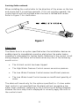
Water Connections continued-
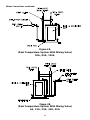
Figure 2A
(Dual Temperature System With Mixing Valve)
50A, 80A, 120A
Figure 2B
(Dual Temperature System With Mixing Valve)
6A, 12A, 20A, 30A, 40A

11
Water Connections continued-
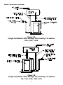
Figure 3A
(Single Installation With Storage Tank Gravity Circulation)
50A, 80A, 120A
Figure 3B
(Single Installation With Storage Tank Gravity Circulation)
6A, 12A, 20A, 30A, 40A

12
Water Connections continued-
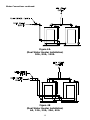
Figure 4A
(Dual Water Heater Installation)
50A, 80A, 120A
Figure 4B
(Dual Water Heater Installation)
6A, 12A, 20A, 30A, 40A

13
Electrical Connections
Before any electrical connections are attempted, be sure the water
heater is full of water and that the manual shut-off valve in the cold
water supply line is open. Heating elements, which have been energized
for a very short period of time, can be damaged (burned-out) if they are
not completely immersed in water. This warranty does not cover burned-
out heating elements. Check the rating plate and wiring diagram before
proceeding. This electric water heater was manufactured and wired in
accordance with the Underwriters Laboratories testing approvals
requirements. The temperature-limiting device is of the manual reset,
trip-free type and has been factory installed to interrupt all ungrounded
power supply conductors in the event of thermostat failure. The
plumbing supplier in your area ordered this water heater wired at the
factory to comply with existing area codes, but local utility codes may
require or allow other circuitry. Consult your local power company to
determine the correct electrical hook-up in order to meet local utility and
building codes and in order to obtain the most economical rates. All
electrical connections to elements, thermostats, contactors, fuses
(certain models), and transformer have been made at the factory. DO
NOT alter any of the internal wiring. Wiring connections may loosen
during shipment. Check all connections for tightness.
To make the wiring connections to a power supply, follow the steps
below.
A) Open the cover door of the control box.
B) Bring the power leads from an adequately fused disconnect switch
(not furnished with the water heater due to varying state and local
codes) and connect to the terminal block. Local ordinances and/or
utility company may require an increase in the gage size of the wiring
for conditions where long wiring lengths exist.
C) This water heater must be properly grounded. A ground lug is
provided within the electrical control box for connection to a properly
sized ground. (See wiring diagram for minimum required ground size.
The wiring diagram is located on the inside door of the control box)
D) Close the cover door of the control box.
Heating Elements
To replace heating elements, disconnect power to the water heater,
drain tank and replace element. To remove a heating element, use a
screw type element wrench (1 1/2’’ or 2 3/8’’) available from most
supply houses. Do not over-tighten the new element, as this will cause
distortion in the new element gasket. Once the element has been
replaced, follow the instructions ‘‘To Fill The Water Heater’’. It is
imperative that the water heater is full before power is restored to the
heating elements.

14
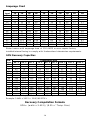
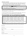
Amperage Chart
kW
208V
240V
277V
380V
415V
480V
415V
Input
1Ø
3Ø
1Ø
3Ø
1Ø
3Ø
3Ø
1Ø
3Ø
3Ø
3
15
-
13
-
11
-
-
7
-
-
6
29
17
25
14
22
9
8
12
8
8
9
43
25
38
22
32
14
13
19
13
13
12
58
33
50
29
43
19
17
25
17
17
13.5
65
38
56
32
49
21
19
28
19
19
15
72
42
63
36
54
23
21
31
21
21
18
87
50
75
43
65
28
25
38
25
25
24
115
67
100
58
87
37
34
50
34
34
27
130
75
113
65
97
41
38
56
38
38
30
144
83
125
72
108
46
42
63
42
42
36
173
100
150
87
130
55
50
75
50
50
45
216
125
188
108
162
69
63
94
63
63
54
260
150
225
130
195
83
75
113
75
75
81
390
225
338
195
293
123
113
169
98
78
Water heaters with amperage draw of 120 AMPS or more require factory
installed internal fusing to comply with Underwriters Laboratories requirements.
GPH Recovery Capacities
kW
Temperature Rise
Input
40°F
50°F
60°F
70°F
80°F
90°F
100°F
120°F
140°F
3
31
25
21
18
16
14
13
11
9
6
62
50
41
35
31
28
25
21
18
9
93
74
62
53
47
41
37
31
27
12
124
99
83
71
62
55
50
41
35
13.5
140
112
93
80
70
62
56
47
40
15
155
125
103
89
78
69
62
52
44
18
186
149
124
106
93
83
74
62
53
24
248
199
164
142
124
110
99
83
71
27
279
223
186
160
140
124
112
93
80
30
310
248
207
177
155
138
124
103
89
36
372
298
248
213
186
165
149
124
106
45
465
372
310
266
233
207
186
155
133
54
558
447
372
319
279
248
223
186
160
81
837
671
558
479
419
372
335
279
240
Multiply kW input by 3,412 to determine BTU input:
Example: 54kW x 3412 = 184,248 BTU’s
Recovery Computation Formula
GPH= (watts x 3.412) / (8.25 x °Temp. Rise)

15
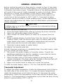
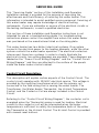
GENERAL OPERATION
Before closing the switch to allow electric current to flow to the water
heater, make certain that the water heater is full of water and that the
cold water inlet valve is open. Complete failure of the heating elements
will result if they are not totally immersed in water at all times. When
the switch is closed, the operation of this electric water heater is
automatic. The temperature control knob located on the side on the
control box is factory preset to 120° F (49°C). Care must be taken
whenever using hot water to avoid scalding injury. Certain appliances
require high temperature hot water (such as dishwashers and automatic
clothes washers).
TO FILL THE WATER HEATER
1. Close the water heater drain valve by turning the knob clockwise.
2. Open the cold water supply shut-off valve.
3. Open several hot water faucets to allow air to escape from the
system.
4. When a steady stream of water flows from the faucets, the water
heater is filled. Close the faucets and check for water leaks at the
water heater drain valve, combination temperature and pressure
relief valve and the hot and cold water connections.
5. Reconnect power supply to water heater.
TO DRAIN THE WATER HEATER
Should it become necessary to completely drain the water heater, make
sure you follow the steps below:
1. Disconnect the power supply to the water heater. Consult the
plumbing professional or electric company in your area for service.
2. Close the cold water supply shut-off valve.
3. Open the drain valve on the water heater by turning the knob
counter-clockwise. The drain valve has threads on the end that will
allow connection of a standard hose coupling.
4. Open a hot water faucet to allow air to enter the system.
To refill the water heater, refer to ‘‘TO FILL THE WATER HEATER.’’
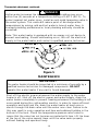
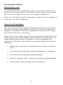
Thermostat Adjustment
To adjust the water temperature, locate the temperature control dial on
the right side of the control box. To increase the water temperature,
rotate the temperature control dial clockwise. To decrease the water
temperature, rotate the temperature control dial counterclockwise (see
Figure 5). The thermostat(s) or temperature control dial has been factory
preset to approximately 120° F (49°C).
CAUTION
Scalding may occur within five (5) seconds at a temperature setting
of 140°F (60°C).

16
Thermostat adjustment continued-
Figure 5
MAINTENANCE
Shut off the electric power whenever the water supply to the water
heater is off. Shut off the electric power and water supply, drain the
water heater completely to prevent freezing whenever the building is left
unoccupied during the cold weather months. In order to insure efficient
operation and long tank life, drain the water heater at least once a
month through the drain valve until the water runs clear. Failure to do
this may result in noisy operation and lime and sediment buildup in the
bottom of the tank. Check the temperature-pressure relief valve to
insure that the valve has not become encrusted with lime. Lift the lever
at the top of the valve several times until the valve seats properly
without leaking and operates freely.
DANGER
Hotter water increases the risk of scald injury. Scalding may occur
within five (5) seconds at a temperature setting of 140°F (60°C). To
protect against hot water injury, install an anti-scald tempering valve in
the water system. This valve will reduce point of discharge water
temperatures by mixing cold and hot water in branch water lines. A
licensed plumbing professional or local plumbing authority should be
consulted.
Note: This water heater is equipped with an energy cut out device to
prevent overheating. Should overheating occur, turn off the electrical
supply to the water heater and contact a qualified service technician.
IMPORTANT
The water heater should be inspected at a minimum of annually by a
qualified service technician for damaged components. DO NOT
operate this water heater if any part is found damaged.

17
Maintenance continued-
The following maintenance should be performed by a qualified service
technician at the minimum periodic intervals suggested below. In some
installations, the maintenance interval may be more frequent depending
on the amount of use and the operating conditions of the water heater.
Regular inspection and maintenance of the water heater will help to
insure safe and reliable operation.
1. Annually, check the operation of the thermostat(s).
2. Bi-annually, check the seal around the heating elements for leaks. If
there is any sign of leaking, disconnect the power supply to the water
heater and contact the plumbing professional that installed this water
heater or a qualified service technician.
3. At least once a year, check the combination temperature and
pressure relief valve to insure that the valve has not become
encrusted with lime. Lift the lever at the top of the temperature-
pressure relief valve several times until the valve seats properly
without leaking and operates freely.
4. If the combination temperature and pressure relief valve on the
appliance discharges periodically, this may be due to thermal
expansion in a closed water supply system. Contact the water
supplier or local plumbing inspector on how to correct this situation.
Do not plug the combination temperature and pressure relief valve
outlet for any reason.
5. Monthly, drain the water heater through the drain valve until the
water runs clear to remove silt and sediment.
6. A sacrificial anode rod has been installed to extend tank life. The anode
rod should be inspected periodically (every 2 years) and replaced when
necessary to prolong tank life. Water conditions in your area will influence
the time interval for inspection and replacement of the anode rod. Contact
the plumbing professional who installed the water heater or the
manufacturer listed on the rating plate for anode replacement information.
The use of a water softener may increase the speed of anode
consumption. More frequent inspection of the anode is needed when
using softened (or phosphate treated) water.
WARNING
When lifting lever of temperature-pressure relief valve, hot water will
be released under pressure. Be certain that any released water does
not result in bodily injury or property damage.
WARNING! THIS WATER MAY BE HOT.

18
Maintenance continued-
7. If this water heater is equipped with fuses, before removing any fuse,
disconnect the all power to the water heater. Open the control box
door and replace fuses according to the size indicated on the wiring
diagram affixed to the inside of the control box door.
Contact your local plumbing supplier or plumbing professional for
replacement parts or contact the company at the address displayed on
the rating plate of the water heater.
For faster and better service, please provide the part name, model, and
serial number(s) of the water heater(s) when ordering parts.
READ THE WARRANTY FOR A FULL EXPLANATION OF THE LENGTH
OF TIME THAT PARTS AND THE WATER HEATER ARE WARRANTED.
Complete the following information and retain for future reference:
Model No:_____________________________________________________
Serial No:______________________________________________________
Service Phone
Days: ______________________Nights:_____________________________
Address:______________________________________________________
Supplier:______________________________________________________
Supplier Phone No:______________________________________________
CAUTION
FOR YOUR SAFETY, DO NOT ATTEMPT TO REPAIR THERMOSTAT(S),
HEATING ELEMENTS, OR ELECTRICAL WIRING. REFER SUCH REPAIRS
TO A QUALIFIED SERVICE TECHNICIAN.
Manufactured under one or more of the following U.S. Patents: 5,277,171;
5,341,770; 5,372,185; 5,485,879; 5,574,822; 5,596,952; 5,660,165;
5,682,666; 5,761,379; 5,943,984; 5,954,492; 5,988,117; 6,056,542;
6,142,216; 6,442,178; 6,684,821; 6,935,280; 7,063,132; 7,063,133;
7,007,748; 7,270,087; 7,334,419; 7,337,517; 7,409,925; 7,458,341;
7,559,293; 7,621,238; 7,634,976; 7,650,859; 7,665,210; 7,665,211;
7,699,026; 7,866,168; 7,900,589; 7,971,560; 7,992,526 8,082,888;
8,146,772; Other U.S. and Foreign patent applications pending. Current
Canadian Patents: 2,092,105; 2,107,012; 2,108,186; 2,112,515; 2,143,031;
2,239,007; 2,262,174; 2,314,845; 2,409,271; 2,476,685; 2,504,824;
2,548,958

19
SERVICING GUIDE
This ‘‘Servicing Guide‘‘ section of this Installation and Operation
Installation manual is provided for the purpose of improving the
effectiveness and the efficiency of servicing this water heater. This
information is intended to assist qualified service personnel. Servicing of
this water heater may require knowledge of electrical testing
instruments. If you are unfamiliar or unsure of the electrical circuits or
the testing instruments, consult a qualified electrician.
This section of these Installation and Operation Instructions is not
intended for use as a troubleshooting guide. For troubleshooting
instructions please contact the supplier from whom this water heater
was purchased or the manufacturer listed on the rating plate.
This water heater has two distinct electrical systems. One system
connects the electrical power to the heating elements, while the other
system controls the water heater operation. The electrical contactors
interconnect these two systems. In order to clearly illustrate the
electrical circuits, two wiring diagrams are provided. These diagrams are
labeled as the ‘‘Power Circuit Wiring Diagram’’ and the ‘‘Control Circuit
Wiring Diagram’’ and they are attached to the surface of the panels
inside the water heater control cabinet.
Control Circuit Description:
This description will explain certain aspects of the Control Circuit. The
control circuit operates with 120VAC electrical service. This voltage is
provided by the multi-tap transformer which has the primary coil
connected to the field wiring that is serving the water heater. The
Transformer, the Water Heater Thermostat, the Hi-Limit Temperature
Control, and the Contactor Coil are always included in the Control
Circuit.
Referring to the ‘‘Control Circuit Wiring Diagram‘‘, the contactor coil is
energized when the Thermostat senses a need for heating. Electrical
current to the contactor coil will be interrupted when the water
temperature is sufficient to satisfy the temperature limits of the either
the Thermostat or the Hi-Limit Control. The Hi-Limit Control is provided
with manual reset buttons.

20
Servicing Guide continued-
Certain other control components are available as ‘‘Optional‘‘. When
these optional components are installed with the water heater, the
control circuit wiring diagram accordingly will include these components.
The optional equipment available from the manufacturer includes the
following:
• High Water Pressure Switch
• Low Water Pressure Switch
• Low Water Level Switch
• Alarm Horn
• Heating Element Sequencers
• Electrical Door Lock
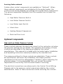
Optional Components
High and Low Water Pressure Controls
These controls interrupt the electrical current to the contactor coil when
the pressure settings are exceeded. The operation and setting of these
controls are described in the manual provided by the control
manufacturer. This manual is included with the water heater Installation
and Operating Instruction manual provided by the manufacturer.
The pressure settings for these controls are adjustable. These controls
are specified for use when the installation has unique pressure
requirements that must be safeguarded. Therefore, before adjusting the
pressure values, it is recommended that you consult the person
responsible for the facility that the water heater is servicing.
The electrical connections are referenced in the Control Circuit Wiring
Diagram and in the pressure control manual provided by the control
manufacturer. Refer to these instructions when servicing the controls.
Strona się ładuje...
Strona się ładuje...
Strona się ładuje...
Strona się ładuje...
-
 1
1
-
 2
2
-
 3
3
-
 4
4
-
 5
5
-
 6
6
-
 7
7
-
 8
8
-
 9
9
-
 10
10
-
 11
11
-
 12
12
-
 13
13
-
 14
14
-
 15
15
-
 16
16
-
 17
17
-
 18
18
-
 19
19
-
 20
20
-
 21
21
-
 22
22
-
 23
23
-
 24
24


