
AKTIVE PA- UND DJ-LAUTSPRECHERBOX
ACTIVE PA AND DJ SPEAKER SYSTEM
ENCEINTE ACTIVE PROFESSIONNELLE DJ
CASSA ACUSTICA ATTIVA PA E DJ
PAK-415 Best.-Nr. 24.3100
BEDIENUNGSANLEITUNG • INSTRUCTION MANUAL • MODE D’EMPLOI • ISTRUZIONI PER L’USO
INSTRUKCJA OBSLUGI • VEILIGHEIDSVOORSCHRIFTEN • CONSEJOS DE SEGURIDAD
SIKKERHEDSOPLYSNINGER • SÄKERHETSFÖRESKRIFTER • TURVALLISUUDESTA

2
Bevor Sie einschalten ...
Wir wünschen Ihnen viel Spaß mit Ihrem neuen Gerät von
„img Stage Line“. Dabei soll Ihnen diese Bedienungsan-
leitung helfen, alle Funktionsmöglichkeiten kennen zu ler-
nen. Die Beachtung der Anleitung vermeidet außerdem
Fehlbedienungen und schützt Sie und Ihr Gerät vor even-
tuellen Schäden durch unsachgemäßen Gebrauch.
Den deutschen Text finden Sie auf den Seiten 4–6.
Before you switch on ...
We wish you much pleasure with your new “img Stage
Line” unit. With these operating instructions you will be
able to get to know all functions of the unit. By following
these instructions false operations will be avoided, and
possible damage to yourself and your unit due to im-
proper use will be prevented.
You will find the English text on the pages 4–6.
D
A
CH
GB
Przed uruchomieniem …
Życzymy zadowolenia z nowego produktu “ img Stage
Line”. Dzięki tej instrukcji obsługi będą Państwo w stanie
poznać wszystkie funkcje tego urządzenia. Stosując się
do instrukcji unikną Państwo błędów i ewentualnego
uszkodzenia urządzenia na skutek nieprawidłowego
użytkowania.
Tekst polski znajduje się na stronach 10–11.
Voordat u inschakelt ...
Wij wensen u veel plezier met uw nieuw toestel van “img
Stage Line”. Lees de veiligheidsvoorschriften, alvorens
het toestel in gebruik te nemen. Door de veiligheidsvoor-
schriften op te volgen zal een slechte werking vermeden
worden, en zal een eventueel letsel aan uzelf en schade
aan uw toestel tengevolge van onzorgvuldig gebruik
worden voorkomen.
U vindt de de veiligheidsvoorschriften op pagina 12.
PL
B
NL
Antes de cualquier instalación
Tenemos de agradecerle el haber adquirido un aparato
“img Stage Line” y le deseamos un agradable uso. Por
favor lee las instrucciones de seguridad antes del uso.
La observación de las instrucciones de seguridad evita
operaciones erróneas y protege Vd. y vuestro aparato
contra todo daño posible por cualquier uso inadecuado.
Las instrucciones de seguridad se encuentran en la
página 12.
Inden De tænder for apparatet ...
Vi ønsker Dem god fornøjelse med Deres nye “img
Stage Line” apparat. Læs oplysningerne for en sikker
brug af apparatet før ibrugtagning. Følg sikkerhedsop-
lysningerne for at undgå forkert betjening og for at be-
skytte Dem og Deres apparat mod skade på grund af for-
kert brug.
Sikkerhedsoplysningerne finder De på side 12.
EDK
Förskrift
Vi önskar dig mycket nöje med din nya enhet från “img
Stage Line”. Läs gärna säkerhetsinstruktionerna innan
du använder enheten. Genom att följa säkerhetsinstruk-
tionerna kan många problem undvikas, vilket annars kan
skada enheten.
Du finner säkerhetsinstruktionerna på sidan 13.
SFIN
Avant toute mise en service ...
Nous vous remercions d’avoir choisi un appareil “img
Stage Line” et vous souhaitons beaucoup de plaisir à
l’utiliser. Cette notice a pour objectif de vous aider à
mieux connaître les multiples facettes de l’appareil. En
outre, en respectant les conseils donnés, vous éviterez
toute mauvaise manipulation de sorte que vous-même et
votre appareil soient protégés de tout dommage.
La version française se trouve pages 7–9.
Prima di accendere ...
Vi auguriamo buon divertimento con il Vostro nuovo
apparecchio “img Stage Line”. Le istruzioni per l’uso Vi
possono aiutare a conoscere tutte le possibili funzioni. E
rispettando quanto spiegato nelle istruzioni, evitate di
commettere degli errori, e così proteggete Voi stessi, ma
anche l’apparecchio, da eventuali rischi per uso impro-
prio.
Il testo italiano lo potete trovare alle pagine 7–9.
F
B
CH
I
Ennen virran kytkemistä ...
Toivomme, että uusi “img Stage Line”-laitteesi tuo sinulle
paljon iloa ja hyötyä. Ole hyvä ja lue käyttöohjeet ennen
laitteen käyttöönottoa. Luettuasi käyttöohjeet voit käyt-
tää laitetta turvallisesti ja vältyt laitteen väärinkäytöltä.
Käyttöohjeet löydät sivulta 13.
wwwwww..iimmggssttaaggeelliinnee..ccoomm

3
GAIN
MIC IN LINE IN
GAIN
010010FREQUENCY
SUBSONIC 120Hz
60Hz
POWER CLIP PROTECT
LOW
–12+12
0
MID
–12+12
0
HIGH
–12+12
0
EQ ON/OFF EQ ON
PARALLEL OUT
LEVEL
010
–∞-40
–∞-60
PAK-415 ACTIVE SPEAKER SYSTEM
WWW.IMGSTAGELINE.COM
230V5/ 50 Hz / 550 VA
T3,15AL
POWER
GND
LIFT
MIC
LINE LOW CUT EQUALIZER
MASTER
GAIN
MIC IN LINE IN
GAIN
010010
FREQUENCY
SUBSONIC 120 Hz
60Hz
POWER CLIP PROTECT
LOW
–12 +12
0
MID
–12 +12
0
HIGH
–12 +12
0
EQ ON/ OFF EQ ON
MIC LINE LOW CUT
PARALLEL OUT
EQUALIZER
LEVEL
010
MASTER
–∞-40
–∞-60
2
3
1 2
3
1
312
WWW.IMGSTAGELINE.COM
PAK-415 ACTIVE SPEAKER SYSTEM
12 3 4 5 6 7 89
10 11 12 13 14 15 16
230 V5/50Hz/550VA
T 3 ,15 A L
GND
LIF T
POWER
17 18 19 20 21

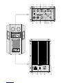
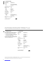
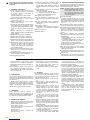
Bitte klappen Sie die Seite 3 heraus. Sie sehen
dann immer die beschriebenen Bedienelemente
und Anschlüsse.
1 Übersicht der Bedienelemente und
Anschlüsse
1Umschalttaste für den Mikrofonkanal MIC, um
den Regelbereich für die mit dem Gain-Regler
(2) einstellbare Verstärkung an die angeschlos-
sene Signalquelle anzupassen
Taste ausgerastet: Verstärkung bis 40dB
Taste gedrückt: Verstärkung bis 60dB
2Gain-Regler zur Pegeleinstellung für den Mikro-
fonkanal
3Gain-Regler zur Pegeleinstellung für den Line-
Eingangskanal
4Regler zum Einstellen der Grenzfrequenz des
Low-Cut-Filters: Regelbereich 20Hz–120Hz;
unerwünschte Signalanteile unterhalb der ein-
gestellten Frequenz (z.B. Trittschall, Brummen)
werden unterdrückt
5Umschalttaste zum Ein-/Ausschalten des Equali-
zers: bei gedrückter Taste ist die Klangregelung
eingeschaltet und die LED EQ ON (9) leuchtet
6Klangregler für die Bässe: ±12dB/50Hz
7Klangregler für die Mitten: ±12dB/1kHz
8Klangregler für die Höhen: ±12dB/10kHz
9LED EQ ON: leuchtet, wenn der Equalizer einge-
schaltet ist [Taste EQ ON/OFF (5) gedrückt]
10 symmetrische Eingangbuchse MIC IN (kombi-
nierte XLR-/6,3-mm-Klinkenbuchse) für den An-
schluss eines Mikrofons bzw. einer anderen Sig-
nalquelle mit niedrigem Ausgangspegel (z.B.
Empfänger eines Funkmikrofon-Systems)
11 symmetrische Eingangsbuchse LINE IN (kombi-
nierte XLR-/6,3-mm-Klinkenbuchse) für den An-
schluss eines Gerätes mit Line-Pegel
12 symmetrischer XLR-Durchschleifausgang, paral-
lel geschaltet zum Eingang LINE IN (11)
13 Betriebsanzeige POWER
14 Übersteuerungsanzeige CLIP: leuchtet, wenn die
Endstufe übersteuert wird [den Regler LEVEL
(16) und/oder die Regler GAIN (2, 3) dann ent-
sprechend zurückdrehen]
15 LED PROTECT: leuchtet, wenn die Schutzschal-
tung anspricht
1. kurz nach dem Ein- und Ausschalten
2. bei Überhitzung oder einem Defekt (z.B.
einem Kurzschluss am Endstufenausgang)
16 Pegelregler LEVEL für die Gesamtlautstärke
17 Netzbuchse zum Anschluss an eine Steckdose
(230V~/50Hz) über das beiliegende Netzkabel
18 Sicherungshalter; eine durchgebrannte Netzsi-
cherung nur durch eine gleichen Typs ersetzen
19 Ground-Lift-Schalter
Position GND Signalmasse und Schutzleiter
sind elektrisch verbunden
Position LIFT Signalmasse und Schutzleiter
sind getrennt
20 Ein-/Ausschalter POWER
21 Kühlrippen
2 Hinweise für den sicheren Gebrauch
Dieses Gerät entspricht der Richtlinie für elektro-
magnetische Verträglichkeit 89/336/EWG und der
Niederspannungsrichtlinie 73/23/EWG.
Beachten Sie auch unbedingt die folgenden Punkte:
●Das Gerät ist nur zur Verwendung in Innenräumen
geeignet. Schützen Sie es vor Tropf- und Spritz-
wasser, hoher Luftfeuchtigkeit und Hitze (zulässi-
ger Einsatztemperaturbereich 0–40°C).
●Stellen Sie keine mit Flüssigkeit gefüllten Gefäße,
z.B. Trinkgläser, auf das Gerät.
●Die in der Lautsprecherbox entstehende Wärme
wird durch die Kühlrippen (21) abgegeben. De-
cken Sie diese deshalb nicht ab. Stellen Sie die
Box nie direkt an eine Wand; halten Sie einen ent-
sprechenden Abstand ein.
●Nehmen Sie das Gerät nicht in Betrieb bzw. zie-
hen Sie sofort den Netzstecker aus der Steck-
dose:
1. wenn sichtbare Schäden am Gerät oder an der
Netzanschlussleitung vorhanden sind,
2. wenn nach einem Sturz oder Ähnlichem der
Verdacht auf einen Defekt besteht,
3. wenn Funktionsstörungen auftreten.
Lassen Sie das Gerät in jedem Fall in einer Fach-
werkstatt reparieren.
●Ziehen Sie den Netzstecker nie am Kabel aus der
Steckdose, fassen Sie immer am Stecker an.
●Verwenden Sie für die Reinigung nur ein trocke-
nes, weiches Tuch, niemals Wasser oder Chemi-
kalien.
Achtung! Das Gerät wird mit lebensgefährlicher
Netzspannung (230V~) versorgt. Neh-
men Sie deshalb niemals selbst Ein-
griffe im Gerät vor. Durch unsachge-
mäßes Vorgehen besteht die Gefahr
eines elektrischen Schlages. Außerdem
erlischt beim Öffnen des Gerätes jegli-
cher Garantieanspruch.
Please unfold page 3. Then you can always see
the operating elements and connections de-
scribed.
1 Elements and Connections
1Selector switch for the microphone channel MIC
to match the control range for the amplification
adjustable with the gain control (2) to the
connected signal source
button released: amplification up to 40dB
button pressed: amplification up to 60dB
2Gain control for level adjustment for the micro-
phone channel
3Gain control for level adjustment for the line input
channel
4Control for adjusting the limit frequency of the
low cut filter: control range 20Hz–120Hz;
unwanted signal parts below the adjusted fre-
quency (e.g. rumble noise, humming) are sup-
pressed
5Selector switch for switching on/off the equalizer:
with the button pressed, the equalizer is switched
on and the LED EQ ON (9) lights up
6Equalizer for the bass range: ±12dB/50Hz
7Equalizer for the midrange: ±12dB/1kHz
8Equalizer for the high range: ±12dB/10kHz
9LED EQ ON: lights up if the equalizer is switched
on [button EQ ON/OFF (5) pressed]
10 Balanced input jack MIC IN (combined XLR/
6.3mm jack) for the connection of a microphone
or another signal source with low output level
(e.g. receiver of a wireless microphone system)
11 Balanced input jack LINE IN (combined XLR/
6.3mm jack) for the connection of a unit with line
level
12 Balanced XLR feed-through output, connected in
parallel to the input LINE IN (11)
13 POWER LED
14 Overload indication CLIP: lights up if the power
amplifier is overloaded [in this case turn back the
control LEVEL (16) and/or the controls GAIN
(2, 3) correspondingly]
15 LED PROTECT: lights up if the protective circuit
responds
1. shortly after switching on and off
2. in case of overheating or defect (e.g. a short
circuit at the output of the power amplifier)
16 LEVEL control for the total volume
17 Mains jack for connection to a mains socket
(230V~/50Hz) via the supplied mains cable
18 Fuse holder; only replace a blown mains fuse by
one of the same type
19 Ground lift switch
position GND signal ground and earthed con-
ductor are electrically connected
position LIFT signal ground and earthed con-
ductor are separated
20 POWER switch
21 Cooling fins
2 Safety Notes
This unit corresponds to the directive 89/336/EEC
for electromagnetic compatibility and to the low volt-
age directive 73/23/EEC.
It is essential to observe the following items:
●The unit is suitable for indoor use only. Protect it
against dripping water and splash water, high air
humidity, and heat (admissible ambient tempera-
ture range 0–40°C).
●Do not place any vessels filled with liquid, e.g.
drinking glasses, on the unit.
●The heat being generated within the speaker cabi-
net is dissipated via the cooling fins (21). There-
fore, do not cover them. Never place the cabinet
directly to a wall; keep a corresponding distance.
●Do not set the unit into operation, and immediately
disconnect the mains plug from the mains socket if
1. there is visible damage to the unit or to the
mains cable,
2. a defect might have occurred after a drop or
similar accident,
3. there are malfunctions.
The unit must in any case be repaired by skilled
personnel.
●Never pull the mains cable to disconnect the mains
plug from the mains socket, always seize the plug.
●For cleaning only use a dry, soft cloth, by no
means chemicals or water.
●If the unit is used for purposes other than originally
intended, if it is not connected or operated correc-
tly, or not repaired in an expert way, there is no lia-
bility for resulting damage to persons or material
and no guarantee for the unit can be taken over.
Attention!The unit is supplied with hazardous
mains voltage (230V~). Leave servic-
ing to skilled personnel only. Inexpert
handling may cause an electric shock
hazard. Furthermore, any guarantee
claim will expire if the unit has been
opened.
4
GB
D
A
CH

●Wird das Gerät zweckentfremdet, nicht richtig
angeschlossen, falsch bedient oder nicht fach-
gerecht repariert, kann keine Haftung für daraus
resultierende Sach- oder Personenschäden und
keine Garantie für das Gerät übernommen wer-
den.
●Soll das Gerät endgültig aus dem Betrieb genom-
men werden, übergeben Sie es zur umweltge-
rechten Entsorgung einem örtlichen Recycling-
betrieb.
3 Einsatzmöglichkeiten
Die Aktivbox PAK-415 mit einem 38-cm-Tieftöner
(15") und einem Hornhochtöner ist optimal für PA-
und DJ-Anwendungen geeignet (z.B. für Live-Auf-
tritte kleiner Bands, Tanzveranstaltungen etc.).
Die Aktivbox ist mit einer 300-W-Endstufe ausge-
stattet und verfügt über ein regelbares Low-Cut-Fil-
ter, eine 3fach-Klangregelung mit Bypass-Schalter
und über getrennt regelbare, symmetrische Mikro-
fon- und Line-Eingänge. Über den Durchschleifaus-
gang kann eine weitere Aktivbox angeschlossen
werden.
4 Aufstellung
Die Box kann frei auf den Boden aufgestellt oder
über die Stativhülse auf der Geräteunterseite auf ein
PA-Boxen-Stativ (z.B. PAST-Serie aus dem Sorti-
ment von MONACOR) gesteckt werden.
5 Geräte anschließen
1) Die Audiogeräte entweder über einen XLR- oder
einen 6,3-mm-Klinkenstecker an die jeweiligen
symmetrischen Eingangsbuchsen anschließen:
Buchse MIC IN (10)
für den Anschluss eines Mikrofons bzw. Emp-
fängers eines Funkmikrofons
Buchse LINE IN (11)
für den Anschluss eines Geräts mit Line-Aus-
gang (z.B. Instrument, Mischpult)
2) Am symmetrischen XLR-Ausgang PARALLEL
OUT (12) steht das durchgeschleifte Line-Ein-
gangssignal der Buchse LINE IN zur Verfügung.
Hier kann z.B. der Line-Eingang einer weiteren
Aktivbox angeschlossen werden.
3) Zuletzt das beiliegende Netzkabel an die Netz-
buchse (17) anschließen und mit einer Steck-
dose (230V~/50Hz) verbinden.
6 Bedienung
Vor dem Einschalten sollte der Regler LEVEL (16) in
die Position „0“ gestellt werden, um eventuelle Ein-
schaltgeräusche zu vermeiden.
1) Die angeschlossenen Signalquellen einschalten.
2) Die Aktivbox mit dem Ein-/Ausschalter POWER
(20) einschalten. Als Betriebsanzeige leuchtet
die grüne LED POWER (13).
3) Den Regler LEVEL (16) für die Gesamtlautstärke
so weit aufdrehen, dass das Mischungsverhältnis
der Eingangskänale optimal eingestellt werden
kann. Mit den Pegelreglern GAIN (2, 3) die Ein-
gangskanäle mischen. Wird ein Kanal nicht be-
nutzt, seinen Pegelregler auf „0“ stellen.
Ist der Ausgangspegel der Signalquelle am
Mikrofonkanal MIC zu niedrig, kann durch Drü-
cken der Umschalttaste (1) der Regelbereich für
die Verstärkung erhöht werden.
4) Anschließend mit dem Regler LEVEL die endgül-
tige gewünschte Lautstärke einstellen. Bei Über-
steuerung der Endstufe leuchtet die gelbe LED
CLIP (14) – dann den Regler LEVEL und/oder
die Regler GAIN entsprechend zurückdrehen.
5) Mit dem Equalizer lässt sich das Klangbild ein-
stellen. Dazu die Taste EQ ON/OFF (5) drücken:
die grüne LED EQ ON (9) leuchtet und die Klang-
regelung ist eingeschaltet. Durch Ausrasten der
Taste kann die Klangregelung bei Bedarf über-
brückt (ausgeschaltet) werden.
Mit den Klangreglern (6, 7, 8) das gewünschte
Klangbild einstellen: Die Tiefen (Regler LOW),
Mitten (Regler MID) und Höhen (Regler HIGH)
lassen sich bis ±12dB regeln. In der Mittelstel-
lung der Regler findet keine Klangbeeinflussung
statt.
6) Mit dem Regler FREQUENCY (4) lässt sich die
untere Grenzfrequenz für das Low-Cut-Filter
(Hochpass) im Bereich 20Hz–120Hz einstellen.
Tieffrequente Störungen unterhalb der eingestell-
ten Grenzfrequenz (z.B. Trittschall) werden unter-
drückt. Je weiter der Regler im Uhrzeigersinn auf-
gedreht wird, desto höher liegt die Grenzfrequenz.
7) Ist durch die Verkabelung der Geräte eine Masse-
schleife entstanden, tritt ein Brummen auf (z.B.
bei leisen Musikpassagen). Diese Masseschleife
lässt sich mit dem Ground-Lift-Schalter (19) un-
terbrechen. Dazu den Schalter in Position „LIFT“
schieben. Die Signalmasse und der Schutzleiter
sind dann getrennt.
Andererseits ist die Aktivbox nicht gegen elek-
trische Störfelder abgeschirmt, wenn die Signal-
masse nicht mit dem Schutzleiter verbunden ist.
Im Zweifelsfall den Schalter wechselweise schal-
ten, um die optimale Einstellung zu finden.
7 Schutzschaltung
Bei aktivierter Schutzschaltung leuchtet die rote LED
PROTECT (15) und die Lautstärke wird reduziert:
1. kurz nach dem Einschalten und Ausschalten
2. bei Überhitzung der Endstufe bzw. einem Defekt
(Kurzschluss oder Gleichspannungsüberlagerung
am Endstufenausgang)
Leuchtet die LED PROTECT während des Betriebs
auf oder erlischt sie nicht nach dem Einschalten, das
Gerät ausschalten und die Fehlerursache beheben.
●If the unit is to be put out of operation definitively,
take it to a local recycling plant for disposal which
is not harmful to the environment.
●Important for U.K. Customers!
The wires in this mains lead are coloured in ac-
cordance with the following code:
green/yellow = earth
blue = neutral
brown = live
As the colours of the wires in the mains lead of this
appliance may not correspond with the coloured
markings identifying the terminals in your plug,
proceed as follows:
1. The wire which is coloured green and yellow
must be connected to the terminal in the plug
which is marked with the letter Eor by the earth
symbol , or coloured green or green and yel-
low.
2. The wire which is coloured blue must be con-
nected to the terminal which is marked with the
letter Nor coloured black.
3. The wire which is coloured brown must be con-
nected to the terminal which is marked with the
letter Lor coloured red.
Warning
-
This appliance must be earthed.
3 Applications
The active speaker system PAK-415 with a 38cm
(15") subwoofer and a horn speaker is suited in an
optimum way for PA and DJ applications (e.g. for
live performances of small bands, dancing events
etc.)
The active speaker is eqipped with a 300W
power amplifier and has a low cut filter to be con-
trolled, a 3-way equalizer with bypass switch and
balanced microphone and line inputs which can be
controlled separately. Another active speaker sys-
tem can be connected via the feed-through output.
4 Setting-up
The speaker system can be placed on the floor as
desired or be installed on a PAspeaker system stand
(e.g. PAST series of the MONACOR product range)
via the stand sleeve on the lower side of the unit.
5 Connecting the Units
1) Connect the audio units either via an XLR plug or
a 6.3mm plug to the respective balanced input
jacks:
jack MIC IN (10)
for the connection of a microphone or receiver
of a wireless microphone
jack LINE IN (11)
for the connection of a unit with line output
(e.g. instrument, mixer)
2) The fed-through line input signal of jack LINE IN is
available at the balanced XLR output PARALLEL
OUT (12). To this jack, e.g. the line input of an-
other active speaker system may be connected.
3) Finally connect the supplied mains cable to the
mains jack (17) and to a mains socket (230V~/
50Hz).
6 Operation
Prior to switching-on, the control LEVEL (16) should
be set to position “0” to prevent possible switching-
on noise.
1) Switch on the connected signal sources.
2) Switch on the active speaker system with the
POWER switch (20). The green LED POWER
(13) lights up.
3) Turn up the control LEVEL (16) for the total
volume so that the mixing ratio of the input chan-
nels can be adjusted in an optimum way. Mix the
input channels with the level controls GAIN (2, 3).
If a channel is not used, set its level control to “0”.
If the output level of the signal source at the
microphone channel MIC is too low, press the
selector switch (1) to increase the control range
for the amplification.
4) Then adjust the final desired volume with the
control LEVEL. If the power amplifier is overload-
ed, the yellow LED CLIP (14) lights up – then turn
back the control LEVELand/or the controls GAIN
correspondingly.
5) It is possible to adjust the sound with the equal-
izer. For this purpose press the button EQ ON/
OFF (5): the green LED EQ ON (9) lights up and
the equalizer is switched on. Release the button
to bridge (switch off) the equalizer, if required.
Adjust the desired sound with the equalizers
(6, 7, 8): the bass range (control LOW), the mid-
range (control MID), and the high range (control
HIGH) can be controlled up to ±12dB. The sound
will not be influenced in the mid-position of the
controls.
6) With the control FREQUENCY (4) the lower limit
frequency for the low cut filter (high pass) can be
adjusted in the range of 20Hz to 120 Hz. Low-fre-
quency interferences below the adjusted limit fre-
quency (e.g. rumble sound) are suppressed. The
more the control is turned up clockwise, the high-
er the limit frequency.
7) If a ground loop has come into being by cabling of
the units, humming occurs (e.g. in case of low-
volume music passages). This ground loop can
be interrupted with the ground lift switch (19). For
this purpose slide the switch to position “LIFT”.
Then the signal ground and the earthed con-
ductor are separated.
On the other hand the active speaker system
is not shielded against electric noise fields if the
signal ground is not connected to the earthed
conductor. In case of doubt set the switch alter-
nately to find the optimum adjustment.
5
GB
D
A
CH

8 Technische Daten
Frequenzbereich: . . . . . . . . 40 – 20 000 Hz
Verstärkerleistung: . . . . . . . 300 WRMS, 500 WMAX
Eingänge
Mic In: . . . . . . . . . . . . . . . 1 mV/6,6 kΩ(60 dB Verstärkung),
10 mV/6,6 kΩ(40 dB Verstärkung)
Line In: . . . . . . . . . . . . . . 100 mV/45 kΩ
Mittl. Schalldruck (1 W/1 m): 99 dB
Max. Nennschalldruck: . . . . 123 dB
Equalizer
Tiefen: . . . . . . . . . . . . . . ±12 dB/50 Hz
Mitten: . . . . . . . . . . . . . . ±12 dB/1 kHz
Höhen: . . . . . . . . . . . . . . ±12 dB/10 kHz
Low-Cut-Filter: . . . . . . . . . . var. 20 Hz – 120 Hz
Stromversorgung: . . . . . . . . 230 V~/50 Hz
Leistungsaufnahme: . . . . . . 550 VA
Einsatztemperatur: . . . . . . . 0 – 40 °C
Audio-Anschlüsse
Eingänge: . . . . . . . . . . . 2 x XLR/6,3-mm-Klinke, sym.
Ausgang: . . . . . . . . . . . . 1 x XLR, sym., parallel geschaltet
zum Line-Eingang
Abmessungen (B x H x T): . 460 x 670 x 390 mm
Gewicht: . . . . . . . . . . . . . . . 34,5 kg
Laut Angaben des Herstellers.
Änderungen vorbehalten.
7 Protective Circuit
With activated protective circuit the red LED PRO-
TECT (15) lights up and the volume is reduced:
1. shortly after switching on and switching off
2. in case the power amplifier is overheated or in
case of a defect (short circuit or DC voltage con-
tent at the power amplifier output)
If the LED PROTECT lights up during the operation
or if it does not extinguish after switching-on, switch
off the unit and eliminate the error.
8 Specifications
Frequency range: . . . . . . . . 40 – 20 000 Hz
Amplifier power: . . . . . . . . . 300 WRMS, 500 WMAX
Inputs
Mic In: . . . . . . . . . . . . . . 1 mV/6.6 kΩ
(60 dB amplification),
10 mV/6.6 kΩ
(40 dB amplification)
Line In: . . . . . . . . . . . . . . 100 mV/45 kΩ
SPL (1 W/1 m): . . . . . . . . . . 99 dB
Max. rated sound pressure: 123 dB
Equalizer
bass range: . . . . . . . . . . ±12 dB/50 Hz
midrange: . . . . . . . . . . . ±12 dB/1 kHz
high range: . . . . . . . . . . ±12 dB/10 kHz
Low cut filter: . . . . . . . . . . . var. 20 Hz – 120 Hz
Power supply: . . . . . . . . . . . 230 V~/ 50 Hz
Power consumption: . . . . . . 550 VA
Ambient temperature: . . . . . 0 – 40 °C
Audio connections
inputs: . . . . . . . . . . . . . . 2 x XLR/6.3 mm jack, bal.
output: . . . . . . . . . . . . . . 1 x XLR, bal., connected in paral-
lel to the line input
Dimensions (W x H x D): . . 460 x 670 x 390 mm
Weight: . . . . . . . . . . . . . . . . 34.5 kg
According to the manufacturer.
Subject to technical change.
6
GB
D
A
CH
Diese Bedienungsanleitung ist urheberrechtlich für MONACOR®INTERNATIONAL GmbH & Co. KG
geschützt. Eine Reproduktion für eigene kommerzielle Zwecke – auch auszugsweise – ist untersagt.
All rights reserved by MONACOR®INTERNATIONAL GmbH & Co. KG. No part of this instruction manual
may be reproduced in any form or by any means for any commercial use.

Ouvrez le présent livret page 3 de manière à
visualiser les éléments et branchements.
1 Eléments et branchements
1Commutateur pour le canal micro MIC pour
adapter la plage de réglage pour l’amplification
réglable avec le potentiomètre GAIN (2) à la
source de signal reliée.
touche désenclenchée : amplification jusqu’à
40dB
touche enfoncée : amplification jusqu’à
60dB
2Potentiomètre de réglage GAIN pour le réglage
de niveau pour le canal micro
3Potentiomètre de réglage gain pour le réglage de
niveau pour le canal d’entrée Ligne
4Potentiomètre de réglage de la fréquence de
coupure du filtre passe-haut (Low Cut) : plage de
réglage : 20Hz–120Hz ; toute partie de signal
non souhaitée inférieure à la fréquence réglée
est éliminée (p.ex., bruits de pas, ronflements).
5Commutateur marche/arrêt de l’égaliseur : si la
touche est enfoncée, l’égaliseur est allumé, la
LED EQ ON (9) brille.
6Potentiomètre de réglage pour les graves :
±12 dB/50 Hz
7Potentiomètre de réglage pour les médiums :
±12dB/1kHz
8Potentiomètre de réglage pour les aigus :
±12dB/10kHz
9LED EQ ON : brille lorsque l’égaliseur est allumé
[commutateur EQ ON/OFF (5) enfoncé]
10 Prise d’entrée symétrique MIC IN (prise com-
binée XLR/Jack 6,35) pour brancher un micro ou
une autre source de signal avec faible niveau de
sortie (p.ex. récepteur d’un système de trans-
mission sans fil)
11 Prise d’entrée symétrique LINE IN (prise com-
binée XLR/Jack 6,35) pour brancher un appareil
à niveau Ligne
12 Sortie XLR symétrique pour repiquage, bran-
chée en parallèle à l’entrée LINE IN (11)
13 Témoin de fonctionnement POWER
14 LED CLIP d’écrêtage : brille lorsque l’étage final
est en surcharge [tournez alors en fonction le
potentiomètre LEVEL (16) et/ou les potentiomè-
tres GAIN (2, 3) dans l’autre sens].
15 LED PROTECT : brille lorsque le circuit de pro-
tection réagit
1. brièvement après la mise sous tension/l’arrêt
de l’appareil
2. en cas de surchauffe ou de problème (p.ex.
en cas de court-circuit sur la sortie de l’étage
final)
16 Potentiomètre de réglage de niveau pour le vo-
lume général
17 Prise secteur à relier à une prise secteur 230V~/
50Hz via le cordon secteur livré
18 Porte-fusible : tout fusible fondu doit être rem-
placé par un fusible de même type
19 Interrupteur Groundlift :
position GND : la masse du signal et la mise à la
terre sont reliées électriquement
position LIFT : la masse du signal et la mise à la
terre sont séparées
20 Interrupteur POWER Marche/Arrêt
21 Ouïes de refroidissement
2 Conseils d’utilisation et de sécurité
L’appareil répond à la norme européenne 89/336/
CEE relative à la compatibilité électromagnétique et
à la norme européenne 73/23/CEE portant sur les
appareils à basse tension.
Respectez scrupuleusement les points suivants :
●L’appareil n’est conçu que pour une utilisation en
intérieur. Protégez-le de tout type de projections
d’eau, des éclaboussures, d’une humidité élevée
et de la chaleur (plage de température de fonc-
tionnement autorisée : 0–40°C).
●En aucun cas, vous ne devez poser pas d’objet
contenant du liquide ou un verre sur l’appareil.
●La chaleur dégagée dans l’enceinte doit être éva-
cuée par les ouïes de refroidissement (21). En
aucun cas, elles ne doivent être obturées. Ne pla-
cez jamais l’enceinte directement contre un mur :
maintenez toujours une distance idoine.
●Ne faites pas fonctionner l’appareil ou débran-
chez-le immédiatement du secteur lorsque :
1. des dommages apparaissent sur l’appareil ou
sur le cordon secteur,
2. après une chute ou un cas similaire, vous avez
un doute sur l’état de l’appareil,
3. des défaillances apparaissent.
Faites toujours appel à un technicien spécialisé
pour effectuer les réparations.
●Ne débranchez jamais l’appareil en tirant sur le
cordon secteur, tenez-le toujours par la prise.
●Pour nettoyer l’appareil, utilisez uniquement un
chiffon sec et doux, en aucun cas, de produits chi-
miques ou d’eau.
●Nous déclinons toute responsabilité en cas de
dommages corporels ou matériels résultants si
Attention ! L’appareil est alimenté par une tension
dangereuse 230V~. Ne touchez ja-
mais l’intérieur de l’appareil car en cas
de mauvaise manipulation, vous pour-
riez subir une décharge électrique mor-
telle. En outre l’ouverture de l’appareil
rend tout droit à la garantie caduque.
Vi preghiamo di aprire completamente la pagina 3.
Così vedrete sempre gli elementi di comando e i
collegamenti descritti.
1 Elementi di comando e collegamenti
1Pulsante di commutazione per il canale micro
MIC per adattare alla sorgente collegata il
campo di regolazione dell’amplificazione im-
postabile con il regolatore Gain (2)
Pulsante sbloccato:amplificazione fino a 40dB
Pulsante premuto: amplificazione fino a 60dB
2Regolatore Gain per impostare il livello per il
canale microfono
3Regolatore Gain per impostare il livello per il
canale d’ingresso Line
4Regolatore per impostare la frequenza di taglio
del filtro low-cut: campo di regolazione 20Hz–
120Hz; la parte del segnale indesirata al di sotto
della frequenza impostata (p.es. passi, ronzio)
viene soppressa
5Pulsante di commutazione per attivare/disatti-
vare l’equalizzatore: con il pulsante premuto, la
regolazione toni è attivata e il LED EQ ON (9) è
acceso
6Regolatore toni per i bassi: ±12dB/50Hz
7Regolatore toni per i medi: ±12dB/1kHz
8Regolatore toni per gli alti: ±12dB/10kHz
9LED EQ ON: è acceso se l’equalizzatore è
acceso [pulsante EQ ON/OFF (5) premuto]
10 Presa d’ingresso simm. MIC IN (presa combi
XLR/jack 6,3mm) per il collegamento di un mi-
crofono o di un’altra sorgente con basso livello
d’uscita (p.es. ricevitore di un sistema di radio-
microfoni)
11 Presa d’ingresso simm. LINE IN (presa combi
XLR/jack 6,3 mm) per il collegamento di una sor-
gente con livello Line
12 Uscita simmetrica XLR di attraversamento, in
parallelo con l’ingresso LINE IN (11)
13 Spia di funzionamento POWER
14 Spia di sovrapilotaggio CLIP: è accesa se lo
stadio finale è sovrapilotato [in questo caso
ridurre il regolatore LEVEL (16) e/o i regolatori
GAIN (2, 3)]
15 LED PROTECT: è acceso se il circuito di prote-
zione ha reagito:
1. subito dopo l’accensione e lo spegnimento
2. in caso di surriscaldamento o di un difetto
(p.es. cortocircuito all’uscita dello stadio finale)
16 Regolatore livello LEVEL per il volume globale
17 Presa da collegare con la rete (230V~/50Hz)
per mezzo del cavo in dotazione
18 Portafusibile; sostituire un fusibili difettoso solo
con uno dello stesso tipo
19 Commutatore Groundlift
Posizione GND massa del segnale e condut-
tore di terra collegati elettrica-
mente
Posizione LIFT massa del segnale e condut-
tore di terra separati
20 Interruttore on/off POWER
21 Dissipatori di calore
2 Avvertenze di sicurezza
Questo apparecchio è conforme alle direttive CE
89/336/CEE sulla compatibilità elettromagnetica e
73/23/CEE per apparecchi a bassa tensione.
Si devono osservare assolutamente i seguenti punti:
●Far funzionare l’apparecchio solo all’interno di lo-
cali. Proteggerlo dall’acqua gocciolante e dagli
spruzzi d’acqua, da alta umidità dell’aria e dal ca-
lore (temperatura d’impiego ammessa fra 0 e
40°C).
●Non depositare sull’apparecchio dei contenitori
riempiti di liquidi, p.es. bicchieri.
●Il calore prodotto nella cassa acustica viene dissi-
pato dai dissipatori di calore (21) che non si
devono quindi coprire. Non disporre la cassa acu-
stica direttamente contro una parete; rispettare
una certa distanza.
●Non mettere in funzione l’apparecchio e staccare
subito la spina rete se:
1. l’apparecchio o il cavo rete presentano dei
danni visibili;
2. dopo una caduta o dopo eventi simili sussiste il
sospetto di un difetto;
3. l’apparecchio non funziona correttamente.
Per la riparazione rivolgersi sempre ad un’officina
competente.
●Staccare il cavo rete afferrando la spina, senza ti-
rare il cavo.
●Per la pulizia usare solo un panno morbido,
asciutto; non impiegare in nessun caso prodotti
chimici o acqua.
●Nel caso d’uso improprio, di collegamenti sbaglia-
ti, d’impiego scorretto o di riparazione non a regola
Attenzione! Questo apparecchio funziona con
tensione di rete di 230V~. Non inter-
venire mai al suo interno; la manipo-
lazione scorretta può provocare delle
scariche pericolose. Se l’apparecchio
viene aperto, cessa ogni diritto di ga-
ranzia.
7
I
F
B
CH

l’appareil est utilisé dans un but autre que celui
pour lequel il a été conçu, s’il n’est pas correcte-
ment branché, utilisé ou n’est pas réparé par une
personne habilitée, de même, la garantie devien-
drait caduque.
●Lorsque l’appareil est définitivement retiré du ser-
vice, vous devez le déposer dans une usine de
recyclage adaptée pour contribuer à son élimina-
tion non polluante.
3 Possibilités d’utilisation
L’enceinte active PAK-415 est dotée d’un haut-par-
leur de grave 38cm (15"), d’un haut-parleur d’aigu à
pavillon, et est particulièrement bien adaptée à des
utilisations DJ et professionnelles (p.ex. manifesta-
tions de danse, prestations sur scène de petits grou-
pes …).
L’enceinte active est équipée d’un étage final
300W et dispose d’un filtre passe-haut Low Cut
réglable, d’un égaliseur 3 voies avec interrupteur
Bypass et d’entrées micro et Ligne symétriques, ré-
glables séparément. Il est également possible de
relier, via la sortie pour repiquage, une autre en-
ceinte active.
4 Installation
L’enceinte peut être posée librement sur le sol ou
placée sur un pied d’enceinte via l’insert sur la face
inférieure (par exemple série PAST- de la gamme
MONACOR).
5 Branchements des appareils
1) Reliez les appareils audio soit via une fiche XLR
ou une fiche Jack 6,35 aux prises d’entrée sym-
étriques respectives :
prise MIC IN (10) :
pour brancher un micro ou un récepteur de
micro sans fil
prise LINE IN (11) :
pour relier un appareil à sortie niveau ligne
(par exemple instrument, table de mixage)
2) Sur la sortie XLR symétrique PARALLEL OUT
(12), le signal d’entrée repiqué de la prise LINE
IN est disponible. On peut relier ici par exemple
l’entrée Ligne d’une autre enceinte active.
3) Reliez enfin le cordon secteur livré à la prise sec-
teur (17) puis reliez le cordon à une prise 230V~/
50Hz.
6 Fonctionnement
Avant d’allumer, il est recommandé de mettre le
potentiomètre LEVEL (16) sur la position “0” pour
éviter tout bruit fort à l’allumage.
1) Allumez les sources de signal reliées.
2) Allumez l’enceinte active avec l’interrupteur
POWER (20). La LED POWER verte (13), témoin
de fonctionnement brille.
3) Tournez le potentiomètre LEVEL (16) pour le
volume général jusqu’à ce que le rapport de
mixage des canaux d’entrée soit réglé de ma-
nière optimale. Avec les potentiomètres GAIN (2,
3), mixez les canaux d’entrée. Si un canal n’est
pas utilisé, son potentiomètre de niveau doit
rester sur “0”.
Si le niveau de sortie de la source de signal
est trop faible sur le canal micro MIC, il est possi-
ble d’augmenter la plage de réglage pour l’ampli-
fication en enfonçant le commutateur (1).
4) Ensuite, avec le potentiomètre LEVEL, réglez le
volume définitif souhaité. En cas de surcharge de
l’étage final, la LED CLIP (14) jaune brille : tour-
nez alors le potentiomètre LEVELet/ou les poten-
tiomètres GAIN dans l’autre sens, en fonction.
5) Avec l’égaliseur, vous pouvez régler l’image so-
nore ; pour ce faire, enfoncez la touche EQ ON/
OFF (5) : la LED EQ ON (9) verte brille, l’égali-
seur est allumé. En désactivant la touche, l’égali-
seur, peut, si besoin, être bridgé (déconnecté).
Avec les égaliseurs (6, 7, 8), réglez l’image
sonore souhaitée : il est possible de régler les
graves (potentiomètre LOW), les médiums
(potentiomètre MID) et les aigus (potentiomètre
HIGH) jusqu‘à ±12dB. Si les potentiomètres sont
sur la position médiane, il n’y a pas de modifica-
tion de tonalité.
6) Avec le potentiomètre FREQUENCY (4), il est
possible de régler la fréquence limite inférieure
pour le filtre passe-haut (Low Cut) dans la plage
20Hz–120Hz. Les interférences à fréquence
basse sous la fréquence limite réglée (p.ex. bruit
de pas) sont éliminées. Plus le potentiomètre est
tourné dans le sens des aiguilles d’une montre,
plus la fréquence limite est haute.
7) Si par le câblage des appareils, un bouclage de
masse est créé, un ronflement apparaît (par
exemple pour des passages de musique bas). Il
est possible d’interrompre cette boucle de masse
avec l’interrupteur Groundlift (19) ; poussez alors
l’interrupteur sur la position “LIFT”. La masse du
signal et la mise à la terre sont alors séparées.
D’autre part, l’appareil n’est pas blindé contre
les champs d’interférences électriques lorsque la
masse du signal n’est pas reliée à la mise à la
terre. En cas de doute, allumez l’interrupteur au
choix pour trouver le réglage optimal.
7 Circuit de protection
Lorsque le circuit de protection est activé, la LED
rouge PROTECT (15) brille et le volume est réduit :
1. brièvement après la mise sous tension/l’arrêt de
l’appareil
2. en cas de surchauffe ou de problème (par exem-
ple en cas de court-circuit ou de présence de ten-
sion continue à la sortie de l’étage final)
Si la LED PROTECT brille pendant le fonctionne-
ment ou ne s’éteint pas après la mise sous tension,
éteignez l’appareil, recherchez la source du pro-
blème et solutionnez-le.
d’arte non si assume nessuna responsabilità per
eventuali danni a persone o a cose.
●Se si desidera eliminare l’apparecchio definitiva-
mente, consegnarlo per lo smaltimento ad un’isti-
tuzione locale per il riciclaggio.
3 Possibilità d’impiego
La cassa attiva PAK-415 con il suo woofer 38cm
(15") e con il tweeter a tromba è indicata in modo
ottimale per usi PA e DJ (p.es. spettacoli dal vivo di
piccoli complessi, balli ecc.).
La cassa attiva possiede uno stadio finale di
300W ed è equipaggiato con un filtro low-cut rego-
labile, con una regolazione toni con 3 frequenze
diverse con commutatore bypass e con ingressi
simmetrici per microfono e Line, regolabili separata-
mente. Per mezzo dell’uscita di attraversamento è
possibile collegare un’altra cassa acustica attiva.
4 Collocamento
La cassa può essere collocata liberamente sul pavi-
mento oppure può essere montata tramite la sua
boccola posta sul lato inferiore su uno stativo per
casse PA (p.es. della serie PAST del programma
MONACOR).
5 Collegamento degli apparecchi
1) Collegare gli apparecchi audio con un connettore
XLR o un jack 6,3mm con le relative prese sim-
metriche d’ingresso:
Presa MIC IN (10):
per il collegamento di un microfono o del rice-
vitore di un radiomicrofono
Presa LINE IN (11):
per il collegamento di un apparecchio con
uscita Line (p.es. strumento musicale, mixer)
2) All’uscita simmetrica XLR PARALLEL OUT(12) è
disponibile il segnale dell’ingresso Line della
presa LINE IN. Qui si può collegare p.es. l’in-
gresso Line di un’altra cassa acustica attiva.
3) Alla fine inserire il cavo rete in dotazione nella
presa (17) e in una presa di rete (230V~/50Hz).
6 Funzionamento
Prima dell’accensione conviene portare il regolatore
LEVEL (16) in posizione “0” per escludere eventuali
rumori di commutazione.
1) Accendere le sorgenti collegate.
2) Accendere la cassa attiva con l’interruttore on/off
POWER (20). Si accende il LED verde di funzio-
namento POWER (13).
3) Aprire il regolatore LEVEL (16) per il volume glo-
bale fino al punto da poter impostare in modo otti-
male il rapporto di miscelazione fra i canali d’in-
gresso. Miscelare i canali d’ingresso con i
regolatori GAIN (2, 3). Se un canale non viene
utilizzato, mettere il suo regolatore sullo “0”.
Se il livello d’uscita della sorgente sul canale
MIC è troppo basso, il campo di regolazione
dell’amplificazione può essere aumentato pre-
mendo il tasto di commutazione (1).
4) Successivamente impostare il volume definitivo
con il regolatore LEVEL. Nel caso di sovrapilo-
taggio dello stadio finale si accende il LED giallo
CLIP (14) – allora abbassare i regolatori LEVEL
e/o GAIN.
5) Con l’equalizzatore si possono impostare i toni.
Per fare ciò premere il pulsante EQ ON/OFF (5);
il LED verde EQ ON (9) si accende e la regola-
zione dei toni è attivata. Sbloccando il pulsante,
la regolazione dei toni può essere bypassata
(disattivata) se necessario.
Impostare i toni con i regolatori (6, 7, 8): i bassi
(regolatore LOW), i medi (regolatore MID) e gli
alti (regolatore HIGH) possono essere modificati
fino a ±12dB. In posizione centrale, i toni riman-
gono non modificati.
6) Con il regolatore FREQUENCY (4) si può im-
postare la frequenza di taglio inferiore per il filtro
low-cut (passaalto) fra 20Hz e 120 Hz. I disturbi a
bassa frequenza al di sotto della frequenza di
taglio impostata (p.es. passi) vengono soppres-
si. Più si apre il regolatore in senso orario, più si
sposta in alto la frequenza di taglio.
7) Se in seguito al cablaggio fra gli apparecchi si
crea un anello di terra, si sente un ronzio (p.es.
nei brani a volume basso). Tale anello di terra
può essere interrotto con il commutatore Ground-
lift (19). Per fare ciò spostare il commutatore in
posizione “LIFT”. La massa del segnale e il con-
duttore di terra sono allora separati.
Tuttavia, la cassa attiva non è schermata con-
tro interferenze elettriche se il conduttore di terra
non è collegato con la massa del segnale. Nel
dubbio provare le due posizioni del commutatore
per trovare l’impostazione ottimale.
7 Circuito di protezione
Se il circuito di protezione è attivo, il LED rosso
PROTECT (15) rimane acceso e il volume viene
ridotto
1. brevemente dopo l’accensione e lo spegnimento
2. nel caso di surriscaldamento dello stadio finale
oppure di un difetto (cortocircuito o interferenza
della tensione continua all’uscita dello stadio
finale).
Se il LED PROTECT si accende durante il funzio-
namento oppure se non si spegne dopo l’accen-
sione, occorre spegnere l’apparecchio e eliminare il
guasto.
8
I
F
B
CH

8 Caractéristiques techniques
Bande passante : . . . . . . . . 40 – 20 000 Hz
Puissance amplificateur : . . 300 WRMS /500WMAX
Entrées
Mic In : . . . . . . . . . . . . . . 1 mV/6,6 kΩ
(60 dB amplification),
10 mV/6,6 kΩ
(40 dB amplification)
Ligne : . . . . . . . . . . . . . . 100 mV/45 kΩ
Pression sonore
moyenne (1 W /1 m) : . . . . . 99 dB
Pression sonore
nominale maximale : . . . . . 123 dB
Egaliseur
Graves : . . . . . . . . . . . . . ±12 dB/50 Hz
Médiums : . . . . . . . . . . . ±12 dB/1 kHz
Aigus : . . . . . . . . . . . . . . ±12 dB/10 kHz
Filtre passe-haut
Low Cut : . . . . . . . . . . . . . . var. 20 Hz – 120 Hz
Alimentation : . . . . . . . . . . . 230 V~/ 50 Hz
Consommation : . . . . . . . . . 550 VA
Température
fonctionnement : . . . . . . . . . 0 – 40 °C
Branchement audio
Entrées : . . . . . . . . . . . . 2 x XLR/Jack 6,35, sym.
Sortie : . . . . . . . . . . . . . . 1 x XLR, sym., branchée en
parallèle à l’entrée Ligne
Dimensions (L x H x P) : . . . 460 x 670 x 390 mm
Poids : . . . . . . . . . . . . . . . . 34,5 kg
D’après les données du constructeur.
Tout droit de modification réservé.
8 Dati tecnici
Campo di frequenze: . . . . . 40 – 20 000 Hz
Potenza di amplificazione: . 300 WRMS, 500 WMAX
Ingressi
Mic in: . . . . . . . . . . . . . . 1 mV/6,6 kΩ
(amplificazione 60 dB)
10 mV/6,6 kΩ
(amplificazione 40 dB)
Line in: . . . . . . . . . . . . . . 100 mV/45 kΩ
Pressione sonora media
(1 W/1 m): . . . . . . . . . . . . . . 99 dB
Pressione sonora
nominale max.: . . . . . . . . . . 123 dB
Equalizzatore
bassi: . . . . . . . . . . . . . . . ±12 dB/50 Hz
medi: . . . . . . . . . . . . . . . ±12 dB/1 kHz
alti: . . . . . . . . . . . . . . . . . ±12 dB/10 kHz
Filtro low-cut: . . . . . . . . . . . var. 20 Hz – 120 Hz
Alimentazione: . . . . . . . . . . 230 V~/50 Hz
Assorbimento: . . . . . . . . . . 550 VA
Temperatura d’esercizio: . . 0 – 40 °C
Contatti audio
Ingressi: . . . . . . . . . . . . . 2 x XLR/jack 6,3 mm, simm.
Uscita . . . . . . . . . . . . . . 1 x XLR, simm., in parallelo con
ingresso Line
Dimensioni (l x h x p): . . . . . 460 x 670 x 390 mm
Peso: . . . . . . . . . . . . . . . . . 34,5 kg
Dati forniti dal costruttore.
Con riserva di modifiche tecniche.
9
I
F
B
CH
Notice d’utilisation protégée par le copyright de MONACOR®INTERNATIONAL GmbH & Co. KG. Toute
reproduction même partielle à des fins commerciales est interdite.
La MONACOR®INTERNATIONAL GmbH & Co. KG si riserva ogni diritto di elaborazione in qualsiasi forma
delle presenti istruzioni per l’uso. La riproduzione – anche parziale – per propri scopi commerciali è vietata.

Proszę otworzyć na stronie 3. Dzięki temu możliwe
będzie obserwowanie opisywanych elementów
i połączeń.
1Elementy i Połączenia
1Przełącznik kanału mikrofonu MIC do usta-
wiania przedziału wzmocnienia sterowanego
za pomocą regulatora wzmocnienia (2)
źródłowego sygnału
przycisk zwolniony: wzmocnienie do 40 dB
przycisk wciśnięty: wzmocnienie do 60 dB
2Regulator wzmocnienia do zmiany poziomu
sygnału kanału mikrofonu
3Regulator wzmocnienia do zmiany poziomu
sygnału kanału liniowego
4Regulator do zmiany limitów częstotliwości filtra
dolnoprzepustowego: przedział 20 Hz – 120 Hz;
niepożądane sygnały poniżej wybranej częstot-
liwości (np. dudnienie, szum) zostają wytłu-
mione.
5Włącznik equalizera; przy przycisku wciś-
niętym, equalizer jest włączony a dioda LED EQ
ON (9) zapala się
6Equalizer dla tonów niskich: ±12dB/50Hz
7Equalizer dla tonów średnich: ±12dB/1kHz
8Equalizer dla tonów wysokich: ±12dB/10 kHz
9Dioda LED EQ ON: zapala się jeśli equalizer jest
włączony [wciśnięty włącznik EQ ON/OFF (5)]
10Zbalansowane wejście mikrofonowe (połą-
czony wtyk XLR/jack 6,3 mm) do podłączenia
mikrofonu lub innego sygnału źródłowego
o niskim poziomie wyjścia (np. odbiornik mikro-
fonu bezprzewodowego)
11 Zbalansowane wejście liniowe (połączony wtyk
XLR/jack 6,3 mm) do podłączenia urządzenia
z wyjściem liniowym
12Zbalansowane wyjście przepustowe XLR, połą-
czone równolegle do wejścia LINE IN (11)
13Dioda sygnalizująca zasilanie
14Dioda CLIP sygnalizująca przeciążenie: zapala
się jeśli wzmacniacz mocy jest przeciążony
[w takiej sytuacji należy zmniejszyć poziom na
regulatorze LEVEL (16) i/lub regulatorze GAIN
(2, 3)]
15Dioda PROTECT: zapala się jeśli zadziałał
obwód zabezpieczający
1. zaraz po włączeniu lub wyłączeniu
2. w przypadku przegrzania lub defektu (np.
zwarcia na wyjściu wzmacniacza mocy)
16Regulator poziomu głośności
17Gniazdo zasilające do podłączenia do sieci
(230V~/50 Hz) poprzez załączony kabel zasila-
nia
18Gniazdo bezpiecznika; spalone bezpieczniki
zawsze należy wymieniać na bezpieczniki tego
samego typu
19Przełącznik uziemienia
pozycja GND masa i uziemienie są połączone
pozycja LIFT masa i uziemienie są rozłączone
20 Włącznik zasilania
21Żeberka radiatora
2 Informacje dotyczące bezpieczeństwa
To urządzenie spełnia wytyczne normy zgodności
elektromagnetycznej 89/336/EEC oraz normy dla
urządzeń niskonapięciowych 73/23/EEC.
Należy zawsze pamiętać:
●Urządzenie jest przeznaczone tylko do użytku
wewnątrz pomieszczeń. Należy chronić je przed
wodą, wysoką wilgotnością i wysoką temperaturą
(dopuszczalny zakres temperatury otoczenia to
0 – 40 °C).
●Nie umieszczać żadnych naczyń wypełnionych
płynami na urządzeniu (np: szklanek z napojami).
●Temperatura wytworzona w głośniku jest rozpra-
szana przez żeberka radiatora (21). Dlatego nie
wolno ich przykrywać. Nigdy nie przystawiać
bezpośrednio do ściany, zachować odpowiedni
dystans.
●Nie włączać urządzenia oraz natychmiast
wyciągnąć wtyczkę kabla zasilającego z gniazda
sieciowego jeżeli
1. istnieje widoczne uszkodzenie urządzenia lub
kabla zasilającego,
2. uszkodzenie mogło powstać na skutek upusz-
czenia urządzenia lub podobnego wypadku,
3. jeśli urządzenie nie działa prawidłowo.
Urządzenie musi zostać naprawione przez odpo-
wiednio wyszkolony personel.
●Nie należy nigdy ciągnąć za kabel zasilający
podczas odłączania urządzenia z sieci. Zawsze
należy ciągnąć za wtyczkę.
●Do czyszczenia urządzenia używać tylko suchej,
miękkiej ściereczki, nie stosować środków czysz-
czących i wody.
●Odpowiedzialność za wynikłe szkody materialne
lub uszczerbek na zdrowiu jeśli urządzenie było
Uwaga! Urządzenie działa na prąd o napięciu
(230 V~). Wszelkie naprawy powinny być
przeprowadzane tylko przez osoby do
tego upoważnione. Nieostrożne obcho-
dzenie się z urządzeniem może spowodo-
wać porażenie prądem.
używane niezgodnie z przeznaczeniem, zostało
zainstalowane lub obsługiwane niepoprawnie
lub poddawane nieautoryzowanym naprawom po-
nosi użytkownik.
●Jeśli urządzenie nie będzie już nigdy więcej uży-
wane, wskazane jest przekazanie go do miejsca
utylizacji odpadów aby zostało utylizowane bez
szkody dla środowiska.
3 Zastosowanie
Aktywny system głośnikowy PAK-415 z subwoofe-
rem 38 cm (15") i głośnikiem wysokotonowym jest
przeznaczony do takich zastosowań jak do koncer-
tów, festynów, itp.
Aktywny głośnik wyposażony jest w 300 W
wzmacniacz mocy, posiada sterowany filtr dolno-
przepustowy, trzypasmowy equalizer z możliwością,
obejścia i zbalansowane wejścia mikrofonowe
i liniowe, które mogą być sterowane oddzielnie.
4 Ustawianie
System głośnikowy może być ustawiony na
podłodze lub umieszczony na odpowiednich sta-
tywach (np. serii PAST z oferty MONACOR). W dol-
nej części kolumny znajduje się gniazdo statywu.
5 Podłączanie urządzeń
1) Należy podłączyć urządzenia audio albo przez
wtyczkę XLR lub wtyczkę jack 6,3 mm do odpo-
wiedniego zbalansowanego wejścia:
wejście mikrofonowe (10)
do połączenia mikrofonu lub odbiornika mikro-
fonu bezprzewodowego
wejścieliniowe (11)
do połączenia urządzenia z wyjściem (np.
instrument, mikser)
2) Sygnał podłączony do wejścia liniowego (11)
jest równolegle podawany na wyjście liniowe
(12). Do wyjścia tego można podłączyć np.
kolejny aktywny system głośnikowy.
3) Podłączyć kabel zasilania (17) do sieci (230 V~/
50 Hz).
6 Obsługa
Przed włączeniem urządzenia, regulator poziomu
głośności (16) powinien zostać ustawiony w pozy-
cji “0” aby zapobiec ewentualnym trzaskom wystę-
pującym podczas włączania.
1) Należy włączyć przyłączone sygnały źródło-
we.
2) Włączyć aktywny system głośnikowy za po-
mocą włącznika zasilania (20). Zapali się zielo-
na dioda zasilania (13).
3) Ustawić regulator poziomu głośności (16) na
najwyższą wartość, w ten sposób proporcje
kanałów wejściowych będzie można ustawić
w sposób optymalny. Wyregulować kanały
wejściowe za pomocą regulatorów GAIN (2, 3).
Jeśli kanał nie jest używany, należy ustawić
poziom na “0”.
Jeśli poziom wejściowy sygnału źródło-
wego na kanale mikrofonu jest zbyt niski, należy
wcisnąć przełącznik (1), aby zwiększyć zakres
wzmocnienia.
4) Następnie regulatorem poziomu ustawić żądaną
głośność. Jeśli wzmacniacz mocy jest prze-
ciążony zapali się żółta dioda CLIP (14). Należy
zmniejszyć poziom regulatorem głośności i/lub
regulatorami GAIN.
5) Istnieje możliwość regulacji sygnału za pomocą
equalizera. Należy wcisnąć przycisk EQ ON/OFF
(5): zapali się zielona dioda LED EQ ON (9)
i equalizer zostanie włączony.
Wyregulować sygnał za pomocą regulatorów
(6, 7, 8): tony niskie (LOW), średnie (MID)
i wysokie (HIGH) mogą być zmieniane do
±12 dB. Sygnał nie będzie zmieniony jeżeli regu-
latory będą w pozycji środkowej.
6) Za pomocą regulatora częstotliwości (4) dolna
granica częstotliwości dla filtra dolnoprzepusto-
wego może być ustawiona w zakresie od 20 Hz
do 120 Hz. Zakłócenia niskich częstotliwości
poniżej dolnej granicy (np. dudnienie) zostaną
wytłumione. Im bardziej regulator jest obrócony
zgodnie z ruchem wskazówek zegara, tym wyż-
sza jest górna granica częstotliwości.
7) W przypadku wystąpienia pętli masy możliwe jest
powstawanie zniekształceń sygnału (np. w
przypadku fragmentów cichej muzyki). Pętla
masy może być przerwana za pomocą przełącz-
nika (19). W tym celu ustaw przełącznik do po-
zycji “LIFT”. Masa i uziemienie zostaną odsepa-
rowane.
Z drugiej jednak strony w takim przypadku
moduł wzmacniacza nie jest odpowiednio ekra-
nowany przed zakłóceniami pola elektrycz-
nego. W takim przypadku należy ustawić
przełącznik odwrotnie, tak aby znaleźć opty-
malne ustawienie.
10
PL

7 Obwód zabezpieczający
Kiedy obwód zabezpieczający jest włączony
świeci się czerwona dioda (15), a głośność zo-
staje zmniejszona:
1. zaraz po włączeniu i wyłączeniu
2. w przypadku gdy wzmacniacz mocy jest prze-
grzany lub gdy urządzenie jest uszkodzone
(zwarcie lub prąd stały na wyjściu wzmac-
niacza mocy)
Jeśli dioda PROTECT zapala się podczas dzia-
łania urządzenia lub gdy nie wyłącza się po
włączeniu urządzenia, należy wyłączyć urządze-
nie i usunąć usterkę.
8 Dane techniczne
Zakres częstotliwości: 40 – 20 000 Hz
Moc wzmacniacza: . . . 300 WRMS, 500 WMAX
Wejścia
Mikrofon: . . . . . . . . 1mV/6,6 kΩ
(wzmocnienie 60 dB),
10 mV/6,6 kΩ
(wzmocnienie 40 dB)
Linia wejścia: . . . . . 100 mV/45 kΩ
SPL (1W/1m): . . . . . . 99 dB
Max SPL: . . . . . . . . . . 123 dB
Equalizer
skala basu: . . . . . . . ±12dB/50Hz
tony średnie: . . . . . ±12dB/1kHz
tony wysokie: . . . . . ±12dB/10 kHz
Filtr dolnoprzepustowy: regul. 20 Hz – 120 Hz
Zasilanie: . . . . . . . . . . 230 V~/50 Hz
Pobór mocy: . . . . . . . . 550 VA
Temperatura pracy: . . 0 – 40 °C
Połączenia audio
wejścia: . . . . . . . . . 2 x XLR/jack 6,3 mm, zba-
lansowane
wyjście: . . . . . . . . . 1 x XLR, zbalansowane,
podłączone równolegle do
wejścia liniowego
Wymiary
(Szer.x Wys.x Dł.): . . 460 x 670 x 390 mm
Ciężar: . . . . . . . . . . . . . 34,5 kg
Według specyfikacji producenta.
Dane mogą ulec zmianie.
11
PL
Instrukcje obsługi są chronione prawem copyright for MONACOR ®INTERNATIONAL GmbH & Co. KG.
Przetwarzanie całości lub części dla osobistych finansowych korzyści jest zabronione.

12
Aktieve luidsprekerbox PAK-415
Lees aandachtig de onderstaande veiligheidsvoor-
schriften, alvorens het toestel in gebruik te nemen.
Mocht u bijkomende informatie over de bediening
van het toestel nodig hebben, lees dan de Engelse
tekst van deze handleiding.
2 Veiligheidsvoorschriften
Dit toestel is in overeenstemming met de EU-richtlijn
89/336/EEG voor elektromagnetische compatibili-
teit en 73/23/EEG voor toestellen op laagspanning.
Let eveneens op het volgende:
●Het toestel is enkel geschikt voor gebruik bin-
nenshuis. Vermijd druip- en spatwater, uitzonder-
lijk warme plaatsen en plaatsen met een hoge
vochtigheid (toegestaan omgevingstemperatuur-
bereik: 0–40°C).
●Plaats geen bekers met vloeistof zoals drinkgla-
zen etc. op het toestel.
●De warmte die in de luidsprekerbox ontstaat,
wordt via de koelribben (21) afgevoerd. Dek ze
daarom niet af. Plaats de box niet direct tegen een
muur; zorg dat er voldoende afstand tussen de
muur en de box is.
●Schakel het toestel niet in resp. trek onmiddellijk
de stekker uit het stopcontact:
1. wanneer het toestel of het netsnoer zichtbaar
beschadigd is,
2. wanneer er een defect zou kunnen optreden
nadat het toestel bijvoorbeeld gevallen is,
3. wanneer het toestel slecht functioneert.
Het toestel moet in elk geval hersteld worden door
een gekwalificeerd vakman.
●Trek de stekker nooit met het snoer uit het stop-
contact, maar met de stekker zelf.
●Gebruik voor de reiniging uitsluitend een droge,
zachte doek. Gebruik in geen geval chemicaliën
of water.
●In geval van ongeoorloofd of verkeerd gebruik,
verkeerde aansluiting, foutieve bediening of van
herstelling door een niet-gekwalificeerd persoon
vervalt de garantie en de verantwoordelijkheid
voor hieruit resulterende materiële of lichamelijke
schade.
●Wanneer het toestel definitief uit bedrijf genomen
wordt, bezorg het dan voor milieuvriendelijke ver-
werking aan een plaatselijk recyclagebedrijf.
Opgelet!
De netspanning (230V~) van het toestel is levens-
gevaarlijk. Open het toestel niet, want door onzorg-
vuldige ingrepen loopt u het risico op elektrische
schokken. Bovendien vervalt elke garantie bij het
eigenhandig openen van het toestel.
Recinto acústico activo PA y DJ
PAK-415
Por favor, antes del uso del aparato observar en to-
do caso las instrucciones de seguridad siguientes.
Si informaciones adicionales son necesarias para
la operación del aparato, estas se encuentran en el
texto inglés de estas instrucciones.
Consejos de seguridad
El aparato responde a la normativa europea 89/336/
CEE relacionada con la compatibilidad electroma-
gnética y a la normativa 73/23/CEE relacionada con
los aparatos de baja tensión.
Respete escrupulosamente los puntos siguientes:
●El aparato está fabricado solo para una utilización
en interior. Protégelo de cualquier tipo de proyec-
ción de agua, de salpicaduras, de la humedad y
del calor (temperatura de funcionamiento auto-
rizada: 0–40°C).
●En ningún caso, debe depositar objetos que con-
tienen líquidos o vasos sobre el aparato.
●El calor generado en el recinto acústico es eva-
cuado por los disipadores de calor (21). Por esta
razón, nunca cubre estes disipadores. Nunca
ponga el recinto directamente a la pared; guardar
una distancia correspondiente.
●No haga nunca funcionar y desconecte inmedia-
tamente el aparato cuando:
1. Daños aparecen en el aparato y el cable de red.
2. después de una caída o accidente similar,
cuando el aparato presenta un defecto.
3. Mal funcionamiento aparece.
En todos los casos, los daños deben repararse
por un técnico especializado.
●No desconecte nunca el aparato tirando el cable
de red, siempre saque la clavija del cable.
●Para limpiarlo, utilice solamente un trapo seco y
blando, en ningún caso productos químicos o agua.
●Rechazamos todo tipo de responsabilidad en caso
de daños material o personal resultandos si el
aparato se utiliza en otro fin para el cual ha sido
fabricado, si no está correctamente conectado, uti-
lizado o reparado por una persona habilitada.
●Cuando el aparato está definitivamente sacado
del servicio, debe depositarlo en una fábrica de
reciclaje de proximidad para contribuir a una eli-
minación no contaminante.
¡Atención!
El aparato está alimentado por una tensión peli-
grosa de 230V~. No manipule nunca el interior del
aparato, en caso de mala manipulación, podría
sufrir una descarga eléctrica mortal. Rechazamos
cualquier garantía por la apertura del aparato.
Aktivt højttalersystem PAK-415
Læs nedenstående sikkerhedsoplysninger opmærk-
somt igennem før ibrugtagning af enheden. Bortset
fra sikkerhedsoplysningerne henvises til den engel-
ske tekst.
Vigtige sikkerhedsoplysninger
Enheden overholder EU-direktivet 89/336/EØF ved-
rørende elektromagnetisk kompatibilitet og lavspæn-
dingsdirektivet 73/23/EØF.
Vær altid opmærksom på følgende:
●Enheden er kun beregnet til indendørs brug. Beskyt
den mod vanddråber og -stænk, høj luftfugtighed
og varme (tilladt omgivelsestemperatur 0–40°C).
●Undgå at placere væskefyldte genstande, som
f.eks. glas, ovenpå enheden.
●Varmeudviklingen i højttalerkabinettet afledes via
køleprofilerne (21). Profilerne må derfor ikke
tildækkes. Placer aldrig kabinettet direkte op ad
en væg; sørg for en fornuftig afstand.
●Tag ikke enheden i brug og tag straks stikket ud af
stikkontakten i følgende tilfælde:
1. hvis der er synlig skade på enheden eller net-
kablet.
2. hvis der kan være opstået skade, efter at enhe-
den er tabt eller lignende,
3. hvis der forekommer fejlfunktion.
Enheden skal altid repareres af autoriseret per-
sonel.
●Tag aldrig netstikket ud af stikkontakten ved at
trække i kablet, tag fat i selve stikket.
●Til rengøring må kun benyttes en tør, blød klud;
der må under ingen omstændigheder benyttes
kemikalier eller vand.
●Hvis enheden benyttes til andre formål, end den
oprindeligt er beregnet til, hvis den ikke er tilsluttet
korrekt, hvis den betjenes forkert, eller hvis den ikke
repareres af autoriseret personel, omfattes eventu-
elle skader ikke af garantien.
●Hvis enheden skal tages ud af drift for bestandigt,
skal den bringes til en lokal genbrugsstation for
bortskaffelse.
Forsigtig!
Enheden benytter livsfarlig netspænding (230V~).
Overlad servicering til autoriseret personel. Forkert
håndtering kan forårsage fare for elektrisk stød.
Desuden bortfalder enhver reklamationsret, hvis
enheden har været åbnet.
E
DK
NL
B

13
Aktiv högtalare system för PA
och DJ applikationer PAK-415
Innan enheten tas i bruk, läs först igenom säkerhets-
föreskrifterna. Om ytterligare information önskas,
läs igenom den engelska texten som medföljer.
Säkerhetsföreskrifter
Enheten uppfyller EG-direktiv 89/336/EWG av-
seende elektromagnetiska störfält samt EG-direktiv
73/23/EWG avseende lågspänningsapplikationer.
Ge ovillkorligen även akt på följande:
●Enheten är endast avsedda för inomhusbruk. Skyd-
da enheten mot vätskor, hög luftfuktighet och hög
värme (tillåten omgivningstemperatur 0–40°C).
●Placera inte föremål innehållande vätskor, t.ex.
dricksglass, på enheten.
●Värmen som alstras vid användning i chassiet
avleds genom kylkroppen (21). Täck därför aldrig
över kylkroppen. Placera aldrig enheten direkt
mot en vägg utan ha ett mellanrum mellan enhe-
ten och väggen.
●Använd inte enheten och ta omedelbart kontakten
ur elurtaget om något av följande fel uppstår:
1. Enheten eller elsladden har synliga skador.
2. Enheten är skadad av fall e. d.
3. Enheten har andra felfunktioner.
Enheten skall alltid lagas på verkstad av utbildad
personal.
●Drag aldrig ut kontakten genom att dra i elsladden
utan ta tag i kontaktkroppen.
●Rengör endast med en mjuk och torr trasa, an-
vänd aldrig kemikalier eller vatten vid rengöring.
●Om enheten används för andra ändamål än av-
sett, om den kopplas in felaktigt, om den används
på fel sätt eller inte repareras av auktoriserad per-
sonal upphör alla garantier att gälla och inget
ansvar tas heller för uppkommen skada på person
eller materiel.
●Om enheten skall kasseras bör de lämnas in till
återvinning.
OBS!
Enheten använder livsfarligt hög spänning internt
(230V~). For att undvika en elektrisk stöt, öppna
aldrig chassit på egen hand utan överlåt all service
till auktoriserad verkstad. Alla garantier upphör om
enheten har varit öppnad.
PAK-415 aktiivikaiutin PA- ja
DJ-käyttöön
Ole hyvä ja huomioi aina seuraavat turvallisuutta
koskevat ohjeet ennen laitteen käyttöönottoa. Katso
käyttöön liittyviä ohjeita Englanninkielisistä ohjeista,
jos tarvitset lisää tietoa laitteen käytöstä.
Turvallisuudesta
Tämä laite vastaa direktiiviä 89/336/EEC sähkö-
magneettisesta yhteensopivuudesta sekä matala-
jännitedirektiiviä 73/23/EEC.
Huomioi seuraavat seikat:
●Tämä laite soveltuu vain sisätilakäyttöön. Suojele
laitetta kosteudelta, vedeltä ja kuumuudelta (sal-
littu ympäröivä lämpötila 0–40°C).
●Älä sijoita laitteen päälle mitään nestettä sisäl-
tävää, kuten vesilasia tms.
●Kaiuttimen vahvistinmoduuli tuottaa käytettäessä
lämpöä, jota haihdutetaan jäähdytysrivoituksen
(21) avulla. Siksi on tärkeää, ettei jäähdytysrivoi-
tusta peitetä. Myöskin tulee huomioida se, ettei
laitetta sijoiteta suoraan vasten seinää, vaan aina
jätetään ilmatilaa jäähdytystä varten.
●Irrota virtajohto pistorasiasta, äläkä käynnistä lai-
tetta jos:
1. virtajohdossa on havaittava vaurio
2. putoaminen tai muu vastaava vahinko on saat-
tanut aiheuttaa vaurion
3. laitteessa esiintyy toimintahäiriöitä
Kaikissa näissä tapauksissa laite tulee toimittaa
valtuutettuun huoltoliikkeeseen.
●Älä koskaan irrota virtajohtoa pistorasiasta joh-
dosta vetämällä.
●Käytä puhdistamiseen pelkästään kuivaa, peh-
meää kangasta. Älä käytä kemikaaleja tai vettä.
●Laitteen takuu raukeaa, eikä valmistaja, maahan-
tuoja tai myyjä ota vastuuta mahdollisista välittö-
mistä tai välillisistä vahingoista, jos laitetta on
käytetty muuhun kuin alkuperäiseen käyttötarkoi-
tukseen, laitetta on taitamattomasti käytetty tai
kytketty tai jos laitetta on huollettu muussa kuin
valtuutetussa huollossa.
●Kun laite poistetaan lopullisesti käytösta, vie se pai-
kalliseen kierrätyskeskukseen jälkikäsittelyä varten.
Huomio!
Tämä laite toimii hengenvaarallisella jännitteellä
(230V~). Jätä huoltotoimet valtuutetun huoltoliik-
keen tehtäväksi. Asiantuntematon käsittely saattaa
aiheuttaa sähköiskun vaaran. Huomioi myös, että
takuu raukeaa, jos laite on avattu.
S
FIN

-
 1
1
-
 2
2
-
 3
3
-
 4
4
-
 5
5
-
 6
6
-
 7
7
-
 8
8
-
 9
9
-
 10
10
-
 11
11
-
 12
12
-
 13
13
-
 14
14


w innych językach
- Deutsch: IMG Stage Line PAK-415 Benutzerhandbuch
- français: IMG Stage Line PAK-415 Manuel utilisateur
- English: IMG Stage Line PAK-415 User manual
- dansk: IMG Stage Line PAK-415 Brugermanual