IMG Stage Line PMX-800DSP Instrukcja obsługi
- Kategoria
- Miksery audio
- Typ
- Instrukcja obsługi

BEDIENUNGSANLEITUNG • INSTRUCTION MANUAL • MODE D’EMPLOI • ISTRUZIONI PER L’USO
INSTRUKCJA OBSŁUGI • VEILIGHEIDSVOORSCHRIFTEN • CONSEJOS DE SEGURIDAD
SIKKERHEDSOPLYSNINGER • SÄKERHETSFÖRESKRIFTER • TURVALLISUUDESTA
STEREO POWER MIXER
TABLE DE MIXAGE STÉRÉO AMPLIFIÉE
MIXER STEREO DI POTENZA
PMX-800DSP Best.-Nr. 20.2290

2
wwwwww..iimmggssttaaggeelliinnee..ccoomm
Bevor Sie einschalten …
Wir wünschen Ihnen viel Spaß mit Ihrem neuen Gerät
von „img Stage Line”. Bitte lesen Sie diese Bedienungs-
anleitung vor dem Betrieb gründlich durch. Nur so lernen
Sie alle Funktionsmöglichkeiten kennen, vermeiden
Fehlbedienungen und schützen sich und Ihr Gerät vor
eventuellen Schäden durch unsachgemäßen Gebrauch.
Heben Sie die Anleitung für ein späteres Nachlesen auf.
Der deutsche Text beginnt auf der Seite 4.
Before you switch on …
We wish you much pleasure with your new “img Stage
Line” unit. Please read these operating instructions
carefully prior to operating the unit. Thus, you will get to
know all functions of the unit, operating errors will be
prevented, and yourself and the unit will be protected
against any damage caused by improper use. Please
keep the operating instructions for later use.
The English text starts on page 4.
D
A
CH
GB
Avant toute installation …
Nous vous souhaitons beaucoup de plaisir à utiliser cet
appareil „img Stage Line”. Lisez ce mode d’emploi entière-
ment avant toute utilisation. Uniquement ainsi, vous pour-
rez apprendre l’ensemble des possibilités de fonction-
nement de l’appareil, éviter toute manipulation erronée et
vous protéger, ainsi que l’appareil, de dommages éven-
tuels engendrés par une utilisation inadaptée. Conservez
la notice pour pouvoir vous y reporter ultérieurement.
La version française se trouve page 11.
Prima di accendere …
Vi auguriamo buon divertimento con il vostro nuovo ap-
parecchio di “img Stage Line”. Leggete attentamente le
istruzioni prima di mettere in funzione l’apparecchio.
Solo così potete conoscere tutte le funzionalità, evitare
comandi sbagliati e proteggere voi stessi e l’apparecchio
da eventuali danni in seguito ad un uso improprio. Con-
servate le istruzioni per poterle consultare anche in
futuro.
Il testo italiano inizia a pagina 11.
F
B
CH
I
Voordat u inschakelt ...
Wij wensen u veel plezier met uw nieuwe apparaat van
“img Stage Line”. Lees de veiligheidsvoorschriften gron-
dig door, alvorens het apparaat in gebruik te nemen. Zo
behoedt u zichzelf en het apparaat voor eventuele
schade door ondeskundig gebruik. Bewaar de hand-
leiding voor latere raadpleging.
De veiligheidsvoorschriften vindt u op pagina 22.
Antes de la utilización …
Le deseamos una buena utilización para su nuevo apa-
rato “img Stage Line”. Por favor, lea las instrucciones de
seguridad atentamente antes de hacer funcionar el apa-
rato. De esta manera, usted y el aparato estarán prote-
gidos en contra de todo daño causado por un uso inade-
cuado. Por favor, guarde las instrucciones para una
futura utilización.
Las instrucciones de seguridad se encuentran en la pá-
gina 22.
NL
B
EFør du tænder …
God fornøjelse med dit nye “img Stage Line” produkt.
Læs venligst sikkerhedsanvisningen nøje, før du tager
produktet i brug. Dette hjælper dig med at beskytte pro-
duktet mod ukorrekt ibrugtagning. Gem venligst denne
betjeningsvejledning til senere brug.
Du finder sikkerhedsanvisningen på side 22.
Ennen kytkemistä …
Toivomme Sinulle paljon miellyttäviä hetkiä uuden “img
Stage Line” laitteen kanssa. Ennen laitteen käyttöä
Sinua huolellisesti tutustumaan turvallisuusohjeisiin.
Näin vältyt vahingoilta, joita virheellinen laitteen käyttö
saattaa aiheuttaa. Ole hyvä ja säilytä käyttöohjeet myöh-
empää tarvetta varten.
Turvallisuusohjeet löytyvät sivulta 23.
DK
FIN
Innan du slår på enheten …
Vi önskar dig mycket glädje med din nya “img Stage
Line” produkt. Läs igenom säkerhetsföreskrifterna noga
innan enheten tas i bruk. Detta kan förhindra att problem
eller fara för dig eller enheten uppstår vid användning.
Spara instruktionerna för framtida användning.
Säkerhetsföreskrifterna återfinns på sidan 23.
S
Przed uruchomieniem …
Życzymy zadowolenia z nowego produktu “img Stage
Line”. Dzięki tej instrukcji obsługi będą państwo w stanie
poznać wszystkie funkcje tego urządzenia. Stosując się
do instrukcji unikną państwo błędów i ewentualnego
uszkodzenia urządzenia na skutek nieprawidłowego
użytkowania. Prosimy zachować instrukcję.
Tekst polski zaczyna się na stronie 18.
PL

BRIDGED
POWER
ON
OFF
PRO 8-CHANNEL STEREO POWERED MIXER
WWW.IMGSTAGELINE.COM
PMX-800DSP
230V~ / 50 Hz/ 1000 VA
T5AL
8Ω min.
RIGHT/ MAIN
4Ω min. 4Ω min.
LEFT/MONITOR
RMS OUTPUT POWER
4
Ω
– 2x250W
8
Ω
– 2x175W
8
Ω
BRIDGED – 1x500W
USE ONLY WITH A 250V FUSE
AUX
IN
FX
RTN
TAPE
IN
DSP
MASTER
MONITOR
OUT
FX
SEND
BRIDGED
MONITOR / MAIN
LEFT/ RIGHT
MAIN
MASTER
POWER
ON
L/R
MAIN/
MONITOR
DISPLAY
MODE
48V
PHANTOM
POWER
OPERATING
MODE
FX
SEND
FX
RTN
MON
SEND
AUX
IN
LEFT/
MONO
RIGHT RIGHT
TAPE
LEFT
RIGHT
MIX OUT
LEFT RIGHT
RIGHT/ MAIN GRAPHIC EQUALIZER
CH-1 CH-2 CH-3 CH-4 CH-5 CH-6 CH-7 CH-8 LEFT/MON MASTER
RIGHT/MAIN MASTER
PRO 8-CHANNEL STEREO POWERED MIXER
PRO POWERED MIXER
PMX-800DSP
2x350
W
ON
OFF
PROGRAM
DSP
PK
1234
5
6
7
8
9
10
11
12
13
1415 16
9REV HALL 2 5 s
10 REV HALL 2 3 s
11 REV ROOM 2s
12 REV ROOM 1s
13 REV PLATE 3.5s
14 REV PLATE 1.5s
15 DELAY+ REV 170ms/3s
16 DELAY+ REV 300ms/5s
1DELAY 50% F.B. 100ms
2DELAY 50% F.B. 200ms
3DELAY 50% F.B. 350ms
4DELAY 50% F.B. 500ms
5CHORUS+REV SLOW/ 4s
6CHORUS+REV MED/2s
7FLANGER+REV SLOW/ 4s
8FLANGER+REV MED/2s
IN OUT
LEFT/
MONO
LEFT/MON GRAPHIC EQUALIZER
PAD
HIGH
MID
LOW
MON
LEVEL
PAN
DSP/
FX
–15 +15
–12 +12
–15 +15
010
010
010
LR
–20 dBm 0
PAD
HIGH
MID
LOW
MON
LEVEL
PAN
DSP/
FX
–15 +15
–12 +12
–15 +15
010
010
010
LR
–20 dBm 0
CH-1 CH-2 CH-3 CH-4 CH-5 CH-6 CH-7 CH-8
LINE
MIC
–12
+12
0dB
–12
+12
0dB
64Hz 160Hz 400Hz 1kHz 2.5kHz 6.3kHz 16kHz
–12
+12
0dB
–12
+12
0dB
64Hz 160Hz 400Hz 1kHz 2.5kHz 6.3kHz 16kHz
PROT.
0dB
–3
–6
–11
–16
010
LEVEL
PROT.
0dB
–3
–6
–11
–16
010
LEVEL
010 010 010
010 010 010 010
LINE
MIC LINE
MIC LINE
MIC LINE
MIC LINE
MIC LINE
MIC LINE
MIC
PAD
HIGH
MID
LOW
MON
LEVEL
PAN
DSP/
FX
–15 +15
–12 +12
–15 +15
010
010
010
LR
–20 dBm 0
PAD
HIGH
MID
LOW
MON
LEVEL
PAN
DSP/
FX
–15 +15
–12 +12
–15 +15
010
010
010
LR
–20 dBm 0
PAD
HIGH
MID
LOW
MON
LEVEL
PAN
DSP/
FX
–15 +15
–12 +12
–15 +15
010
010
010
LR
–20 dBm 0
PAD
HIGH
MID
LOW
MON
LEVEL
PAN
DSP/
FX
–15 +15
–12 +12
–15 +15
010
010
010
LR
–20 dBm 0
PAD
HIGH
MID
LOW
MON
LEVEL
PAN
DSP/
FX
–15 +15
–12 +12
–15 +15
010
010
010
LR
–20 dBm 0
PAD
HIGH
MID
LOW
MON
LEVEL
PAN
DSP/
FX
–15 +15
–12 +12
–15 +15
010
010
010
LR
–20 dBm 0
PAD
HIGH
MID
LOW
MON
LEVEL
PAN
DSP/
FX
–15 +15
–12 +12
–15 +15
010
010
010
LR
–20 dBm 0
PAD
HIGH
MID
LOW
MON
LEVEL
PAN
DSP/
FX
–15 +15
–12 +12
–15 +15
010
010
010
LR
–20 dBm 0
PAD
HIGH
MID
LOW
MON
LEVEL
PAN
DSP/
FX
–15 +15
–12 +12
–15 +15
010
010
010
LR
–20 dBm 0
PAD
HIGH
MID
LOW
MON
LEVEL
PAN
DSP/
FX
–15 +15
–12 +12
–15 +15
010
010
010
LR
–20 dBm 0
PAD
HIGH
MID
LOW
MON
LEVEL
PAN
DSP/
FX
–15 +15
–12 +12
–15 +15
010
010
010
LR
–20 dBm 0
PAD
HIGH
MID
LOW
MON
LEVEL
PAN
DSP/
FX
–15 +15
–12 +12
–15 +15
010
010
010
LR
–20 dBm 0
PAD
HIGH
MID
LOW
MON
LEVEL
PAN
DSP/
FX
–15 +15
–12 +12
–15 +15
010
010
010
LR
–20 dBm 0
PAD
HIGH
MID
LOW
MON
LEVEL
PAN
DSP/
FX
–15 +15
–12 +12
–15 +15
010
010
010
LR
–20 dBm 0
3
1234567
➁
➀
19
➂
AUX
IN
FX
RTN
TAPE
IN
DSP
MASTER
MONITOR
OUT
FX
SEND
BRIDGED
MONITOR / MAIN
LEFT/RIGHT
MAIN
MASTER
POWER
ON
L/R
MAIN/
MONITOR
DISPLAY
MODE
48V
PHANTOM
POWER
OPERATING
MODE
LEFT/MON MASTER
RIGHT/MAIN MASTER
PRO 8-CHANNEL STEREO POWERED MIXER
ON
OFF
PROGRAM DSP
PK
9REV HALL 2 5s
10 REV HALL 2 3s
11 REV ROOM 2s
12 REV ROOM 1s
13 REV PLATE 3.5s
14 REV PLATE 1.5s
15 DELAY+REV170ms/3s
16 DELAY+REV300ms/5s
1DELAY 50% F.B. 100ms
2DELAY 50% F.B. 200ms
3DELAY 50% F.B. 350ms
4DELAY 50% F.B. 500ms
5CHORUS+REV SLOW/4s
6CHORUS+REV MED/2s
7FLANGER+REV SLOW/4s
8FLANGER+REV MED/2s
LEFT/MON GRAPHIC EQUALIZER
–12
+12
0dB
–12
+12
0dB
64Hz 160Hz 400Hz 1kHz 2.5kHz 6.3kHz 16kHz
–12
+12
0dB
–12
+12
0dB
64Hz 160Hz 400Hz 1kHz 2.5kHz 6.3kHz 16kHz
PROT.
0dB
–3
–6
–11
–16
010
LEVEL
PROT.
0dB
–3
–6
–11
–16
010
LEVEL
010 010 010
010 010 010 010
RIGHT/ MAIN GRAPHIC EQUALIZER
1234
5
6
7
8
9
10
11
12
13
1415 16
89 101112 13 14 15 16 17 18
27 28 29 30 31 32 33
34 35 36 37 38 39 40
20
21
22
23
26
25
24

Inhalt
1Übersicht der Bedienelemente
und Anschlüsse . . . . . . . . . . . . . . . . . . . . . 4
1.1 Frontseite . . . . . . . . . . . . . . . . . . . . . . . . . . . 4
1.2 Rückseite . . . . . . . . . . . . . . . . . . . . . . . . . . . 5
2Hinweise für den sicheren Gebrauch . . . . 6
3Einsatzmöglichkeiten . . . . . . . . . . . . . . . . . 6
4Aufstellung/Rack-Montage . . . . . . . . . . . . 6
5Geräte anschließen . . . . . . . . . . . . . . . . . . 6
5.1 Mikrofone . . . . . . . . . . . . . . . . . . . . . . . . . . . 6
5.2 Instrumente und Geräte mit Line-Ausgang . . 6
5.3 Effektgerät . . . . . . . . . . . . . . . . . . . . . . . . . . 7
5.4 Aufnahmegerät . . . . . . . . . . . . . . . . . . . . . . . 7
5.5 Verstärker zur Beschallung . . . . . . . . . . . . . . 7
5.6 Lautsprecher . . . . . . . . . . . . . . . . . . . . . . . . . 7
5.7 Stromversorgung . . . . . . . . . . . . . . . . . . . . . 7
6Bedienung . . . . . . . . . . . . . . . . . . . . . . . . . . 7
6.1 Betriebsmodus . . . . . . . . . . . . . . . . . . . . . . . 7
6.2 Ein- und Ausschalten . . . . . . . . . . . . . . . . . . 7
6.3 Mischen der Tonquellen . . . . . . . . . . . . . . . . 8
6.4 Ausspielwege einstellen . . . . . . . . . . . . . . . . 9
6.4.1 Monitorweg MON . . . . . . . . . . . . . . . . . . . . 9
6.4.2 Effektweg FX . . . . . . . . . . . . . . . . . . . . . . . 9
6.5 Interne Effekte zumischen . . . . . . . . . . . . . . 9
6.6 Aussteuerungsanzeige . . . . . . . . . . . . . . . . . 9
6.7 Schutzschaltungen . . . . . . . . . . . . . . . . . . . . 9
7Technische Daten . . . . . . . . . . . . . . . . . . . 10
Blockschaltbild . . . . . . . . . . . . . . . . . . . . . . . . . . 25
Bitte klappen Sie die Seite 3 heraus. Sie sehen
dann immer die beschriebenen Bedienelemente
und Anschlüsse.
1Übersicht der Bedienelemente und
Anschlüsse
1.1 Frontseite
17-Band-Equalizer:
obere Reihe für die linke Endstufe
untere Reihe für die rechte Endstufe
(weitere Zuordnung siehe Position 16)
2Aussteuerungsanzeigen; abhängig vom Schalter
DISPLAY MODE (5):
L/R
die obere LED-Reihe zeigt das linke Sum-
mensignal an; die untere das rechte Summen-
signal
MAIN/MONITOR
die obere LED-Reihe zeigt das Signal des
Monitorwegs an, die untere das Mono-Sum-
mensignal
3Kontroll-LEDs PROT.: leuchten, wenn die zuge-
hörige Schutzschaltung aktiv wird:
1. bei Überhitzung der Endstufe
2. bei einem Kurzschluss am zugehörigen Laut-
sprecheranschluss
3. beim Ein- und Ausschalten zum Unterdrücken
von Schaltgeräuschen
4Regler LEVEL zur Pegeleinstellung für die Buch-
sen MIX OUT (32) und je nach Betriebsmodus
(siehe Position 16) zur Lautstärkeeinstellung
Modus LEFT/RIGHT: die Regler dienen zur
Lautstärkeeinstellung für den linken und rech-
ten Lautsprecher
Modus MONITOR/MAIN: die Regler dienen nur
zur Pegeleinstellung für die Buchsen MIX OUT
Modus BRIDGED: nur der obere Regler dient zur
Lautstärkeeinstellung für den an der Buchse
BRIDGED (36) angeschlossenen Lautsprecher
5Umschalter DISPLAY MODE für die Aussteue-
rungsanzeigen, siehe Position 2
6Kontrollanzeige DSP PK: leuchtet, wenn der Ef-
fektprozessor übersteuert wird; dann die Kanal-
Effektpegelregler DSP/FX (21) entsprechend
zurückdrehen und dafür den Summen-Effektpe-
gelregler DSP MASTER (11) weiter aufdrehen
7Drehschalter PROGRAM zum Auswählen eines
Effekts
8Regler AUX IN zum Mischen eines zusätzlichen
Eingangssignals der Buchsen AUX IN (29) auf
das Summensignal
9Regler FX RTN zum Mischen des Signals eines
externen Effektgerätes auf das Summensignal
10 Regler TAPE IN zum Mischen des Eingangssig-
nals eines an den Buchsen TAPE IN (31) ange-
schlossenen Gerätes auf das Summensignal
11 Regler DSP MASTER zum Mischen des Signals
vom internen Effektprozessor auf das Summen-
signal
12 Regler MONITOR OUT zur Einstellung der Laut-
stärke des Monitorsignals
1. für die Buchse MON SEND (30)
2. im Modus MONITOR/MAIN (siehe Position
16) für den an der Buchse LEFT/MONITOR
(37) angeschlossenen Lautsprecher
13 Regler FX SEND zur Pegeleinstellung des Ef-
fektwegsignals an der Buchse FX SEND (28)
14 Betriebsanzeige POWER ON
15 Schalter 48V PHANTOM POWER (mit Kon-
trollanzeige) zum zentralen Zuschalten der 48-V-
Phantomspeisung für alle Buchsen MIC (26); er-
forderlich beim Anschluss von Kondensator-
oder Elektretmikrofonen, die mit 48-V-Phantom-
speisung arbeiten
ACHTUNG
Vor dem Einschalten der Phantomspeisung un-
bedingt die Lautstärke mit den Reglern (4), (12)
und (17) auf Null drehen, sonst treten laute
Schaltgeräusche auf.
Contents
1Operating Elements and Connections . . . 4
1.1 Front panel . . . . . . . . . . . . . . . . . . . . . . . . . . 4
1.2 Rear panel . . . . . . . . . . . . . . . . . . . . . . . . . . 5
2Safety Notes . . . . . . . . . . . . . . . . . . . . . . . . 6
3Applications . . . . . . . . . . . . . . . . . . . . . . . . 6
4Setting up/Rack Installation . . . . . . . . . . . 6
5Connecting Units . . . . . . . . . . . . . . . . . . . . 6
5.1 Microphones . . . . . . . . . . . . . . . . . . . . . . . . . 6
5.2 Instruments and units with line output . . . . . 7
5.3 Effect unit . . . . . . . . . . . . . . . . . . . . . . . . . . . 7
5.4 Recorder . . . . . . . . . . . . . . . . . . . . . . . . . . . . 7
5.5 Amplifier for PA application . . . . . . . . . . . . . . 7
5.6 Speakers . . . . . . . . . . . . . . . . . . . . . . . . . . . 7
5.7 Power supply . . . . . . . . . . . . . . . . . . . . . . . . 7
6Operation . . . . . . . . . . . . . . . . . . . . . . . . . . . 7
6.1 Operating mode . . . . . . . . . . . . . . . . . . . . . . 7
6.2 Switching on/off . . . . . . . . . . . . . . . . . . . . . . 7
6.3 Mixing the audio sources . . . . . . . . . . . . . . . 8
6.4 Adjusting the send ways . . . . . . . . . . . . . . . . 9
6.4.1 Monitor way MON . . . . . . . . . . . . . . . . . . . 9
6.4.2 Effect way FX . . . . . . . . . . . . . . . . . . . . . . . 9
6.5 Adding internal effects . . . . . . . . . . . . . . . . . 9
6.6 VU-meter . . . . . . . . . . . . . . . . . . . . . . . . . . . 9
6.7 Protective circuits . . . . . . . . . . . . . . . . . . . . . 9
7Specifications . . . . . . . . . . . . . . . . . . . . . . 10
Block diagram . . . . . . . . . . . . . . . . . . . . . . . . . . . 25
Please unfold page 3. Then you can always see
the operating elements and connections de-
scribed.
1Operating Elements and Connec-
tions
1.1 Front panel
17-band equalizer:
upper row for the left power amplifier
lower row for the right power amplifier
(for further assignment see item 16)
2VU-meters; depending on switch DISPLAY
MODE (5):
L/R
the upper LED row indicates the left master
signal; the lower LED row the right master sig-
nal
MAIN/MONITOR
the upper LED row indicates the signal of the
monitor way; the lower LED row the mono
master signal
3Indicating LEDs PROT.: light up upon activation
of the protective circuit:
1. in case of overheating of the power amplifier
2. in case of a short circuit at the corresponding
speaker connection
3. when switching on/off to suppress switching
noise
4Controls LEVEL for adjusting the level of the
jacks MIX OUT (32) and according to the oper-
ating mode (see item 16) for adjusting the volume
Mode LEFT/RIGHT: the controls serve for ad-
justing the volume of the left and right speakers
Mode MONITOR/MAIN: the controls only serve
for adjusting the level of the jacks MIX OUT
Mode BRIDGED: only the upper control serves
for adjusting the volume of the speaker
connected to the jack BRIDGED (36)
5Selector switch DISPLAY MODE for the VU-
meters, see item 2
6Indicating LED DSP PK: lights up when the effect
processor is overloaded; in this case, turn back
the channel effect level control DSP/FX (21)
accordingly and further advance the master
effect level control DSP MASTER (11) instead
7Rotary switch PRORAM for selecting an effect
8Control AUX IN for mixing an additional input sig-
nal of the jacks AUX IN (29) to the master signal
9Control FX RTN for mixing the signal of an exter-
nal effect unit to the master signal
10 Control TAPE IN for mixing the input signal of a
unit connected to the jacks TAPE IN (31) to the
master signal
11 Control DSP MASTER for mixing the signal from
the internal effect processor to the master signal
12 Control MONITOR OUT for adjusting the volume
of the monitor signal
1. for the jack MON SEND (30)
2. in the mode MONITOR/MAIN (see item 16)
for the speaker connected to the jack LEFT/
MONITOR (37)
13 Control FX SEND for adjusting the level of the
effect way signal at the jack FX SEND (28)
14 Power LED POWER ON
15 Switch 48V PHANTOM POWER (with indicating
LED) for central connection of the 48V phantom
power for all jacks MIC (26); required when
connecting capacitor or electret microphones
operating with a 48V phantom power
ATTENTION
Prior to switching on the phantom power,
always set the volume to zero with the controls
(4), (12), and (17), otherwise loud switching
noise will occur.
With the phantom power switched on, no micro-
phones with unbalanced output must be
connected to the microphone inputs MIC (26);
they may be damaged.
4
GB
D
A
CH

16 Schiebeschalter für den Betriebsmodus
BRIDGED
Beide Endstufen sind für eine höhere Aus-
gangsleistung in Brücke geschaltet. Es darf
nur der Lautsprecheranschluss BRIDGED
(36) verwendet werden und die Lautsprecher-
impedanz muss mindestens 8Ωbetragen.
Das linke Summensignal wird wiedergege-
ben, deshalb alle Panoramaregler PAN (19) in
die Mitte drehen.
MONITOR/MAIN
über die linke Endstufe wird das Signal des
Monitorwegs wiedergegeben und über die
rechte das Summensignal in Mono
LEFT/RIGHT
das linke und rechte Summensignal wird
jeweils über eine Endstufe wiedergegeben
17 Regler MAIN MASTER zur Einstellung der Laut-
stärke des Summensignals im Modus MONI-
TOR/MAIN (siehe Position 16)
18 Taste zum Ein- und Ausschalten des Effektpro-
zessors
19 Panoramaregler PAN zum Verteilen des Mono-
Kanalsignals auf das Stereo-Summensignal
20 Regler LEVEL zum Einstellen des Pegels, mit
dem das Kanalsignal auf das Summensignal
gemischt wird
21 Effekt-Send-Regler DSP/FX zum Einstellen des
Pegels, mit dem das Kanalsignal
1. auf den internen Effektprozessor und
2. auf den Effekt-Ausspielweg
gemischt wird; das Signal wird nach dem
LEVEL-Regler (20) [„post fader”] abgegriffen
22 Monitor-Send-Regler MON zum Einstellen des
Pegels, mit dem das Kanalsignal auf den Moni-
torweg gemischt wird; das Signal wird vor dem
LEVEL-Regler (20) [„pre fader”] abgegriffen
23 Klangregler:
LOW für die Bässe (±15dB/80Hz)
MID für die Mitten (±12dB/2,5kHz)
HIGH für die Höhen (±15dB/12kHz)
24 Schiebeschalter PAD; um bei hohen Eingangs-
pegeln Verzerrungen zu vermeiden, die Position
-
20dB wählen
25 Eingang LINE (6,3-mm-Klinke, sym.) für Geräte
mit Line-Ausgang (z.B. Keyboard, Drum-Com-
puter, CD-Player)
26 Eingang MIC (XLR, sym.) für den Anschluss
eines Mikrofons; für alle MIC-Buchsen gemein-
sam lässt sich eine 48-V-Phantomspeisung ein-
schalten (siehe Position 15)
Hinweis: Entweder die LINE- oder die MIC-
Buchse anschließen, nie beide gleichzeitig ver-
wenden.
27 Eingang FX RTN (6,3-mm-Klinke, asym.):
kann als Return-Eingang für ein Effektgerät oder
als zusätzlicher Stereo-Line-Eingang für Geräte
mit Line-Ausgang genutzt werden
Bei einem Mono-Gerät nur die obere Buchse
LEFT/MONO verwenden. Das Signal wird dann
intern auf den rechten und linken Kanal ge-
schaltet.
28 Effekt-Send-Ausgang FXSEND (6,3-mm-Klinke,
asym.) zum Herausführen der auf den Effektweg
gemischten Signale; hier kann der Eingang
eines Effektgerätes angeschlossen werden
29 Eingang AUX IN (6,3-mm-Klinke, asym.) zum
Anschluss eines zusätzlichen Gerätes mit Line-
Ausgang
Bei einem Mono-Gerät nur die obere Buchse
LEFT/MONO verwenden. Das Signal wird dann
intern auf den rechten und linken Kanal ge-
schaltet.
30 Monitorausgang MON SEND (6,3-mm-Klinke,
asym.) zum Herausführen der auf den Moni-
torweg gemischten Signale; hier kann der End-
verstärker einer Monitoranlage angeschlossen
werden
31 Wiedergabeeingang TAPE IN (Cinch, asym.)
zum Anschluss an den Ausgang eines Tonauf-
nahmegerätes oder eines anderen Audiogerätes
32 Ausgang MIX OUT (6,3-mm-Klinke, asym.), hier
liegt das Summensignal pegelabhängig von den
Reglern LEVEL (4) an
33 Stereo-Aufnahmeausgang TAPE OUT (Cinch,
asym.) zum Anschluss an den Eingang eines
Tonaufnahmegerätes; der Aufnahmepegel ist
unabhängig von den Reglern LEVEL (4) und
MAIN MASTER (17)
1.2 Rückseite
34 Ein-/Ausschalter; bei eingeschaltetem Gerät
leuchtet die Kontrollanzeige POWER ON (14)
35 SPEAKON®-Buchse zum Anschluss eines Laut-
sprechers (Impedanz min. 4 Ω)
Im Modus LEFT/RIGHT liegt hier das Signal des
rechten Summensignals an (siehe Position 16)
Im Modus MONITOR/MAIN liegt hier das Sum-
mensignal in Mono an
36 SPEAKON®-Buchse zum Anschluss des Laut-
sprechers (Impedanz min. 8Ω) bei Brückenbe-
trieb (siehe Position 16)
37 SPEAKON®-Buchse zum Anschluss eines Laut-
sprechers (Impedanz min. 4 Ω)
Im Modus LEFT/RIGHT liegt hier das Signal des
linke Summensignals an (siehe Position 16)
Im Modus MONITOR/MAIN liegt hier das Signal
des Monitorwegs an
38 Netzbuchse zum Anschluss an eine Steckdose
(230V~/50Hz) über das beiliegende Verbin-
dungskabel
39 Halterung für die Netzsicherung
Eine durchgebrannte Sicherung nur durch eine
gleichen Typs ersetzen.
40 Lüfter zur Kühlung der Endstufen
Bei eingeschalteter Phantomspeisung dürfen
an den Mikrofoneingängen MIC (26) keine
Mikrofone mit asymmetrischem Ausgang ange-
schlossen sein, da diese Mikrofone zerstört
werden können.
16 Sliding switch for the operating mode
BRIDGED
Both power amplifiers are bridged for a higher
output power. Only use the speaker jack
BRIDGED (36). The minimum speaker imped-
ance must be 8Ω. The left master signal is
reproduced; therefore set all panorama con-
trols PAN (19) to mid-position.
MONITOR/MAIN
Via the left power amplifier the signal of the
monitor way is reproduced and via the right
power amplifier the master signal in mono.
LEFT/RIGHT
The left and right master signals are respec-
tively reproduced via one power amplifier.
17 Control MAIN MASTER for adjusting the volume
of the master signal in the mode MONITOR/
MAIN (see item 16)
18 Button for switching on/off the effect processor
19 Panorama control PAN for distributing the mono
channel signal on the stereo master signal
20 Control LEVEL for adjusting the level at which
the channel signal is mixed to the master signal
21 Effect send control DSP/FX for adjusting the
level at which the channel signal is mixed
1. to the internal effect processor and
2. to the effect send way;
the signal is picked up after the LEVEL control
(20) [post fader]
22 Monitor send control MON for adjusting the level
at which the channel signal is mixed to the moni-
tor way; the signal is picked up ahead of the
LEVEL control (20) [prefader]
23 Equalizer controls
LOW for the low frequencies (±15dB/80Hz)
MID for the midrange frequencies (±12dB/
2.5kHz)
HIGH for the high frequencies (±15dB/12kHz)
24 Sliding switch PAD; to prevent distortions with
high input levels, select the position
-
20 dB
25 Input LINE (6.3mm jack, bal.) for units with line
output (e.g. keyboard, drum computer, CD
player)
26 Input MIC (XLR, bal.) for connecting a micro-
phone; for all MIC jacks together, a 48V phan-
tom power can be switched on (see item 15)
Note: Either connect the LINE jack or the MIC
jack; never use both of them together.
27 Input FX RTN (6.3mm jack, unbal.):
can be used as a return input for an effect unit or
as an additional stereo line input for units with
line output
With a mono unit, only use the upper jack
LEFT/MONO. The signal is then internally
switched to the right and left channels.
28 Effect send output FX SEND (6.3mm jack,
unbal.) for routing out the signals mixed to the
effect way; the input of an effect way can be
connected here
29 Input AUX IN (6.3mm jack, unbal.) for connect-
ing an additional unit with line output
With a mono unit, only use the upper jack
LEFT/MONO. The signal is then internally
switched to the right and left channels.
30 Monitor output MON SEND (6.3mm jack, unbal.)
for routing out the signals mixed to the monitor
way; the power amplifier of a monitoring system
can be connected here
31 Reproduction input TAPE IN (phono jack, unbal.)
for connection to the output of an audio recorder
or another audio unit
32 Output MIX OUT (6.3mm jack, unbal.), the
master signal is available here, depending on the
level of the controls LEVEL (4)
33 Stereo recording output TAPE OUT (phono jack,
unbal.) for connection to the input of an audio
recorder; the recording level is independent of
the controls LEVEL (4) and MAIN MASTER (17)
1.2 Rear panel
34 Power switch; with the unit switched on, the indi-
cating LED POWER ON (14) lights up
35 SPEAKON®jack for connecting a speaker (min.
impedance 4Ω)
in the mode LEFT/RIGHT, the signal of the right
master signal is available here (see item 16)
in the mode MONITOR/MAIN, the master signal
in mono is available here
36 SPEAKON®jack for connecting the speaker
(min. impedance 8Ω) in case of bridge operation
(see item 16)
37 SPEAKON®jack for connecting a speaker (min.
impedance 4Ω)
in the mode LEFT/RIGHT, the signal of the left
master signal is available here (see item 16)
in the mode MONITOR/MAIN, the signal of the
monitor way is available here
38 Mains jack for connection to a mains socket
(230V~/50Hz) via the connection cable sup-
plied
39 Support for the mains fuse
Always replace a burnt-out fuse by one of the
same type!
40 Fan for cooling the power amplifiers
5
GB
D
A
CH

2Hinweise für den sicheren Gebrauch
Das Gerät entspricht allen erforderlichen Richtlinien
der EU und ist deshalb mit gekennzeichnet.
Beachten Sie auch unbedingt die folgenden Punkte:
●Das Gerät ist nur zur Verwendung im Innenbe-
reich geeignet. Schützen Sie es vor Tropf- und
Spritzwasser, hoher Luftfeuchtigkeit und Hitze
(zulässiger Einsatztemperaturbereich 0–40°C).
●Stellen Sie keine mit Flüssigkeit gefüllten Gefäße,
z.B. Trinkgläser, auf das Gerät.
●Die im Gerät entstehende Wärme muss durch
Luftzirkulation abgegeben werden. Decken Sie
darum die Lüftungsöffnungen nicht ab und lassen
Sie hinter dem Gerät mindestens einen Freiraum
von 15cm.
●Nehmen Sie das Gerät nicht in Betrieb und ziehen
Sie sofort den Netzstecker aus der Steckdose,
wenn:
1. sichtbare Schäden am Gerät oder an der Netz-
anschlussleitung vorhanden sind,
2. nach einem Sturz oder Ähnlichem der Verdacht
auf einen Defekt besteht,
3. Funktionsstörungen auftreten.
Lassen Sie das Gerät in jedem Fall in einer Fach-
werkstatt reparieren.
●Ziehen Sie den Netzstecker nie an der Zuleitung aus
der Steckdose, fassen Sie immer am Stecker an.
●Verwenden Sie zum Reinigen nur ein trockenes,
weiches Tuch, niemals Wasser oder Chemikalien.
●Wird das Gerät zweckentfremdet, nicht richtig
angeschlossen, falsch bedient oder nicht fachge-
recht repariert, kann keine Garantie für das Gerät
und keine Haftung für daraus resultierende Sach-
oder Personenschäden übernommen werden.
3Einsatzmöglichkeiten
Der Power Mixer PMX-800DSP ist eine Kombina-
tion aus einem 8-Kanal-Mischpult und einer Stereo-
Endstufe mit 2 x 250WRMS (an 4-Ω-Lautsprechern).
Er ist speziell für Musiker und den Einsatz auf der
Bühne ausgelegt. Die Stereo-Endstufe kann in drei
verschiedenen Modi betrieben werden:
1. Stereo-Betrieb (Modus LEFT/RIGHT) für die
Wiedergabe des Summensignals
2. Im Modus MONITOR/MAIN wird über die linke
Endstufe das Signal des Monitorwegs wiederge-
geben und über die rechte Endstufe das Sum-
mensignal in Mono
3. Im Brückenbetrieb (BRIDGED) stellt die Endstufe
500WRMS für einen 8-Ω-Lautsprecher zur Wie-
dergabe des linken Summensignals bereit
An die 8 Eingangskanäle lassen sich Mikrofone
(auch phantomgespeiste) und Geräte mit Line-Pegel
(z.B. CD-Spieler, Musikinstrument) anschließen.
Jeder Eingangskanal ist mit einer 3fach-Klangrege-
lung ausgestattet. Das Gerät verfügt über einen „Pre-
Fader”-Monitorweg, einen „Post-Fader”-Effektweg
und zusätzlich über einen internen Effektprozessor
(„DSP” = Digital Signal Processor).
4Aufstellung/ Rack-Montage
Das Gerät kann frei aufgestellt oder in ein Rack für
Geräte mit einer Breite von 482mm (19") eingesetzt
werden. Für die Rack-Montage die beiden beilie-
genden Montagewinkel an den Gehäuseseiten fest-
schrauben. In jedem Fall muss Luft ungehindert
durch alle Lüftungsöffnungen strömen können und
ein Freiraum von min. 15cm hinter dem Gerät blei-
ben, damit eine ausreichende Kühlung der Endstufe
gewährleistet ist.
5Geräte anschließen
Vor dem Anschließen von Geräten oder vor dem
Ändern bestehender Anschlüsse den Power Mixer
und alle anderen Audio-Geräte ausschalten oder
alle Ausgangssignale auf Null stellen.
5.1 Mikrofone
Mikrofone an die XLR-Buchsen MIC (26) anschlie-
ßen. Bei Verwendung phantomgespeister Mikrofone
die 48-V-Phantomspeisung zuschalten.
Mit der Taste 48V PHANTOM POWER (15) die
Phantomspeisung einschalten. Bei eingeschaltetem
Gerät leuchtet die rote Kontroll-LED neben der
Taste.
Hinweis: Es kann nicht zwischen den XLR-Buchsen
MIC und den Klinkenbuchsen LINE (25) umgeschal-
tet werden. Darum in jedem Kanal entweder die
Buchse MIC oder die Buchse LINE anschließen.
5.2 Instrumente und Geräte mit Line-Ausgang
Signalquellen mit Line-Monoausgang (z.B. Instru-
mente) an die Buchsen LINE (25) anschließen. Bei
einem Stereo-Gerät (z.B. CD-Player, Drum-Compu-
ter) deren linken und rechten Kanal auf zwei Ein-
gangskanäle geben.
Als zusätzliche Line-Eingänge lassen sich auch
die Buchsen AUX IN (29) und ggf. die Buchsen FX
RTN (27) und TAPE IN (31) verwenden. Beim An-
schluss eines Mono-Gerätes dieses nur an die obere
Buchse LEFT/MONO anschließen. Das Signal wird
Vorsicht!
●Keine Mikrofone mit asymmetrischem Ausgang
verwenden, wenn die Phantomspeisung einge-
schaltet ist. Diese Mikrofone können sonst be-
schädigt werden.
●Die Phantomspeisung nur bei ausgeschaltetem
Gerät ein- oder ausschalten oder wenn alle Aus-
gänge zugedreht sind, sonst entstehen Schalt-
geräusche.
Soll das Gerät endgültig aus dem Betrieb
genommen werden, übergeben Sie es zur
umweltgerechten Entsorgung einem örtli-
chen Recyclingbetrieb.
WARNUNG Das Gerät wird mit lebensgefähr-
licher Netzspannung (230V~) ver-
sorgt. Nehmen Sie deshalb niemals
selbst Eingriffe am Gerät vor und
stecken Sie nichts durch die Lüftungs-
öffnungen! Es besteht die Gefahr
eines elektrischen Schlages.
2Safety Notes
This unit corresponds to all required directives of the
EU and is therefore marked with .
Please observe the following items in any case:
●The unit is suitable for indoor use only. Protect it
against dripping water and splash water, high air
humidity, and heat (admissible ambient tempera-
ture range 0–40°C).
●Do not place any vessel filled with liquid on the
unit, e.g. a drinking glass.
●The heat generated within the unit must be carried
off by air circulation. Never cover the air vents and
leave a minimum free space of 15cm behind the
unit.
●Do not operate the unit and immediately dis-
connect the mains plug from the socket
1. in case of visible damage to the unit or to the
mains cable,
2. if a defect might have occurred after the unit
was dropped or suffered a similar accident,
3. if malfunctions occur.
In any case the unit must be repaired by skilled
personnel.
●Never pull the mains cable for disconnecting the
mains plug from the socket, always seize the plug.
●For cleaning only use a dry, soft cloth; never use
water or chemicals.
●No guarantee claims for the unit and no liability for
any resulting personal damage or material
damage will be accepted if the unit is used for
other purposes than originally intended, if it is not
correctly connected, operated, or not repaired in
an expert way.
●Important for U.K. Customers!
The wires in this mains lead are coloured in ac-
cordance with the following code:
green/yellow = earth
blue = neutral
brown = live
As the colours of the wires in the mains lead of this
appliance may not correspond with the coloured
markings identifying the terminals in your plug,
proceed as follows:
1. The wire which is coloured green and yellow
must be connected to the terminal in the plug
which is marked with the letter E or by the earth
symbol , or coloured green or green and yel-
low.
2. The wire which is coloured blue must be con-
nected to the terminal which is marked with the
letter N or coloured black.
3. The wire which is coloured brown must be con-
nected to the terminal which is marked with the
letter L or coloured red.
Warning – This appliance must be earthed.
3Applications
The power mixer PMX-800DSP combines an
8-channel mixer and a stereo power amplifier with
2 x 250WRMS (at 4Ωspeakers). It is specially de-
signed for musicians and applications on stage. The
stereo power amplifier can be operated in three dif-
ferent modes:
1. Stereo operation (mode LEFT/RIGHT) for repro-
ducing the master signal
2. In the mode MONITOR/MAIN, the signal of the
monitor way is reproduced via the left power
amplifier; the master signal in mono via the right
power amplifier
3. In bridge operation (BRIDGED), the power ampli-
fier offers 500WRMS for an 8Ωspeaker for repro-
ducing the left master signal
The 8 input channels allow connection of micro-
phones (also phantom-powered microphones) and
units with line level (e.g. CD player, musical instru-
ment). Each input channel is provided with a 3-way
equalizer. The unit is equipped with a “prefader”
monitor way, a “post fader” effect way, and addition-
ally with an internal effect processor (DSP = digital
signal processor).
4Setting up/Rack Installation
The unit can either be placed as desired or be in-
stalled into a rack for units of a width of 482mm
(19"). For rack installation, screw the two supplied
mounting brackets to the sides of the housing. In
any case, air must be allowed to pass freely through
all air vents and a minimum free space of 15cm
behind the unit must be provided to ensure sufficient
cooling of the power amplifier.
5Connecting Units
Prior to connecting units or to changing any existing
connections, switch off the power mixer and all other
audio units or set all output signals to zero.
5.1 Microphones
Connect microphones to the XLR jacks MIC (26).
When using phantom-powered microphones, con-
nect the 48V phantom power.
Caution!
●Never use microphones with unbalanced output
if the phantom power is switched on. These
microphones may be damaged.
●Only switch on or off the phantom power when
the unit is switched off or when all outputs are
closed; otherwise there will be switching noise.
If the unit is to be put out of operation
definitively, take it to a local recycling
plant for a disposal which is not harmful
to the environment.
WARNING The unit is supplied with hazardous
mains voltage (230V~). Leave servic-
ing to skilled personnel only and
never insert anything into the air
vents, otherwise you will risk an elec-
tric shock!
6
GB
D
A
CH

so intern auf das rechte und linke Summensignal
gemischt.
5.3 Effektgerät
Zur Signalbearbeitung durch ein externes Effektgerät
lassen sich Signalanteile aus den Eingangskanälen
auskoppeln, über das Effektgerät führen und nach
der Bearbeitung auf das Summensignal mischen.
Den Eingang des Effektgerätes an die Buchse
FX SEND (28) anschließen und den Ausgang an die
Buchsen FX RTN (27). Beim Anschluss eines Effekt-
gerätes mit Mono-Ausgang diesen nur an die obere
Buchse LEFT/MONO anschließen. Das Signal wird
so intern auf das rechte und linke Summensignal
gemischt.
5.4 Aufnahmegerät
Für die Aufnahme des Summensignals lässt sich ein
Aufnahmegerät an den Ausgang TAPE OUT (33)
anschließen. Der Aufnahmepegel ist unabhängig
von den Reglern LEVEL (4) und MAIN MASTER
(17). Für die Wiedergabe der Aufnahme kann der
Eingang TAPE IN (31) genutzt werden. Das Wieder-
gabesignal wird mit dem Regler TAPE IN (10) auf
das rechte und linke Summensignal gemischt.
5.5 Verstärker zur Beschallung
Wird ein zusätzlicher Verstärker zur Beschallung
des Publikums benötigt, dessen Eingang an die
Buchsen MIX OUT (32) anschließen. Hier steht das
Summensignal abhängig von den Reglern LEVEL
(4) zur Verfügung.
Soll ein separater Verstärker zur Bühnenbeschal-
lung verwendet werden, dessen Eingang an die
Buchse MON SEND (30) anschließen. Hier liegt das
Signal des Monitorwegs abhängig vom Regler
MONITOR OUT (12) an.
5.6 Lautsprecher
Je nach gewünschtem Betriebsmodus (siehe Kapi-
tel 6.1) die Lautsprecher an die SPEAKON®-Buch-
sen anschließen:
Modus LEFT/RIGHT
Den Lautsprecher zur Wiedergabe des linken
Summensignals mit der Buchse LEFT (37) und
den für das rechte Summensignal an die Buchse
RIGHT (35) verbinden. Die Impedanz der Laut-
sprecher muss mindestens 4Ωbetragen.
Modus MONITOR/MAIN
Den Lautsprecher zur Wiedergabe des Signals
für die Bühnenbeschallung mit der Buchse LEFT/
MONITOR (37) und den für die Beschallung des
Publikums mit der Buchse RIGHT/MAIN (35) ver-
binden. Die Impedanz der Lautsprecher muss
mindestens 4Ωbetragen.
Modus BRIDGED
Den Lautsprecher zur Wiedergabe des linken
Summensignals mit der Buchse BRIDGED (36)
verbinden. Die Impedanz des Lautsprechers
muss mindestens 8Ωbetragen. In diesem
Modus darf kein Lautsprecher zusätzlich an den
Buchsen LEFT (37) und RIGHT (35) angeschlos-
sen sein, anderenfalls wird die Endstufe überlas-
tet und eventuell die Schutzschaltung aktiv.
Die benötigten Stecker müssen wie folgt ange-
schlossen sein:
1+ = Lautsprecher-Pluspol
(gekennzeichnete Ader)
1
-
= Lautsprecher-Minuspol
2+ und 2
-
bleiben frei
➃SPEAKON
®
-Stecker
Die SPEAKON®-Lautsprecherstecker in die Buch-
sen stecken und nach rechts drehen, bis sie ein-
rasten. Zum späteren Herausziehen den Stecker
entriegeln und dann nach links drehen.
5.7 Stromversorgung
Das beiliegende Netzkabel an die Netzbuchse (38)
anschließen und den Stecker in eine Steckdose
(230V~/50Hz) stecken.
6Bedienung
6.1 Betriebsmodus
Vor dem Einschalten des PMX-800DSP den Be-
triebsmodus mit dem Schalter OPERATING MODE
(16) wählen:
BRIDGED
Beide Endstufen sind für eine höhere Ausgangs-
leistung in Brücke geschaltet. Es darf nur der
Lautsprecheranschluss BRIDGED (36) verwen-
det werden und die Lautsprecherimpedanz muss
mindestens 8Ωbetragen. Das linke Summen-
signal wird wiedergegeben, deshalb alle Panora-
maregler PAN (19) in die Mitte drehen.
MONITOR/MAIN
über die linke Endstufe wird das Signal des Moni-
torwegs wiedergegeben und über die rechte das
Summensignal in Mono
LEFT/RIGHT
das linke und rechte Summensignal wird jeweils
über eine Endstufe wiedergegeben
6.2 Ein- und Ausschalten
1) Vor dem Einschalten sollten die Regler LEVEL (4),
MONITOR OUT (12) und MAIN MASTER (17)
auf Minimum gestellt werden, um starke Ein-
schaltgeräusche zu vermeiden.
2) Bei Verwendung von Kondensator- oder Elektret-
mikrofonen, die eine 48-V-Phantomspeisung be-
nötigen, vor dem Einschalten des Power Mixers
die Taste 48V PHANTOM POWER (15) drücken.
Alle Mikrofoneingänge MIC (26) werden dann mit
einer 48-V-Phantomspeisung versorgt.
3) Den Power Mixer mit dem Netzschalter POWER
(34) auf der Rückseite einschalten. Zur Betriebs-
anzeige leuchtet die LED POWER ON (14). Sind
Vorsicht! Die Phantomspeisung nicht einschal-
ten, wenn Mikrofone mit asymmetrischen Aus-
gang an den Buchsen MIC (26) angeschlossen
sind! Diese Mikrofone können beschädigt wer-
den.
2
-
2+
1+
1
-
Switch on the phantom power with the button 48V
PHANTOM POWER (15). With the unit switched on,
the red indicating LED next to the button lights up.
Note: It is not possible to switch between the XLR
jacks MIC and the 6.3mm jacks LINE (25). There-
fore, in each channel, either connect the jack MIC or
the jack LINE.
5.2 Instruments and units with line output
Connect signal sources with line mono output (e.g.
instruments) to the jacks LINE (25). With a stereo
unit (e.g. CD player, drum computer), feed its left
and right channels to two input channels.
The jacks AUX IN (29) and, if required, the jacks
FX RTN (27) and TAPE IN (31) can also be used as
additional line inputs. When connecting a mono unit,
only connect it to the upper jack LEFT/MONO. Thus,
the signal is internally mixed to the right and left
master signals.
5.3 Effect unit
For signal processing via an external effect unit, sig-
nal parts can be decoupled from the input channels,
routed via the effect unit and, after processing,
mixed to the master signal.
Connect the input of the effect unit to the jack FX
SEND (28) and the output to the jacks FX RTN (27).
When connecting an effect unit with mono output,
only connect it to the upper jack LEFT/MONO. Thus,
the signal is internally mixed to the right and left
master signals.
5.4 Recorder
For recording the master signal, connect a recorder
to the output TAPE OUT (33). The recording level is
independent of the controls LEVEL (4) and MAIN
MASTER (17). For reproducing the recording, use
the input TAPE IN (31). The reproduction signal is
mixed to the right and left master signals with the
control TAPE IN (10).
5.5 Amplifier for PA application
If an additional amplifier is required for PA applica-
tion for the audience, connect its input to the jacks
MIX OUT (32) where the master signal depending
on the controls LEVEL (4) is available.
For using a separate amplifier for PA application
on stage, connect its input to the jack MON SEND
(30) where the signal of the monitor way depending
on the control MONITOR OUT (12) is available.
5.6 Speakers
Connect the speakers to the SPEAKON®jacks ac-
cording to the desired operating mode (see chapter
6.1):
Mode LEFT/RIGHT
Connect the speaker for reproducing the left
master signal to the jack LEFT (37) and the
speaker for the right master signal to the jack
RIGHT (35). The minimum impedance of the
speakers must be 4Ω.
Mode MONITOR/MAIN
Connect the speaker for reproducing the signal
for the PA application on stage to the jack
LEFT/MONITOR (37) and the speaker for PA
application for the audience to the jack
RIGHT/MAIN (35). The minimum impedance of
the speakers must be 4Ω.
MODE BRIDGED
Connect the speaker for reproducing the left
master signal to the jack BRIDGED (36). The
minimum impedance of the speakers must be
8Ω. In this mode, no speaker must be additionally
connected to the jacks LEFT (37) and RIGHT(35);
otherwise the power amplifier will be overloaded
and the protective circuit may be activated.
Connect the required connectors as follows:
1+ = positive pole of speaker
(marked core)
1
-
= negative pole of speaker
2+ and 2
-
are not connected
➃SPEAKON
®
connector
Insert the SPEAKON®speaker connectors into the
jacks and turn them clockwise until they lock. For
removing the connector later, unlock it and turn it
counter-clockwise.
5.7 Power supply
Connect the supplied mains cable to the mains jack
(38) and then connect the plug to a mains socket
(230V~/50Hz).
6Operation
6.1 Operating mode
Prior to switching on the PMX-800DSP, select the
mode with the switch OPERATING MODE (16).
BRIDGED
Both power amplifiers are bridged for a higher
output power. Only use the speaker jack
BRIDGED (36). The minimum speaker imped-
ance must be 8Ω. The left master signal is repro-
duced; therefore set all panorama controls PAN
(19) to mid-position.
MONITOR/MAIN
via the left power amplifier the signal of the moni-
tor way is reproduced and via the right power
amplifier the master signal in mono
LEFT/RIGHT
the left and right master signals are respectively
reproduced via one power amplifier
6.2 Switching on/off
1) Prior to switching on, set the controls LEVEL (4),
MONITOR OUT (12), and MAIN MASTER (17) to
minimum to prevent loud switching noise.
2) When using capacitor or electret microphones
requiring a 48 V phantom power, press the button
48V PHANTOM POWER (15) prior to switching
on the power mixer. All microphone inputs MIC
(26) are then supplied with a 48V phantom
power.
2
-
2+
1+
1
-
7
GB
D
A
CH

an den PMX-800DSP zusätzliche Endverstärker
zur Beschallung angeschlossen, diese erst nach
dem Power Mixer einschalten.
Nach dem Betrieb die Geräte in umgekehrter
Reihenfolge ausschalten:
1. die zusätzlichen Endverstärker
2. den PMX-800DSP
3. die Signalquellen
6.3 Mischen der Tonquellen
Die folgenden Bedienschritte dienen nur als Hilfestel-
lung, es sind auch andere Vorgehensweisen möglich.
1) Zuerst folgende Grundeinstellung für alle Ein-
gangskanäle vornehmen:
a) Die Panoramaregler (19) in die Mittelstellung
drehen.
b) Die Pegelregler LEVEL (20), die Regler
DSP/FX (21) und MON (22) für die Ausspiel-
wege ganz nach links auf Null drehen.
c) Die Klangregler LOW, MID und HIGH (23) in
die Mittelstellung drehen.
d) Die Abschwächschalter PAD (24) in die Posi-
tion „0“ schieben.
2) Außerdem die Eingangsregler AUX IN (8) und
TAPE IN (10) ganz nach links auf Null drehen
sowie alle Regler des Equalizers (1) vorerst in die
Mittelstellung schieben
3) Den Regler LEVEL (20) des Kanals, der am lau-
testen zu hören sein soll, ungefähr halb aufdre-
hen und im Ausgangsfeld die Regler LEVEL (4)
und ggf. den Regler MAIN MASTER (17) so weit
aufdrehen, dass alle weiteren Einstellungen opti-
mal über die Lautsprecher zu hören sind.
Sollte durch einen hohen Eingangspegel das
Signal verzerrt sein oder kann der Kanalregler
LEVEL (20) nur etwas aufgedreht werden, den
Schalter PAD in die Position
-
20dB schieben.
4) Den Klang für das Kanalsignal mit den drei Reg-
ler LOW, MID und HIGH (23) optimal einstellen.
5) Anschließend die Signale der übrigen Kanäle mit
den entsprechenden Reglern LEVEL dazumi-
schen und deren Klang einstellen. Wird ein Kanal
nicht benutzt, sollte dessen Regler LEVEL auf
Minimum gestellt bleiben.
6) Zur Erzeugung eines Stereosignals die Kanalsig-
nale mit den Reglern PAN (19) in der Stereo-
Basis platzieren. Werden zwei Kanäle für ein Ste-
reo-Gerät genutzt, den Regler PAN für den
rechten Kanal ganz nach rechts in die Position
„R“ drehen und den Regler PAN für den linken
Kanal ganz nach links in die Position „L“.
Hinweis: Im Modus BRIDGED müssen die PAN-
Regler immer in der Mittelposition stehen, sonst
fehlt das Signal des rechten Summenkanals
bei der Wiedergabe über den an der Buchse
BRIDGED (36) angeschlossenen Lautsprecher.
7) Nachdem alle Signale auf die Summe gemischt
wurden, die endgültige Lautstärke für die Laut-
sprecher und anschließend den Equalizer (1)
einstellen. Mit dem Equalizer wird hauptsächlich
eine schlechte Raumakustik ausgeglichen oder
akustische Rückkopplungen durch Absenken be-
stimmter Frequenzen unterdrückt. Dieses Ein-
stellungen sind je nach gewähltem Betriebsmo-
dus unterschiedlich:
Modus LEFT/RIGHT
Die oberen Schieberegler des Equalizers und
der obere Regler LEVEL (4) sind für den lin-
ken Kanal zuständig; entsprechend die unte-
ren Regler für den rechten Kanal.
Modus MONITOR/MAIN
1. Die Monitorlautstärke für den Lautsprecher an
der Buchse LEFT/MONITOR (37) und den
Pegel für die Buchse MON SEND (30) mit
dem Regler MONITOR OUT (12) einstellen.
Den Klang für den Monitorlautsprecher mit
den oberen Reglern des Equalizers einstellen.
2. Die Lautstärke des Summensignals für den
Lautsprecher an der Buchse RIGHT/MAIN
(35) mit dem Regler MAIN MASTER (17) ein-
stellen und den Klang für diesen Lautsprecher
mit den unteren Reglern des Equalizers. Den
Pegel des Summensignals an den Buchsen
MIX OUT (32) mit den beiden Reglern LEVEL
(4) einstellen.
Modus BRIDGED
Die oberen und unteren Schieberegler des
Equalizers beeinflussen gemeinsam das Sig-
nal für den Lautsprecher an der Buchse
BRIDGED (36). Die Lautstärke für den Laut-
sprecher mit dem oberen Regler LEVEL (4)
einstellen. Der Pegel des Summensignals an
den Buchsen MIX OUT (32) ist von den bei-
den Reglern LEVEL (4) abhängig.
8) Soll das Signal eines an den Buchsen AUX IN
(29) angeschlossenen Gerätes auf das Sum-
mensignal gemischt werden, den Regler AUX IN
(8) entsprechend aufdrehen.
9) Um die Aufnahme eines angeschlossenen Auf-
nahmegerätes über den PMX-800DSP wiederzu-
geben, den Regler TAPE IN (10) entsprechend
aufdrehen. Falls dabei andere Tonquellen stören,
die zugehörigen Kanalregler LEVEL (20) auf
Minimum stellen oder die Tonquellen ausschal-
ten.
Bei der nächsten Aufnahme muss der Regler
TAPE IN wieder auf Null gedreht werden, sonst
können Rückkopplungen auftreten.
VORSICHT Stellen Sie die Lautstärke am Power
Mixer nie sehr hoch ein. Hohe Laut-
stärken können auf Dauer das Gehör
schädigen! Das menschliche Ohr
gewöhnt sich an große Lautstärken
und empfindet sie nach einiger Zeit
als nicht mehr so hoch. Darum eine
hohe Lautstärke nach der Gewöh-
nung nicht weiter erhöhen.
3) Switch on the power mixer with the mains switch
POWER (34) on the rear panel. As a power indi-
cation, the LED POWER ON (14) lights up. If
additional power amplifiers for PA application are
connected to the PMX-800DSP, switch on the
power mixer before switching on the power
amplifiers.
After operation, switch off the units in reverse
order:
1. the additional power amplifiers
2. the PMX-800DSP
3. the signal sources
6.3 Mixing the audio sources
The following operating steps merely serve as an
aid; other procedures are also possible.
1) First make the following basic adjustment for all
input channels:
a) Set the panorama controls (19) to mid-position.
b) Set the controls LEVEL (20), the controls
DSP/FX (21), and MON (22) for the send
ways to the left stop to zero.
c) Set the equalizer controls LOW, MID, and
HIGH (23) to mid-position.
d) Set the attenuation switches PAD (24) to the
position “0”.
2) Furthermore, set the input controls AUX IN (8)
and TAPE IN (10) to the left stop to zero and, for
the time being, all controls of the equalizer (1) to
mid-position.
3) Set the control LEVEL (20) of the channel to be
heard at the highest volume approximately to
mid-position, and in the output section, advance
the controls LEVEL (4) and, if required, the con-
trol MAIN MASTER (17) to such an extent that
all further adjustments are reproduced via the
speakers in an optimum way.
If the signal is distorted due to a high input
level or if it is only possible to advance the chan-
nel control LEVEL (20) slightly, set the switch
PAD to the position
-
20dB.
4) Adjust an optimum sound for the channel signal
with the three controls LOW, MID, and HIGH (23).
5) Then add the signals of the other channels via
the corresponding controls LEVEL and adjust
their sound. If a channel is not used, set its con-
trol LEVEL to minimum.
6) To create a stereo signal, place the channel sig-
nals on the stereo base with the controls PAN
(19). If two channels are used for a stereo unit,
set the control PAN for the right channel to the
right stop to “R” and the control PAN for the left
channel to the left stop to “L”.
Note: In the mode BRIDGED, the PAN controls
must always be in mid-position, otherwise there
will be no signal of the right master channel
during the reproduction via the speaker connect-
ed to the jack BRIDGED (36).
7) After all signals have been mixed to the master,
adjust the final volume for the speakers and then
adjust the equalizer (1). The equalizer is mainly
used for compensating poor room acoustics or
for suppressing acoustic feedback by attenuating
certain frequencies. These adjustments differ
according to the operating mode selected:
Mode LEFT/RIGHT
The upper sliding controls of the equalizer and
the upper control LEVEL (4) are provided for
the left channel; the lower controls for the right
channel accordingly
Mode MONITOR/MAIN
1. Adjust the monitoring volume for the speaker
at the jack LEFT/MONITOR (37) and the level
for the jack MON SEND (30) with the control
MONITOR OUT (12). Adjust the sound for the
monitor speaker with the upper controls of the
equalizer.
2. Adjust the volume of the master signal for the
speaker at the jack RIGHT/MAIN (35) with the
control MAIN MASTER (17) and the sound for
this speaker with the lower controls of the
equalizer. Adjust the level of the master signal
at the jacks MIX OUT (32) with the two con-
trols LEVEL (4).
Mode BRIDGED
The upper and lower sliding controls of the
equalizer jointly affect the signal for the speaker
at the jack BRIDGED (36). Adjust the volume
for the speaker with the upper control LEVEL
(4). The level of the master signal at the jacks
MIX OUT (32) depends on the two controls
LEVEL (4).
8) For mixing the signal of a unit connected to the
jacks AUX IN (29) to the master signal, advance
the control AUX IN (8) accordingly.
9) For reproducing the recording made by a
connected recorder via the PMX-800DSP,
advance the control TAPE IN (10) accordingly. If
the reproduction is disturbed by other audio
sources, set the corresponding channel controls
LEVEL (20) to minimum or switch off the audio
sources.
For the next recording, the control TAPE IN
must be set to zero again, otherwise feedback
may occur.
CAUTION Never adjust the power mixer to a
very high volume. Permanent high
volumes may damage your hearing!
The human ear will get accustomed to
high volumes which do not seem to be
that high after some time. Therefore,
do not further increase a high volume
after getting used to it.
Caution! Never switch on the phantom power
when microphones with unbalanced outputs are
connected to the jacks MIC (26)! These micro-
phones may be damaged.
8
GB
D
A
CH

6.4 Adjusting the send ways
6.4.1 Monitor way MON
The monitor way is switched prefader; thus it is possi-
ble to mix the signal for PA application on stage inde-
pendently of the channel level controls LEVEL (20).
1) Advance the control MONITOR OUT (12) until
the monitor signal can be heard well [in the mode
MONITOR/MAIN via the left channel of the inter-
nal power amplifier or via a power amplifier
connected to the jack MON SEND (30)].
2) With the rotary controls MON (22), mix the input
signals in the desired volume ratio to the monitor
way.
6.4.2 Effect way FX
The send way FX is switched post fader, i.e. the sig-
nals are decoupled after the channel level controls
LEVEL(20). Thus, it serves as an effect way both for
the internal effect processor and for an external
effect unit.
1) First set the controls FX SEND (13) and FX RTN
(9) approximately to mid-position so that the sub-
sequent adjustments are audible.
2) With the rotary controls DSP/FX (21) adjust the
desired effect intensity separately for each chan-
nel.
3) With the control FX SEND (13), adjust the level of
the signal fed from the jack FX SEND (28) to the
effect unit in such a way that the effect unit is not
overloaded.
4) Mix the signal returning from the effect unit to the
power mixer via the jack FX RTN (27) to the
master signal with the control FX RTN (9). This
control allows to jointly increase or reduce the
effect intensity for all channels.
6.5 Adding internal effects
The power mixer has a digital effect processor (DSP
= digital signal processor) which allows to create the
following effects:
1) For the time being, set the control DSP MASTER
(11) to mid-position so that the subsequent
adjustments are audible.
2) Switch on the effect processor with the button
ON/OFF (18) and select the desired effect with
the rotary switch PROGRAM (7).
3) With the rotary controls DSP/FX (21), mix the
input signals in the desired volume ratio to the
effect processor. If the indicating LED DSP PK (6)
lights up, the processor is overloaded. In this
case, turn back the controls DSP/FX accordingly
and, if required, readjust the total effect volume
with the control DSP MASTER.
4) For adding the internal effect to certain music
passages only, switch on or off the effect accord-
ingly with the button ON/OFF (18).
6.6 VU-meter
With the sliding switch DISPLAY MODE (5), select
the signals to be monitored with the VU-meter (2).
The mode adjusted with the switch OPERATING
MODE (16) has no effect on it.
L/R
The upper LED row indicates the left master signal
and the lower LED row the right master signal. The
signals depend on the level controls LEVEL (4).
MAIN/MONITOR
The upper LED row indicates the signal of the moni-
tor way depending on the level control MONITOR
OUT (12). The lower LED row shows the mono
master signal depending on the level control MAIN
MASTER (17).
6.7 Protective circuits
The protective circuits are provided to prevent
damage to the speakers and the power amplifiers.
Upon activation of the protective circuit of a power
amplifier, the corresponding LED PROT. (3) lights up
and the respective speaker is switched off:
1. in case of overheating of the power amplifier
2. in case of a short circuit at the corresponding
speaker connection
3. when switching on/off to suppress switching
noise
If a PROT. LED lights up during operation or if it is
not extinguished after switching on, switch off the
amplifier and eliminate the cause of trouble. In case
of overheating, activation of the protective circuit
may possibly be prevented by reducing the volume.
6.4 Ausspielwege einstellen
6.4.1 Monitorweg MON
Der Monitorweg ist pre-fader geschaltet, um so das
Signal für die Bühnenbeschallung unabhängig von
den Kanalpegelreglern LEVEL (20) abmischen zu
können.
1) Den Regler MONITOR OUT (12) so weit aufdre-
hen, dass das Monitorsignal gut zu hören ist [im
Modus MONITOR/MAIN über den linken Kanal
der internen Endstufe oder über einen an der
Buchse MON SEND (30) angeschlossen Endver-
stärker].
2) Mit den Drehreglern MON (22) die Eingangssig-
nale im gewünschten Lautstärkeverhältnis auf
den Monitorweg mischen.
6.4.2 Effektweg FX
Der Ausspielweg FX ist post-fader geschaltet, d.h.
die Signale werden nach den Kanalpegelreglern
LEVEL (20) ausgekoppelt und dient dadurch als
Effektweg sowohl für den internen Effektprozessor
als auch für ein externes Effektgerät.
1) Zuerst die Regler FX SEND (13) und FX RTN (9)
ungefähr halb aufdrehen, damit die folgenden
Einstellungen zu hören sind.
2) Mit den Drehreglern DSP/FX (21) für jeden Kanal
getrennt die gewünschte Effektintensität einstel-
len.
3) Das Signal, das von der Buchse FX SEND (28)
zum Effektgerät geführt wird, im Pegel mit dem
Regler FX SEND (13) so einstellen, dass das
Effektgerät nicht übersteuert wird.
4) Das Signal vom Effektgerät, das über die Buch-
sen FX RTN (27) zum Power Mixer zurückge-
langt, mit dem Regler FX RTN (9) auf das Sum-
mensignal mischen. Mit diesem Regler lässt sich
die Effektintensität für alle Kanäle gemeinsam
erhöhen oder verringern.
6.5 Interne Effekte zumischen
Der Power Mixer verfügt über einen digitalen Effekt-
prozessor (DSP = Digital Signal Processor), über
den sich folgende Effekte erzeugen lassen:
1) Den Regler DSP MASTER (11) vorerst halb auf-
drehen, damit die nachfolgenden Einstellungen
gehört werden können.
2) Den Effektprozessor mit der Taste ON/OFF (18)
einschalten und mit dem Drehschalter PRO-
GRAM (7) den gewünschten Effekt auswählen.
3) Mit den Drehreglern DSP/FX (21) die Eingangs-
signale im gewünschten Lautstärkeverhältnis auf
den Effektprozessor mischen. Sollte die Kon-
trollanzeige DSP PK (6) aufleuchten, wird der
Prozessor übersteuert. Dann die Regler DSP/FX
entsprechend zurückdrehen und bei Bedarf die
Gesamteffektlautstärke mit dem Regler DSP
MASTER korrigieren.
4) Soll der interne Effekt nur bei bestimmten Musik-
passagen dazugemischt werden, den Effekt mit
der Taste ON/OFF (18) entsprechend ein- und
ausschalten.
6.6 Aussteuerungsanzeige
Die Signale, welche mit den Aussteuerungsanzei-
gen (2) überwacht werden sollen, mit dem Schiebe-
schalter DISPLAY MODE (5) wählen. Der mit dem
Schalter OPERATING MODE (16) eingestellte
Betriebsmodus hat hierauf keinen Einfluss.
L/R
Die obere LED-Reihe zeigt das linke Summensignal
und die untere LED-Reihe das rechte Summen-
signal. Die Signale sind von den Pegelreglern
LEVEL (4) abhängig.
MAIN/MONITOR
Die obere LED-Reihe zeigt das Signal des Monitor-
weg, das vom Pegelregler MONITOR OUT (12)
abhängig ist. Die untere LED-Reihe zeigt das Mono-
Summensignal, das vom Pegelregler MAIN MAS-
TER (17) abhängig ist.
6.7 Schutzschaltungen
Die Schutzschaltungen sollen Beschädigungen der
Lautsprecher und der Endstufen verhindern. Ist die
Schutzschaltung einer Endstufe aktiv, leuchtet die
entsprechende Anzeige PROT. (3) und der zuge-
hörige Lautsprecher wird abgeschaltet:
1. wenn die Endstufe überhitzt ist
2. wenn ein Kurzschluss am zugehörigen Lautspre-
cheranschluss vorhanden ist
3. beim Ein- und Ausschalten zum Unterdrücken
von Schaltgeräuschen
Leuchtet eine Anzeige PROT. während des Betriebs
auf oder erlöscht sie nicht nach dem Einschalten,
muss der Verstärker ausgeschaltet und die Fehler-
ursache behoben werden. Bei einer Überhitzung
lässt sich ein Aktivieren der Schutzschaltung even-
tuell durch Reduzierung der Lautstärke vermeiden.
9
GB
D
A
CH
Nummer Effekt
1Delay 100ms, 50% Feedback
2Delay 200ms, 50% Feedback
3Delay 350ms, 50% Feedback
4Delay 500ms, 50% Feedback
5Chorus slow + Reverb 4s
6Chorus medium + Reverb 2s
7Flanger slow + Reverb 4s
8Flanger medium + Reverb 2s
9Reverb Hall 5s
10 Reverb Hall 2s
11 Reverb Room 2s
12 Reverb Room 1s
13 Reverb Plate 3,5s
14 Reverb Plate 1,5s
15 Delay 170ms + Reverb 3s
16 Delay 300ms + Reverb 5s
Number Effect
1Delay 100ms, 50% Feedback
2Delay 200ms, 50% Feedback
3Delay 350ms, 50% Feedback
4Delay 500ms, 50% Feedback
5Chorus slow + Reverb 4s
6Chorus medium + Reverb 2s
7Flanger slow + Reverb 4s
8Flanger medium + Reverb 2s
9Reverb Hall 5s
10 Reverb Hall 2s
11 Reverb Room 2s
12 Reverb Room 1s
13 Reverb Plate 3.5s
14 Reverb Plate 1.5s
15 Delay 170ms + Reverb 3s
16 Delay 300ms + Reverb 5s

7Technische Daten
Sinusausgangsleistung
an 4Ω: . . . . . . . . . . . . . 2 x 250W
an 8Ω: . . . . . . . . . . . . . 2 x 175W
Brückenbetrieb an 8Ω:1 x 500W
Eingänge
Eingangsempfindlichkeit; Anschluss
MIC, mono: . . . . . . . . . 3,7mV; XLR, sym.
LINE, mono: . . . . . . . . 60mV; Klinke, sym.
TAPE IN, stereo: . . . . . 180mV; Cinch, asym.
AUX IN, stereo: . . . . . . 180mV; Klinke, asym.
FX RTN, stereo: . . . . . 180mV; Klinke, asym.
Kanaltrennung: . . . . . . . . 80dB
Ausgänge
MIX OUT, stereo: . . . . 910mV; Klinke, asym.
FX SEND, mono: . . . . 790mV; Klinke, asym.
TAPE OUT, stereo: . . . 440mV; Cinch, asym.
MON SEND, mono: . . . 1,7V; Klinke, asym.
Frequenzbereich: . . . . . . 20 –20000Hz ±1,5dB
Klangreglung
Eingangskanäle
Bässe: . . . . . . . . . . . ±15dB/80Hz
Mitten: . . . . . . . . . . . ±12dB/2,5kHz
Höhen: . . . . . . . . . . ±15dB/12kHz
Endstufen
2 x 7-Band-EQ: . . . . ±12dB/64Hz/160Hz/
400Hz/1kHz/2,5kHz/
6,3kHz/16kHz
Störabstand: . . . . . . . . . . 90dB
Klirrfaktor: . . . . . . . . . . . . < 0,25%
Stromversorgung: . . . . . . 230V~/50Hz
Leistungsaufnahme: . . . . 1000VA
Einsatztemperatur: . . . . . 0–40°C
Abmessungen: . . . . . . . . 440 x 245 x 255mm
Gewicht: . . . . . . . . . . . . . 18kg
Änderungen vorbehalten.
7Specifications
RMS output power
at 4Ω: . . . . . . . . . . . . . 2 x 250W
at 8Ω: . . . . . . . . . . . . . 2 x 175W
bridge operation at 8 Ω:1 x 500W
Inputs
Input sensitivity; connection
MIC, mono: . . . . . . . . . 3.7mV; XLR, bal.
LINE, mono: . . . . . . . . 60mV; 6.3mm jack, bal.
TAPE IN, stereo: . . . . . 180mV;
phono jack, unbal.
AUX IN, stereo: . . . . . . 180mV;
6.3mm jack, unbal.
FX RTN, stereo: . . . . . 180mV;
6.3mm jack, unbal.
Channel separation: . . . . 80dB
Outputs
MIX OUT, stereo: . . . . 910mV;
6.3mm jack, unbal.
FX SEND, mono: . . . . 790mV;
6.3mm jack, unbal.
TAPE OUT, stereo: . . . 440mV;
phono jack, unbal.
MON SEND, mono: . . . 1.7V;
6.3mm jack, unbal.
Frequency range: . . . . . . 20–20 000Hz ±1.5dB
Equalizer
Input channels
LOW: . . . . . . . . . . . . ±15dB/80Hz
MID: . . . . . . . . . . . . ±12dB/2.5kHz
HIGH: . . . . . . . . . . . ±15dB/12kHz
Power amplifiers
2 x 7-band EQ: . . . . ±12dB/64Hz/160Hz/
400Hz/1kHz/2.5kHz/
6.3kHz/16kHz
S/N ratio: . . . . . . . . . . . . 90dB
THD: . . . . . . . . . . . . . . . . < 0.25%
Power supply: . . . . . . . . . 230V~/50Hz
Power consumption: . . . . 1000VA
Ambient temperature: . . . 0–40°C
Dimensions: . . . . . . . . . . 440 x 245 x 255mm
Weight: . . . . . . . . . . . . . . 18kg
Subject to technical modification.
10
GB
D
A
CH
Diese Bedienungsanleitung ist urheberrechtlich für MONACOR®INTERNATIONAL GmbH & Co. KG
geschützt. Eine Reproduktion für eigene kommerzielle Zwecke – auch auszugsweise – ist untersagt.
All rights reserved by MONACOR®INTERNATIONAL GmbH & Co. KG. No part of this instruction manual
may be reproduced in any form or by any means for any commercial use.

Table des matières
1Eléments et branchements . . . . . . . . . . . 11
1.1 Face avant . . . . . . . . . . . . . . . . . . . . . . . . . 11
1.2 Face arrière . . . . . . . . . . . . . . . . . . . . . . . . 12
2Conseils d’utilisation et de sécurité . . . . 13
3Possibilités d’utilisation . . . . . . . . . . . . . 13
4Installation/Montage en rack . . . . . . . . . 13
5Branchements . . . . . . . . . . . . . . . . . . . . . . 13
5.1 Microphones . . . . . . . . . . . . . . . . . . . . . . . . 13
5.2 Instruments de musique et
appareils à sortie ligne . . . . . . . . . . . . . . . . 13
5.3 Appareil à effets . . . . . . . . . . . . . . . . . . . . . 14
5.4 Enregistreur . . . . . . . . . . . . . . . . . . . . . . . . 14
5.5 Amplificateur pour sonorisation . . . . . . . . . 14
5.6 Haut-parleurs . . . . . . . . . . . . . . . . . . . . . . . 14
5.7 Alimentation . . . . . . . . . . . . . . . . . . . . . . . . 14
6Utilisation . . . . . . . . . . . . . . . . . . . . . . . . . 14
6.1 Mode de fonctionnement . . . . . . . . . . . . . .14
6.2 Marche/Arrêt . . . . . . . . . . . . . . . . . . . . . . . 14
6.3 Mixage des sources audio . . . . . . . . . . . . . 15
6.4 Réglages des voies . . . . . . . . . . . . . . . . . . 15
6.4.1 Voie monitor MON . . . . . . . . . . . . . . . . . . 15
6.4.2 Voie d’effet FX . . . . . . . . . . . . . . . . . . . . . 16
6.5 Mixage des effets internes . . . . . . . . . . . . . 16
6.6 VU-mètre . . . . . . . . . . . . . . . . . . . . . . . . . . 16
6.7 Circuits de protection . . . . . . . . . . . . . . . . . 17
7Caractéristiques techniques . . . . . . . . . . 17
Schéma fonctionnel . . . . . . . . . . . . . . . . . . . . . . 25
Ouvrez le présent livret page 3 de manière à
visualiser les éléments et branchements.
1Eléments et branchements
1.1 Face avant
1Egaliseur 7 bandes :
rangée supérieure pour l’amplificateur gauche
rangée inférieure pour l’amplificateur droit
(autre attribution voir position 16)
2VU-mètres : en fonction de l’interrupteur DIS-
PLAY MODE (5) :
L/R
la rangée supérieure des LEDs indique le
signal master gauche, la rangée inférieure le
signal master droit
MAIN/MONITOR
la rangée supérieure indique le signal de la
voie moniteur, la rangée inférieure le signal
master mono
3LEDs de contrôle PROT. : brillent si le circuit de
protection correspondant est activé :
1. en cas de surchauffe de l’amplificateur
2. en cas de court-circuit sur le branchement
haut-parleur correspondant
3. lors de l’allumage/extinction pour supprimer
les bruits d’allumage
4Potentiomètres de réglage LEVEL pour régler le
niveau pour les prises MIX OUT (32) et selon le
mode de fonctionnement (voir position 16), pour
le réglage de volume
mode LEFT/RIGHT: les réglages servent pour
le réglage de volume pour le haut-parleur droit
et le gauche
mode MONITOR/MAIN : les réglages ne servent
que pour le réglage de niveau pour les prises
MIX OUT
mode BRIDGED : seul le réglage supérieur sert
pour le réglage de volume du haut-parleur
relié à la prise BRIDGED (36)
5Sélecteur DISPLAY MODE pour les VU-mètres,
voir position 2
6LED de contrôle DSP PK : brille si le processeur
d’effets est en surcharge ; en ce cas, diminuez
les réglages d’effet du canal DSP/FX (21) de
manière adaptée et augmentez le réglage du
niveau d’effet master DSP MASTER (11).
7Sélecteur rotatif PROGRAM pour sélectionner
un effet
8Potentiomètre de réglage AUX IN pour mixer un
signal d’entrée supplémentaire des prises AUX
IN (29) sur le signal master
9Potentiomètre de réglage FX RTN pour mixer le
signal d’un appareil externe à effets sur le signal
master
10 Potentiomètre de réglage TAPE IN pour mixer le
signal d’entrée d’un appareil relié aux prises
TAPE IN (31) sur le signal master
11 Potentiomètre de réglage DSP MASTER pour
mixer le signal du processeur interne d’effets sur
le signal master
12Potentiomètre de réglage MONITOR OUT pour
régler le volume du signal moniteur
1. pour la prise MON SEND (30)
2. en mode MONITOR/MAIN (voir position 16)
pour le haut-parleur relié à la prise
LEFT/MONITOR (37)
13 Potentiomètre de réglage du niveau du signal de
la voie d’effet à la prise FX SEND (28)
14 Témoin de fonctionnement POWER ON
15 Interrupteur 48V PHANTOM POWER (avec
témoin de contrôle) pour la commutation cen-
trale de l’alimentation fantôme 48V pour toutes
les prises MIC (26) ; indispensable si des micro-
phones à condensateur ou électret fonctionnant
avec une alimentation fantôme 48V sont reliés.
ATTENTION
Avant d’allumer l’alimentation fantôme, tournez
impérativement le volume sur zéro avec les
réglages (4), (12), (17) sinon des bruits forts de
commutation apparaissent.
Indice
1Elementi di comando e collegamenti . . . 11
1.1 Pannello frontale . . . . . . . . . . . . . . . . . . . . . 11
1.2 Pannello posteriore . . . . . . . . . . . . . . . . . . . 12
2Avvertenze di sicurezza . . . . . . . . . . . . . . 13
3Possibilità d’impiego . . . . . . . . . . . . . . . . 13
4Collocamento/Montaggio in rack . . . . . . 13
5Collegamento degli apparecchi . . . . . . . 13
5.1 Microfoni . . . . . . . . . . . . . . . . . . . . . . . . . . . 13
5.2 Strumenti e apparecchi con uscita Line . . . 13
5.3 Unità per effetti . . . . . . . . . . . . . . . . . . . . . . 14
5.4 Registratore . . . . . . . . . . . . . . . . . . . . . . . . 14
5.5 Amplificatore per la sonorizzazione . . . . . . 14
5.6 Altoparlanti . . . . . . . . . . . . . . . . . . . . . . . . . 14
5.7 Alimentazione . . . . . . . . . . . . . . . . . . . . . . . 14
6Funzionamento . . . . . . . . . . . . . . . . . . . . . 14
6.1 Modalità di funzionamento . . . . . . . . . . . . . 14
6.2 Accendere e spegnere . . . . . . . . . . . . . . . . 14
6.3 Miscelazione delle sorgenti audio . . . . . . . . 15
6.4 Impostazione delle vie di riproduzione . . . . 15
6.4.1 Via monitor MON . . . . . . . . . . . . . . . . . . . 16
6.4.2 Via effetti FX . . . . . . . . . . . . . . . . . . . . . . 16
6.5 Miscelazione di effetti interni . . . . . . . . . . . . 16
6.6 Indicazione del livello di pilotaggio . . . . . . . 16
6.7 Circuiti di protezione . . . . . . . . . . . . . . . . . . 17
7Dati tecnici . . . . . . . . . . . . . . . . . . . . . . . . 17
Diagramma a blocchi . . . . . . . . . . . . . . . . . . . . . 25
Vi preghiamo di aprire completamente la pagina 3.
Così vedrete sempre gli elementi di comando e i
collegamenti descritti.
1Elementi di comando e collegamenti
1.1 Pannello frontale
1Equalizzatore a 7 bande:
fila superiore per il finale di sinistra
fila inferiore per il finale di destra
(per ulteriori assegnazioni vedi posizione 16)
2Indicatore di livello a LED; dipende dalla posi-
zione dell’interruttore DISPLAY MODE (5):
L/R
la fila superiore dei LED indica il segnale sini-
stro delle somme, la fila inferiore il segnale
destro delle somme
MAIN/MONITOR
la fila superiore dei LED indica il segnale della
via monitor, la fila inferiore il segnale mono
delle somme
3LED di controllo PROT.: si accendono quando il
relativo circuito di protezione diventa attivo:
1. in caso di surriscaldamento del finale
2. in caso di cortocircuito al relativo terminale per
altoparlanti.
3. durante l’accensione e lo spegnimento per
sopprimere i rumori di commutazione
4Regolatore LEVEL per impostare il livello per le
prese MIX OUT (32) e, a seconda della modalità
di funzionamento (vedi posizione 16) per impo-
stare il volume
Modalità LEFT/RIGHT: i regolatori servono per
impostare il volume per gli altoparlanti di sini-
stra e di destra
Modalità MONITOR/MAIN: i regolatori servono
solo per impostare il livello per le prese MIX
OUT
Modalità BRIDGED: solo il regolatore superiore
serve per impostare il volume per l’altopar-
lante collegato alla presa BRIDGED (36)
5Commutatore DISPLAY MODE per l’indicatore di
livello, vedi posizione 2
6Spia di controllo DSP PK: si accende quando il
processore per effetti è sovrapilotato; in questo
caso abbassare i regolatori del livello effetti dei
canali DSP/FX (21) e aprire di più invece il rego-
latore del livello effetti delle somme DSP
MASTER (11)
7Selettore PROGRAM per selezionare un effetto
8Regolatore AUX IN per miscelare sul segnale
delle somme un segnale d’ingresso supplemen-
tare delle prese AUX IN (29)
9Regolatore FX RTN per miscelare sul segnale
delle somme il segnale di un’unità esterna per
effetti
10 Regolatore TAPE IN per miscelare sul segnale
delle somme il segnale d’ingresso di un appa-
recchio collegato alle prese TAPE IN (31)
11 Regolatore DSP MASTER per miscelare sul
segnale delle somme il segnale del processore
interno per effetti
12 Regolatore MONITOR OUT per impostare il
volume del segnale monitor
1. per la presa MON SEND (30)
2. nella modalità MONITOR/MAIN (vedi posi-
zione 16) per l’altoparlante collegato alla
presa LEFT/MONITOR (37)
13 Regolatore FX SEND per impostare il livello del
segnale della via effetti alla presa FX SEND (28)
14 Spia di funzionamento POWER ON
15 Interruttore 48V PHANTOM POWER (con spia
di controllo) per l’inserimento centrale dell’ali-
mentazione phantom a 48V per tutte le prese
MIC (26); è richiesto nel caso di collegamento di
microfoni a condensatore o a elettrete che fun-
zionano con alimentazione phantom 48V
ATTENZIONE
Prima di accendere l’alimentazione phantom
occorre assolutamente azzerare il volume con i
regolatori (4), (12) e (17) per escludere forti
rumori di commutazione.
11
I
F
B
CH

16 Sélecteurs pour le mode de fonctionnement
BRIDGED :
les deux amplificateurs sont branchés en
mode bridgé pour une puissance de sortie
plus importante ; seul le branchement haut-
parleur BRIDGED (36) doit être utilisé et
l’impédance des haut-parleurs doit être de 8 Ω
au moins. Le signal master gauche est resti-
tué, tournez donc tous les réglages de pa-
noramique PAN (19) sur la position médiane.
MONITOR/MAIN :
le signal de la voie moniteur est restitué via
l’amplificateur gauche et le signal master en
mono via le réglage droit
LEFT/RIGHT :
le signal master droit et le gauche sont resti-
tués respectivement via un amplificateur
17 Potentiomètre de réglage MAIN MASTER pour
régler le volume du signal master en mode
MONITOR/MAIN (voir position 16)
18 Touche pour allumer/éteindre le processeur
d’effets
19 Potentiomètre de réglage de panoramique PAN
pour répartir le signal mono du canal sur le signal
master stéréo
20 Potentiomètre de réglage LEVEL pour régler le
niveau avec lequel le signal du canal est mixé
sur le signal master
21 Potentiomètre de réglage effet Send DSP/FX
pour régler le niveau avec lequel le signal du
canal est mixé
1. sur le processeur interne d’effets et
2. sur la voie d’effet
le signal est pris après le réglage LEVEL (20)
[post fader]
22 Potentiomètre de réglage Monitor Send MON
pour régler le niveau avec lequel le signal du
canal est mixé sur la voie moniteur ; le signal est
pris avant le réglage LEVEL (20) [pré fader]
23 Réglages de l’égaliseur :
LOW pour les graves (±15dB/80Hz)
MID pour les médiums (±12dB/2,5kHz)
HIGH pour les aigus (±15dB/12kHz)
24 Potentiomètre de réglage PAD : pour éviter les
distorsions en cas de niveaux d’entrée élevés,
sélectionnez la position
-
20dB
25 Entrée LINE (jack 6,35, sym.) pour les appareils
à sortie ligne (par exemple clavier, lecteur CD,
ordinateur batterie)
26 Entrée MIC (XLR, sym.), pour brancher un
microphone : on peut allumer une alimentation
fantôme 48V pour toutes les prises MIC ensem-
ble (voir position 15)
Conseil : Connectez soit la prise LINE soit la
prise MIC, n’utilisez jamais les deux ensemble.
27 Entrée FX RTN (jack 6,35, asym.) :
peut servir comme entrée Return pour un
appareil à effets ou comme entrée ligne stéréo
supplémentaire pour des appareils à sortie ligne.
Avec un appareil mono, utilisez uniquement la
prise supérieure LEFT/MONO ; le signal est
branché en interne sur le canal gauche et le
droit.
28 Sortie effet Send FX SEND (jack 6,35, asym.)
pour sortir les signaux mixés sur la voie d’effet ;
on peut brancher ici l’entrée d’un appareil à
effets.
29 Entrée AUX IN (jack 6,35, asym.) pour brancher
un appareil supplémentaire avec sortie ligne.
Pour un appareil mono, utilisez uniquement la
prise supérieure LEFT/MONO. Le signal est
appliqué en interne sur le canal droit et gauche.
30 Sortie moniteur MON SEND (jack 6,35, asym.)
pour faire sortir les signaux mixés sur la voie
moniteur : l’amplificateur d’une installation moni-
teur peut être branché ici.
31 Entrée restitution TAPE IN (RCA, asym.) pour
brancher à la sortie d’un enregistreur ou d’un
autre appareil audio
32 Sortie MIX OUT (jack 6,35, asym.) ; ici, le signal
master est présent, son niveau dépend des
réglages LEVEL (4).
33 Sortie stéréo d’enregistrement TAPE OUT (RCA,
asym.) pour brancher à l’entrée d’un enregis-
treur ; le niveau d’enregistrement est indépen-
dant des réglages LEVEL (4) et MAIN MASTER
(17).
1.2 Face arrière
34 Interrupteur Marche/Arrêt : si l’appareil est
allumé, la LED de contrôle POWER ON (14)
brille
35 Prise SPEAKON®pour brancher un haut-parleur
(impédance minimale 4 Ω)
En mode LEFT/RIGHT, le signal du master droit
est présent (voir position 16)
En mode MONITOR/MAIN, le signal master est
présent en mono
36 Prise SPEAKON®pour brancher le haut-parleur
(impédance minimale 8Ω) en mode bridgé (voir
position 16)
37 Prise SPEAKON®pour brancher un haut-parleur
(impédance minimale 4Ω)
en mode LEFT/RIGHT, le signal du master gau-
che est présent (voir position 16)
en mode MONITOR/MAIN, le signal de la voie
moniteur est présent
38 Prise secteur, à relier, via le cordon secteur livré,
au secteur 230V~/50Hz
39 Porte fusible : tout fusible fondu doit être rem-
placé par un fusible de même type
40 Ventilateur pour refroidir les amplificateurs
Si l’alimentation fantôme est allumée, il ne faut
pas brancher de microphones à sortie asymé-
trique aux entrées microphone MIC (26) sinon
ces microphones pourraient être détruits.
16 Selettore per la modalità di funzionamento
BRIDGED
Entrambi i finali sono collegati a ponte per una
potenza maggiore d’uscita. Si deve usare solo
il terminale BRIDGED (36) per l’altoparlante, e
l’impedenza dell’altoparlante non deve essere
inferiore a 8 Ω. Viene riprodotto il segnale sini-
stro delle somme; perciò bisogna portare tutti
i regolatori panoramici PAN (19) nel centro.
MONITOR/MAIN
Attraverso il finale sinistro viene riprodotto il
segnale della via monitor, e attraverso il finale
destro il segnale delle somme in mono
LEFT/RIGHT
I segnali destro e sinistro delle somme ven-
gono riprodotti ognuno tramite un finale
17 Regolatore MAIN MASTER per impostare il
volume del segnale delle somme nella modalità
MONITOR/MAIN (vedi posizione 16)
18 Tasto per accendere e spegnere il processore
per effetti
19 Regolatori panoramici PAN per distribuire il se-
gnale mono dei canali sul segnale stereo delle
somme
20 Regolatori LEVEL per impostare il livello con il
quale il segnale del canale viene miscelato sul
segnale delle somme
21 Regolatori Effect-Send DSP/FX per impostare il
livello con il quale il segnale del canale viene
miscelato
1. sul processore interno per effetti e
2. sulla via di riproduzione di effetti;
il segnale viene prelevato a valle del regolatore
LEVEL (20) [“post fader”]
22 Regolatore Monitor-Send MON per impostare il
livello con il quale il segnale del canale viene
miscelato sulla via monitor; il segnale viene pre-
levato a monte del regolatore LEVEL (20) [“pre
fader”]
23 Regolatori toni:
LOW per i bassi (±15dB/80Hz)
MID per i medi (±12dB/2,5kHz)
HIGH per gli acuti (±15dB/12kHz)
24 Commutatori PAD; scegliere la posizione
-
20dB
per evitare le distorsioni in caso di alti livelli d’in-
gresso
25 Ingresso LINE (jack 6,3mm, simm.) per appa-
recchi con uscita Line (p.es. keyboard, drum-
computer, CD-player)
26 Ingresso MIC (XLR, simm.) per il collegamento
di un microfono; per tutte le prese MIC è possi-
bile attivare insieme un’alimentazione phantom
48V (vedi posizione 15)
N.B.: Collegare o la presa LINE o quella MIC,
mai utilizzare entrambe contemporaneamente.
27 Ingresso FX RTN (jack 6,3mm, asimm.):
può essere usato come ingresso Return per un’u-
nità per effetti oppure come ingresso stereo Line
supplementare per apparecchi con uscita Line.
Con apparecchi mono usare solo la presa supe-
riore LEFT/MONO. Il segnale viene portato inter-
namente sul canale di destra e di sinistra.
28 Uscita Effect-Send FX SEND (jack 6,3mm,
asimm.) per fare uscire i segnali miscelati sulla
via per effetti; si può collegare qui l’ingresso di
un’unità per effetti
29 Ingresso AUX IN (jack 6,3mm, asimm.) per il col-
legamento di un apparecchio supplementare con
uscita Line
Con apparecchi mono usare solo la presa supe-
riore LEFT/MONO. Il segnale viene portato inter-
namente sul canale di destra e di sinistra.
30 Uscita monitor MON SEND (jack 6,3mm,
asimm.) per fare uscire i segnali miscelati sulla
via monitor; si può collegare qui il finale di un
impianto di monitoraggio
31 Ingresso di riproduzione TAPE IN (RCA, asimm.)
per il collegamento con l’uscita di un registratore
audio o di un altro apparecchio audio
32 Uscita MIX OUT (jack 6,3mm, asimm.), qui è
presente il segnale delle somme che dipende dal
livello dei regolatori LEVEL (4)
33 Uscita di registrazione stereo TAPE OUT (RCA,
asimm.) per il collegamento con l’ingresso di un
registratore audio; il livello di registrazione non
dipende dai regolatori LEVEL (4) e MAIN
MASTER (17)
1.2 Pannello posteriore
34 Interruttore ON/OFF; con l’apparecchio acceso, è
accesa anche la spia di controllo POWER ON (14)
35 Presa SPEAKON®per il collegamento di un alto-
parlante (impedenza min. 4 Ω)
Nella modalità LEFT/RIGHT è presente qui il
segnale destro delle somme (vedi posizione 16)
Nella modalità MONITOR/MAIN è presente qui il
segnale mono delle somme
36 Presa SPEAKON®per il collegamento di un alto-
parlante (impedenza min. 8Ω) con funziona-
mento a ponte (vedi posizione 16)
37 Presa SPEAKON®per il collegamento di un alto-
parlante (impedenza min. 4 Ω)
Nella modalità LEFT/RIGHT è presente qui il
segnale sinistro delle somme (vedi posizione 16)
Nella modalità MONITOR/MAIN è presente qui il
segnale della via monitor
38 Presa per il collegamento con la rete (230V~/
50Hz) per mezzo del cavo di collegamento in
dotazione
39 Supporto per il fusibile di rete
Sostituire un fusibile difettoso solo con uno dello
stesso tipo.
40 Ventilatore per il raffreddamento dei finali
Se è accesa l’alimentazione phantom, agli
ingressi per microfoni MIC (26) non devono
essere collegati microfoni con uscita simme-
trica, dato che potrebbero venire distrutti.
12
I
F
B
CH

2Conseils d’utilisation et de sécurité
Cet appareil répond à toutes les directives néces-
saires de l’Union Européenne et porte donc le sym-
bole .
Respectez scrupuleusement les points suivants :
●L’appareil n’est conçu que pour une utilisation en
intérieur. Protégez-le de tout type de projections
d’eau, des éclaboussures, d’une humidité élevée
et de la chaleur (plage de température de fonc-
tionnement autorisée : 0–40°C).
●En aucun cas, vous ne devez poser d’objet conte-
nant du liquide ou un verre sur l’appareil.
●La chaleur dégagée par l’appareil doit être éva-
cuée par une circulation d’air correcte. En aucun
cas les ouïes de ventilation ne doivent être
obstruées et laissez un espace libre de 15 cm au
moins derrière l’appareil.
●Ne le faites jamais fonctionner et débranchez-le
immédiatement lorsque :
1. des dommages sur l’appareil ou sur le cordon
secteur apparaissent.
2. après une chute ou accident similaire..., l’ap-
pareil peut présenter un défaut.
3. des dysfonctionnements apparaissent.
Dans tous les cas, les dommages doivent être
réparés par un technicien spécialisé.
●Ne débranchez jamais l’appareil en tirant sur le
cordon secteur ; retirez toujours le cordon secteur
en tirant la fiche.
●Pour nettoyer l’appareil, utilisez uniquement un
chiffon sec et doux, en aucun cas de produits chi-
miques ou d’eau.
●Nous déclinons toute responsabilité en cas de
dommages corporels ou matériels résultants si
l’appareil est utilisé dans un but autre que celui
pour lequel il a été conçu, s’il n’est pas correcte-
ment branché, utilisé, s’il n’est pas réparé par une
personne habilitée ; de même, la garantie devien-
drait caduque.
3Possibilités d’utilisation
La table de mixage amplifiée PMX-800DSP est la
combinaison d’une table de mixage 8 canaux et d’un
amplificateur stéréo de puissance 2 x 250WRMS (sur
haut-parleurs 4Ω). Elle est spécialement conçue
pour des musiciens et une utilisation sur scène.
L’amplificateur stéréo peut fonctionner avec trois
modes distincts :
1. fonctionnement stéréo (mode LEFT/RIGHT)
pour la restitution du signal master
2. en mode MONITOR/MAIN, le signal de la voie
moniteur est restitué via l’amplificateur gauche et
le signal master en mono via l’amplificateur droit.
3. en mode bridgé (BRIDGED), l’amplificateur met
à disposition 500WRMS pour un haut-parleur 8 Ω
pour restituer le signal master gauche.
Il est possible de brancher aux 8 canaux d’entrée des
microphones (également à alimentation fantôme) et
des appareils à niveau ligne (par exemple lecteur
CD, instrument de musique). Chaque canal d’entrée
est équipé d’un égaliseur 3 voies. L’appareil dispose
d’une voie moniteur prefader, d’une voie d’effets
postfader et en plus d’un processeur d’effets interne
(DSP = Digital Signal Processor).
4Installation/Montage en rack
L’appareil peut être posé librement ou placé dans un
rack 482mm/19". Pour un montage en rack, vissez
les deux étriers de montage livrés sur les côtés du
boîtier. Dans chaque cas, l’air doit pouvoir circuler
librement via toutes les ouïes de ventilation et un
espace libre de 15cm au moins doit être laissé der-
rière l’appareil pour garantir un refroidissement suf-
fisant de l’amplificateur.
5Branchements
Veillez à éteindre la table de mixage et l’ensemble
des appareils audio reliés ou à mettre sur zéro l’en-
semble des signaux de sortie avant d’effectuer ou
de modifier les branchements.
5.1 Microphones
Reliez les microphones aux prises XLR MIC (26). Si
vous utilisez des microphones à alimentation fan-
tôme, allumez l’alimentation fantôme 48V.
Avec la touche 48V PHANTOM POWER (15), allu-
mez l’alimentation fantôme. Si l’appareil est allumé,
la LED rouge de contrôle à côté de la touche brille.
Conseil : On ne peut pas commuter entre les prises
XLR MIC et les prises jack LINE (25). C’est pour-
quoi, dans chaque canal, branchez soit la prise MIC
soit la prise LINE.
5.2 Instruments de musique et appareils à
sortie ligne
Branchez des sources de signal à sortie mono ligne
(p.ex. instruments de musique) aux prises LINE
(25). Pour brancher des appareils stéréo (p.ex. lec-
teur CD, ordinateur batterie) appliquez leur canal
gauche et leur canal droit sur deux canaux d’entrée.
Attention !
●N’utilisez pas de microphones à sortie asymétri-
que si l’alimentation fantôme est allumée. Ces
microphones pourraient être endommagés.
●Ne connectez ou déconnectez l’alimentation
fantôme que si la table de mixage est éteinte ou
que si toutes les sorties sont coupées pour éviter
tout bruit fort lors de l’allumage.
Lorsque l’appareil est définitivement re-
tiré du service, vous devez le déposer
dans une usine de recyclage de proxi-
mité pour contribuer à son élimination
non polluante.
AVERTISSEMENT L’appareil est alimenté par une
tension dangereuse 230V~.
Ne touchez jamais l’intérieur et
n’insérez rien dans les ouïes
de ventilation, vous pourriez
subir une décharge électrique.
2Avvertenze di sicurezza
Quest’apparecchio è conforme a tutte le direttive
richieste dell’UE e pertanto porta la sigla .
Si devono osservare assolutamente i seguenti punti:
●Lo strumento è previsto solo per l’uso all’interno di
locali. Proteggerlo dall’acqua gocciolante e dagli
spruzzi d’acqua, da alta umidità dell’aria e dal calore
(temperatura d’impiego ammessa fra 0°C e 40°C).
●Non depositare sull’apparecchio dei contenitori
riempiti di liquidi, p.es. bicchieri.
●Dev’essere garantita la libera circolazione dell’a-
ria per dissipare il calore che viene prodotto all’in-
terno dell’apparecchio. Non coprire le fessure d’a-
erazione e lasciare uno spazio libero di non meno
di 15 cm dietro l’apparecchio.
●Non mettere in funzione l’apparecchio e staccare
subito la spina rete se:
1. l’apparecchio o il cavo rete presentano dei
danni visibili;
2. dopo una caduta o dopo eventi simili sussiste il
sospetto di un difetto;
3. l’apparecchio non funziona correttamente.
Per la riparazione rivolgersi sempre ad un’officina
competente.
●Staccare il cavo rete afferrando la spina, senza ti-
rare il cavo.
●Per la pulizia usare solo un panno morbido,
asciutto; non impiegare in nessun caso acqua o
prodotti chimici.
●Nel caso d’uso improprio, di collegamenti sba-
gliati, d’impiego scorretto o di riparazione non a
regola d’arte dell’apparecchio, non si assume
nessuna responsabilità per eventuali danni con-
sequenziali a persone o a cose e non si assume
nessuna garanzia per l’apparecchio.
3Possibilità d’impiego
Il power mixer PMX-800DSP è una combinazione
fra un mixer a 8 canali e un finale stereo con
2 x 250Wrms (con altoparlanti 4Ω). È previsto in
modo particolare per musicisti e per l’uso sul pal-
coscenico. Il finale stereo può funzionare in tre diffe-
renti modalità:
1. stereo (modalità LEFT/RIGHT) per la riprodu-
zione del segnale delle somme
2. nella modalità MONITOR/MAIN, attraverso il
finale sinistro si riproduce il segnale della via
monitor, e attraverso il finale destro il segnale
delle somme in mono
3. nel funzionamento a ponte (BRIDGED), il finale
fornisce 500WRMS per un altoparlante a 8Ωper
la riproduzione del segnale sinistro delle somme
Agli 8 canali d’ingresso si possono collegare micro-
foni (anche con alimentazione phantom) ed appa-
recchi con livello Line (p.es. lettori CD, strumenti
musicali). Ogni canale d’ingresso è equipaggiato
con regolazione toni a 3 frequenze. L’apparecchio
dispone di una via monitor “Pre-Fader”, di una via
effetti “Post-Fader” e in più di un processore interno
per effetti (“DSP” = Digital Signal Processor).
4Collocamento/Montaggio in un rack
L’apparecchio può essere collocato liberamente o lo
si può sistemare in un rack della larghezza di
482mm (19"). Per il montaggio in un rack occorre
avvitare ai lati del contenitore i due angoli di mon-
taggio in dotazione. In ogni caso, l’aria deve poter
circolare liberamente attraverso le fessure di aera-
zione, e dietro l’apparecchio deve rimarne uno spa-
zio libero non inferiore a 15cm per garantire un raf-
freddamento sufficiente per l’apparecchio.
5Collegamento degli apparecchi
Prima di effettuare o modificare i collegamenti spe-
gnere il power mixer e tutti gli altri apparecchi audio
oppure mettere tutti i segnali d’uscita sullo zero.
5.1 Microfoni
Collegare i microfoni alle prese XLR MIC (26).
Usando microfoni con alimentazione phantom,
inserire l’alimentazione phantom 48V.
Inserire l’alimentazione phantom con il tasto 48V
PHANTOM POWER (15). Se l’apparecchio è
acceso, anche il LED rosso di controllo vicino al
tasto è acceso.
N.B.: Non è possibile cambiare fra le prese XLR
MIC e le prese jack LINE (25). Perciò, per ogni
canale collegare o la presa MIC o la presa LINE.
5.2 Strumenti e apparecchi con uscita Line
Collegare le sorgenti con uscita mono Line (p.es.
strumenti musicali) alle prese LINE (25). Nel caso di
apparecchi stereo (p.es. CD-player, drum-compu-
ter) portare i canali sinistro e destro su due canali
d’ingresso.
Come ingressi Line supplementari si possono
usare anche le prese AUX IN (29) e eventualmente
le prese FX RTN (27) e TAPE IN (31). Nel caso di un
apparecchio mono, collegarlo solo con la presa
superiore LEFT/MONO. Il segnale sarà miscelato
internamente sul segnale destro e sinistro delle
somme.
Attenzione!
●Non usare microfoni con uscita asimmetrica se è
inserita l’alimentazione phantom. Altrimenti, que-
sti microfoni potrebbero subire dei danni.
●Inserire o disinserire l’alimentazione phantom solo
con l’apparecchio spento oppure con tutte le uscite
chiuse per escludere rumori di commutazione.
Se si desidera eliminare l’apparecchio
definitivamente, consegnarlo per lo
smaltimento ad un’istituzione locale per
il riciclaggio.
AVVERTIMENTO L’apparecchio funziona con peri-
colosa tensione di rete (230V~).
Non intervenire mai personal-
mente al suo interno e non inse-
rire niente nelle fessure di aera-
zione! Esiste il pericolo di una
scarica elettrica pericolosa.
13
I
F
B
CH

Comme entrées ligne supplémentaires, on peut
utiliser les prises AUX IN (29) et, le cas échéant les
prises FX RTN (27) et TAPE IN (31). Si vous utilisez
un appareil mono, ne branchez ce dernier qu’à la
prise supérieure LEFT/MONO. Le signal est mixé
en interne sur le signal master gauche et droit.
5.3 Appareil à effets
Pour traiter un signal via un appareil externe à
effets, des parties de signaux peuvent être décou-
plées des canaux d’entrée, être dirigées via l’ap-
pareil à effets et mixées, après traitement, sur le si-
gnal master.
Reliez l’entrée de l’appareil à effets à la prise FX
SEND (28) et la sortie aux prises FX RTN (27). Si
vous branchez un appareil à effets avec sortie
mono, branchez-le uniquement à la prise supérieure
LEFT/MONO. Le signal est mixé en interne sur le
signal master droit et gauche.
5.4 Enregistreur
Pour l’enregistrement du signal master, on peut
brancher un enregistreur à la sortie TAPE OUT (33).
Le niveau d’enregistrement est indépendant des
réglages LEVEL (4) et MAIN MASTER (17). Pour la
restitution de l’enregistrement, l’entrée TAPE IN (31)
peut être utilisée. Le signal de restitution est mixé
avec le réglage TAPE IN (10) sur le signal master
gauche et droit.
5.5 Amplificateur pour sonorisation
Si un amplificateur supplémentaire pour la sonorisa-
tion du public est utilisé, reliez son entrée aux prises
MIX OUT (32). Ici, le signal master est disponible en
fonction des réglages LEVEL (4).
Si un amplificateur séparé pour la sonorisation
de la scène doit être utilisé, reliez son entrée aux pri-
ses MON SEND (30), ici, le signal de la voie moni-
teur est présent, en fonction du réglage MONITOR
OUT (12).
5.6 Haut-parleurs
Selon le mode de fonctionnement souhaité (voir
chapitre 6.1), connectez les haut-parleurs aux pri-
ses SPEAKON®:
mode LEFT/RIGHT : reliez le haut-parleur pour la
restitution du signal master gauche à la prise
LEFT (37) et le haut-parleur pour le signal master
droit à la prise RIGHT (35). L’impédance des
haut-parleurs doit être de 4Ωau moins.
mode MONITOR/MAIN : reliez le haut-parleur pour
la restitution du signal pour la sonorisation de la
scène à la prise LEFT/MONITOR (37) et celui
pour la sonorisation du public à la prise
RIGHT/MAIN (35). L’impédance des haut-par-
leurs doit être de 4Ωau moins.
mode BRIDGED : reliez le haut-parleur pour la resti-
tution du signal master gauche à la prise
BRIDGED (36) ; l’impédance du haut-parleur doit
être de 8Ωau moins. Avec ce mode, aucun haut-
parleur ne doit être branché en plus aux prises
LEFT (37) et RIGHT (35) sinon l’amplificateur est
en surcharge et le circuit de protection sera éven-
tuellement activé.
Les fiches nécessaires doivent être branchées
comme suit :
1+ = pôle plus haut-parleur
(conducteur repéré)
1
-
= pôle moins haut-parleur
2+ et 2
-
libres
➃fiche SPEAKON
®
Mettez les fiches SPEAKON®dans les prises et
tournez vers la droite jusqu’à enclenchement. Pour
les retirer, déverrouillez la fiche et tournez vers la
gauche.
5.7 Alimentation
Reliez le cordon secteur livré à la prise secteur (38)
et l’autre extrémité à une prise secteur 230V~/50 Hz.
6Utilisation
6.1 Mode de fonctionnement
Avant d’allumer la PMX-800DSP, sélectionnez le
mode de fonctionnement avec l’interrupteur
OPERATING MODE (16) :
BRIDGED
les amplificateurs sont branchés en mode bridgé,
pour une puissance de sortie supérieure. Seul le
branchement haut-parleur BRIDGED (36) doit
être utilisé et l’impédance des haut-parleurs doit
être de 8Ωau moins ; le signal master gauche
est restitué, c’est pourquoi tous les réglages de
panoramique PAN (19) doivent être mis sur le
milieu.
MONITOR/MAIN
via l’amplificateur gauche, le signal de la voie
moniteur est restitué et via l’amplificateur droit, le
signal master en mono.
LEFT/RIGHT
le signal master gauche et droit est restitué res-
pectivement via un amplificateur.
6.2 Marche/Arrêt
1) Avant d’allumer, tous les réglages LEVEL (4),
MONITOR OUT (12) et MAIN MASTER (17)
devraient être sur le minimum pour éviter tout
bruit fort à l’allumage.
2) Si vous utilisez des microphones à condensateur
ou électret, nécessitant une alimentation fantôme
48V, enfoncez la touche 48V PHANTOM
POWER (15) avant d’allumer la table de mixage.
Toutes les entrées micro MIC (26) sont alors ali-
mentées avec une alimentation fantôme 48V.
Attention ! N’allumez pas l’alimentation fan-
tôme si des microphones à sortie asymétrique
sont reliés aux prises MIC (26), ils pourraient
être endommagés.
2
-
2+
1+
1
-
5.3 Unità per effetti
Per elaborare il segnale con un’unità esterna per
effetti è possibile disaccoppiare parti del segnale dai
canali d’ingresso, farle attraversare l’unità per effetti
e miscelarle dopo l’elaborazione sul segnale delle
somme.
Collegare l’ingresso dell’unità per effetti con la
presa FX SEND (28) e l’uscita con le prese FX RTN
(27). Nel caso di un’unità per effetti con uscita mono,
collegarla solo con la presa superiore LEFT/MONO.
Il segnale sarà miscelato internamente sul segnale
destro e sinistro delle somme.
5.4 Registratore
Per la registrazione del segnale delle somme è pos-
sibile collegare un registratore con l’uscita TAPE
OUT (33). Il livello di registrazione non dipende dai
regolatori LEVEL (4) e MAIN MASTER (17). Per la
riproduzione della registrazione si può usare l’in-
gresso TAPE IN (31). Il segnale di riproduzione
viene miscelato con il regolatore TAPE IN (10) sul
segnale destro e sinistro delle somme.
5.5 Amplificatore per la sonorizzazione
Se è richiesto un amplificatore supplementare per la
sonorizzazione della sala, collegare il suo ingresso
con le prese MIX OUT (32). Qui è presente il se-
gnale delle somme che dipende dalla posizione dei
regolatori LEVEL (4).
Se si deve usare un amplificatore separato per la
sonorizzazione del palcoscenico, collegare il suo
ingresso con la presa MON SEND (30). Qui è pre-
sente il segnale della via monitor che dipende dalla
posizione del regolatore MONITOR OUT (12).
5.6 Altoparlanti
Collegare gli altoparlanti con le prese SPEAKON®, a
seconda della modalità di funzionamento desiderata
(vedi capitolo 6.1):
Modalità LEFT/RIGHT
Collegare l’altoparlante per la riproduzione del
segnale sinistro delle somme con la presa LEFT
(37) e quello per il segnale destra delle somme
con la presa RIGHT (35). L’impedenza degli alto-
parlanti non deve essere inferiore a 4Ω.
Modalità MONITOR/MAIN
Collegare l’altoparlante per la riproduzione del
segnale per la sonorizzazione del palcoscenico
con la presa LEFT/MONITOR (37) e quello per la
sonorizzazione della sala con la presa RIGHT/
MAIN (35). L’impedenza degli altoparlanti non
deve essere inferiore a 4Ω.
Modalità BRIDGED
Collegare l’altoparlante per la riproduzione del
segnale sinistro delle somme con la presa
BRIDGED (36). L’impedenza dell’altoparlante
non deve essere inferiore a 8Ω. In questa moda-
lità, alle prese LEFT (37) e RIGHT (35) non deve
essere collegato nessun altoparlante supple-
mentare, altrimenti il finale viene sovraccaricato
e si attiva eventualmente il circuito di protezione.
I connettori richiesti devono essere collegati come
segue:
1+ = polo positivo dell’altoparlante
(conduttore contrassegnato)
1
-
= polo negativo dell’altopar-
lante
2+ und 2
-
rimangono liberi
➃Connettore SPEAKON
®
Inserire i connettori SPEAKON®nelle prese e girare
a destra fino allo scatto. Per sfilarle, sbloccare il con-
nettore e girarlo quindi a sinistra.
5.7 Alimentazione
Inserire il cavo rete in dotazione nella presa (38) e la
sua spina in una presa di rete (230V~/50Hz).
6Funzionamento
6.1 Modalità di funzionamento
Prima di accendere il PMX-800DSP scegliere
la modalità di funzionamento con il selettore
OPERATING MODE (16):
BRIDGED
Entrambi i finali sono collegati a ponte per una
maggiore potenza d’uscita. Si deve usare solo il
terminale BRIDGED (36) e l’impedenza dell’alto-
parlante non deve essere inferiore a 8Ω. Viene
riprodotto il segnale sinistro delle somme; perciò
girare tutti i regolatori panoramici PAN (19) nel
centro.
MONITOR/MAIN
Attraverso il finale sinistro viene riprodotto il se-
gnale della via monitor, e attraverso il finale
destro il segnale mono delle somme
LEFT/RIGHT
I segnali destro e sinistro delle somme vengono
riprodotti ognuno tramite un finale
6.2 Accensione e spegnimento
1) Prima dell’accensione, i regolatori LEVEL (4),
MONITOR OUT (12) e MAIN MASTER (17)
dovrebbero essere messi sul minimo per esclu-
dere forti rumori di commutazione.
2) Usando microfoni a condensatore o a elettrete
che richiedono l’alimentazione phantom 48V,
prima di accendere il power mixer premere il
tasto 48V PHANTOM POWER (15). Così tutti gli
ingressi per microfoni MIC (26) ricevono l’alimen-
tazione phantom a 48V.
3) Accendere il power mixer con l’interruttore di rete
POWER (34) sul retro. Si accende il LED
POWER ON (14) come spia di funzionamento.
Attenzione! Non attivare l’alimentazione phan-
tom quando alle prese MIC (26) sono collegati
dei microfoni con uscita asimmetrica! I microfoni
potrebbero subire dei danni.
2
-
2+
1+
1
-
14
I
F
B
CH

3) Allumez la table de mixage avec l’interrupteur
POWER (34) sur la face arrière. La LED POWER
ON (14), témoin de fonctionnement brille. Si des
amplificateurs supplémentaires pour la sonorisa-
tion sont reliés à la PMX-800DSP, allumez-les
uniquement après la table de mixage.
Après l’utilisation, éteignez les appareils en
ordre inverse :
1. les amplificateur supplémentaires
2. la PMX-800DSP
3. les sources signal
6.3 Mixage des sources audio
Les étapes suivantes ne servent que d’aide, d’au-
tres procédures sont également possibles.
1) Effectuez tout d’abord le réglage de base pour
tous les canaux d’entrée :
a) Tournez les réglages de panoramique (19) sur
la position médiane.
b) Tournez les réglages de niveau LEVEL (20),
les réglages DSP/FX (21) et MON (22) pour
les voies, entièrement à gauche sur zéro.
c) Tournez les réglages de l’égaliseur LOW,
MID, HIGH (23) sur la position médiane.
d) Poussez l’atténuateur PAD (24) sur la posi-
tion ”0”.
2) En outre, tournez les réglages d’entrée AUX IN
(8) et TAPE IN (10) entièrement à gauche sur
zéro et poussez tous les réglages de l’égaliseur
(1) tout d’abord sur la position médiane.
3) Tournez le réglage du canal LEVEL (20) qui doit
avoir le volume le plus fort, à la moitié environ et
dans le champ de sortie, tournez les réglages
LEVEL (4) et si besoin, le réglage MAIN MASTER
(17) pour que tous les autres réglages soient
audibles de manière optimale via les haut-parleurs.
Si le signal venait à être distordu à cause d’un
niveau d’entrée trop élevé ou si le réglage de
canal LEVEL(20) ne peut être poussé qu’un peu,
poussez le sélecteur PAD sur la position
-
20dB.
4) Réglez la tonalité pour le signal du canal avec les
trois réglages LOW, MID, HIGH (23) de manière
optimale.
5) Ensuite, mixez les signaux des autres canaux
avec les réglages LEVEL correspondants et
réglez leur tonalité. Si un canal n’est pas utilisé,
son réglage LEVELdevrait rester sur le minimum.
6) Pour produire un signal stéréo, placez les si-
gnaux des canaux avec les réglages PAN (19)
dans la base stéréo. Si deux canaux sont utilisés
pour un appareil stéréo, tournez le réglage PAN
pour le canal droit entièrement vers la droite sur
la position “R” et le réglage PAN pour le canal
gauche entièrement à gauche sur la position “L”.
Conseil : En mode BRIDGED, les réglages PAN
doivent toujours être sur la position médiane
sinon le signal du canal master droit manque lors
de la restitution via le haut-parleur relié à la prise
BRIDGED (36).
7) Une fois tous les signaux mixés sur le master,
réglez le volume définitif pour les haut-parleurs
puis l’égaliseur (1). Avec l’égaliseur, on peut prin-
cipalement compenser une mauvaise acoustique
de la pièce ou une réaction acoustique en dimi-
nuant certaines fréquences. Ces réglages sont
différents selon le mode de fonctionnement
sélectionné :
Mode LEFT/RIGHT
les réglages supérieurs de l’égaliseur et le
réglage supérieur LEVEL (4) sont pour le
canal gauche, les réglages inférieurs sont
pour le canal droit.
Mode MONITOR/MAIN
1. Réglez le volume moniteur pour le haut-par-
leur à la prise LEFT/MONITOR (37) et le
niveau pour la prise MON SEND (30) avec le
réglage MONITOR OUT (12). Réglez la tona-
lité pour le haut-parleur moniteur avec les
réglages supérieurs de l’égaliseur.
2. Réglez le volume du signal master pour le
haut-parleur à la prise RIGHT/MAIN (35) avec
le réglage MAIN MASTER (17) et réglez la
tonalité pour ce haut-parleur avec les régla-
ges inférieurs de l’égaliseur. Réglez le niveau
du signal master aux prises MIX OUT (32)
avec les deux réglages LEVEL (4).
Mode BRIDGED
Les réglages supérieurs et inférieurs de l’éga-
liseur influent ensemble sur le signal pour le
haut-parleur à la prise BRIDGED (36). Réglez
le volume pour le haut-parleur avec le réglage
supérieur LEVEL (4) ; le niveau du signal
master aux prises MIX OUT (32) dépend des
deux réglages LEVEL (4).
8) Si le signal d’un appareil relié aux prises AUX IN
(29) doit être mixé sur le signal master, tournez
en fonction le réglage AUX IN (8).
9) Pour restituer l’enregistrement d’un enregistreur
relié, via la PMX-800DSP, tournez le réglage
TAPE IN (10) en fonction. Si d’autres sources
audio perturbent, tournez les réglages des ca-
naux correspondants LEVEL(20) sur le minimum
ou éteignez les sources audio.
Lors du prochain enregistrement, le réglage
TAPE IN doit être à nouveau sur zéro sinon une
réaction acoustique peut survenir.
6.4 Réglages des voies
6.4.1 Voie monitor MON
La voie moniteur est branchée en pré fader pour
pouvoir mixer le signal pour la sonorisation de la
scène indépendamment des réglages de niveau des
canaux LEVEL (20).
ATTENTION Ne réglez pas le volume sur la table
de mixage trop fort. Un volume trop
élevé peut, à long terme, générer
des troubles de l’audition. L’oreille
humaine s’habitue à des volumes
élevés et ne les perçoit plus comme
tels au bout d’un certain temps. Nous
vous conseillons donc de régler le
volume et de ne plus le modifier.
Se al PMX-800DSP sono collegati altri finali per
la sonorizzazione, accenderli solo dopo il power
mixer.
Dopo l’uso spegnere gli apparecchi in ordine
inverso:
1. i finali supplementari
2. il PMX-800DSP
3. le sorgenti di segnali
6.3 Miscelare le sorgenti audio
I seguenti passi sono solo di ordine indicativo, in
quanto sono possibili anche altri modi di procedere.
1) Per prima cosa eseguire la seguente imposta-
zione base per tutti i canali d’ingresso:
a) Portare i regolatori panoramici (19) in posi-
zione centrale.
b) Girare i regolatori di livello LEVEL (20), i rego-
latori DSP/FX (21) e MON (22) per le vie di
riproduzione tutto a sinistra sullo zero.
c) Girare i regolatori dei toni LOW, MID e HIGH
(23) in posizione centrale.
d) Spostare l’attenuatore PAD (24) in posizione
”0”.
2) Quindi girare i regolatori d’ingresso AUX IN (8) e
TAPE IN (10) tutto a sinistra sullo zero e spostare
tutti i regolatori dell’equalizzatore (1) per il mo-
mento in posizione centrale
3) Aprire a metà circa il regolatore LEVEL (20) del
canale che deve essere il più forte da ascoltare, e
fra le uscite aprire i regolatori LEVEL (4) ed even-
tualmente il regolatore MAIN MASTER (17) in
modo che tutte le ulteriori impostazioni siano da
sentire in modo ottimale attraverso gli altoparlanti.
Se per via di un alto livello d’ingresso, il se-
gnale dovesse essere distorto oppure se il rego-
latore LEVEL (20) del canale può essere aperto
solo di poco, spostare il commutatore PAD in
posizione
-
20dB.
4) Con l’aiuto dei tre regolatori LOW, MID e HIGH
(23), impostare in modo ottimale i toni per il se-
gnale del canale.
5) Quindi aggiungere i segnali degli altri canali
aiutandosi dei relativi regolatori LEVEL e im-
postare i loro toni. Se un canale non viene utiliz-
zato è conveniente lasciare il suo regolatore
LEVEL sul minimo.
6) Per produrre un segnale stereo, posizionare i
segnali dei canali nella base stereo servendosi
dei regolatori PAN (19). Se per un apparecchio
stereo si usano due canali, girare il regolatore
PAN per il canale destro tutto a destra in posi “R”
e il regolatore PAN per il canale sinistro tutto a
sinistra in posizione “L”.
N.B: Nella modalità BRIDGED, i regolatori PAN
devono trovarsi sempre in posizione centrale;
altrimenti il segnale del canale destro delle
somme è assente durante la riproduzione at-
traverso l’altoparlante collegato alla presa
BRIDGED (36).
7) Dopo che tutti i segnali sono stati miscelati sulla
somma, impostare il volume definitivo per gli alto-
parlanti e quindi regolare l’equalizzatore (1). Con
l’equalizzatore si può principalmente compen-
sare un’acustica non buona della sala e si pos-
sono sopprimere dei feedback acustici abbas-
sando determinate frequenze. Queste regolazioni
sono differenti a seconda della modalità di funzio-
namento selezionata:
Modalità LEFT/RIGHT
I regolatori superiori dell’equalizzatore e il
regolatore superiore LEVEL (4) sono previsti
per il canale sinistro; nello stesso modo i rego-
latori inferiori per il canale destro.
Modalità MONITOR/MAIN
1. Con il regolatore MONITOR OUT (12), im-
postare il volume monitor per l’altoparlante
alla presa LEFT/MONITOR (37) e il livello per
la presa MON SEND (30). Regolare i toni per
l’altoparlante monitor con i regolatori superiori
dell’equalizzatore.
2. Con il regolatore MAIN MASTER (17), impo-
stare il volume del segnale delle somme per
l’altoparlante alla presa RIGHT/MAIN (35) e
regolare i toni per questo altoparlante con i
regolatori inferiori dell’equalizzatore. Impo-
stare il livello del segnale delle somme alle
prese MIX OUT (32) servendosi dei due rego-
latori LEVEL (4).
Modalità BRIDGED
I regolatori superiori e inferiori dell’equalizza-
tore influenzano insieme il segnale per l’alto-
parlante alla presa BRIDGED (36). Impostare
il volume per l’altoparlante con il regolatore
superiore LEVEL (4). Il livello del segnale
delle somme alle prese MIX OUT (32) dipende
dai due regolatori LEVEL (4).
8) Se sul segnale delle somme si vuole miscelare il
segnale di un apparecchio collegato alle prese
AUX IN (29), aprire il regolatore AUX IN (8) in
modo corrispondente.
9) Per riprodurre tramite il PMX-800DSP la registra-
zione di un registratore collegato, aprire il regola-
tore TAPE IN (10) in modo corrispondente. Se
altre sorgenti audio dovessero disturbare, por-
tare i relativi regolatori LEVEL (20) dei canali sul
minimo oppure spegnere le sorgenti.
Per la registrazione successiva, il regolatore
TAPE IN deve di nuovo essere messo sullo zero
per evitare dei feedback acustici.
6.4 Impostazione delle vie di riproduzione
6.4.1 Via monitor MON
La via monitor è collegata pre-fader per poter mi-
scelare il segnale per la sonorizzazione del palco-
ATTENZIONE Mai tenere molto alto il volume sul
power mixer. A lungo andare, il
volume eccessivo può procurare
danni all’udito! L’orecchio si abitua
agli alti volumi e dopo un certo
tempo non se ne rende più conto.
Non aumentare il volume succes-
sivamente.
15
I
F
B
CH

1) Tournez le réglage MONITOR OUT (12) jusqu’à
ce que le signal monitor soit bien audible [en
mode MONITOR/MAIN, via le canal gauche de
l’amplificateur interne ou via un amplificateur
relié à la prise MON SEND (30)].
2) Avec les réglages MON (22) mixez les signaux
d’entrée sur la voie moniteur dans le rapport de
volume souhaité.
6.4.2 Voie d’effet FX
La voie d’effet FX est branchée en post fader c’est-
à-dire que les signaux sont découplés après les
réglages de niveau des canaux LEVEL (20) et sert
tant de voie d’effet pour le processeur interne
d’effets que pour un appareil d’effets externe.
1) Tournez tout d’abord les réglages FX SEND (13)
et FX RTN (9) à la moitié environ pour que les
réglages suivants soient audibles.
2) Avec les réglages DSP/FX (21), réglez séparé-
ment pour chaque canal l’intensité d’effet voulue.
3) Réglez le niveau du signal dirigé de la prise FX
SEND (28) vers l’appareil à effets, avec le
réglage FX SEND (13) de telle sorte que l’ap-
pareil à effets ne soit pas en surcharge.
4) Mixez le signal de l’appareil à effets qui revient
vers la table de mixage via les prises FX RTN
(27), sur le signal master avec le réglage FX RTN
(9). Avec ce réglage, l’intensité d’effet peut être
augmentée ou diminuée ensemble pour tous les
canaux.
6.5 Mixage des effets internes
La table de mixage dispose d’un processeur digital
d’effets (DSP = Digital Signal Processor) via lequel
on peut produire les effets suivants :
1) Tournez tout d’abord de moitié le réglage DSP
MASTER (11) pour que tous les réglages sui-
vants soient audibles.
2) Allumez le processeur d’effets avec la touche
ON/OFF (18) et sélectionnez avec le réglage
PROGRAM (7) l’effet souhaité.
3) Avec les réglages DSP/FX (21), mixez les si-
gnaux d’entrée dans le rapport de volume sou-
haité sur le processeur d’effets. Si la LED de con-
trôle DSP FK (6) venait à briller, le processeur est
en surcharge. Dans ce cas, tournez les réglages
DSP/FX en fonction, dans l’autre sens, et si
besoin, corrigez le volume général avec le
réglage DSP MASTER.
4) Si l’effet interne ne doit être mixé que pour cer-
tains passages de musique, allumez et éteignez
en fonction l’effet avec la touche ON/OFF (18).
6.6 VU-mètre
Sélectionnez via le sélecteur DISPLAY MODE (5),
les signaux à surveiller avec les VU-mètres (2). Le
mode de fonctionnement sélectionné avec le sélec-
teur OPERATING MODE (16) n’a aucune influence.
L/R = la rangée supérieure de LEDs indique le si-
gnal master gauche et la rangée inférieure le signal
master droit. Les signaux dépendent des réglages
de niveau LEVEL (4).
MAIN/MONITOR = la rangée supérieure de LEDs
indique le signal de la voie moniteur qui dépend du
réglage de niveau MONITOR OUT (12). La rangée
inférieure de LEDs indique le signal master mono
qui dépend du réglage MAIN MASTER (17).
scenico indipendentemente dai regolatori LEVEL
(20) del livello dei canali.
1) Aprire il regolatore MONITOR OUT (12) al punto
che il segnale monitor si possa sentire bene [nella
modalità MONITOR/MAIN attraverso il canale
sinistro del finale interno oppure attraverso un
finale collegato alla presa MON SEND (30)].
2) Con i regolatori MON (22) miscelare i segnali
d’ingresso sulla via monitor con il relativo volume
desiderato.
6.4.2 Via effetti FX
La via di riproduzione FX è collegata post-fader, cioè
i segnali vengono disaccoppiati a valle dei regolatori
LEVEL (20) del livello dei canali; la via serve come
via per effetti sia per il processore interno per effetti
che per un’unità esterna per effetti.
1) Per prima cosa aprire i regolatori FX SEND (13)
e FX RTN (9) circa a metà per poter sentire le
seguenti impostazioni.
2) Con i regolatori DSP/FX (21) impostare, sepa-
ratamente per ogni canale, l’intensità desiderata
dell’effetto.
3Con il regolatore FX SEND (13), impostare il
livello del segnale che viene portato dalla presa
FX SEND (28) all’unità per effetti, in modo da non
sovrapilotare l’unità per effetti.
4) Con il regolatore FX RTN (9), miscelare il se-
gnale dell’unità per effetti che attraverso le prese
FX RTN (27) ritorna al power mixer, sul segnale
delle somme. Con questo regolatore è possibile
aumentare o ridurre l’intensità dell’effetto, con-
temporaneamente per tutti i canali.
6.5 Miscelare effetti interni
Il power mixer dispone di un processore digitale per
effetti (DSP = Digital Signal Processor), con il quale
si possono produrre i seguenti effetti:
1) Aprire il regolatore DSP MASTER (11) per il
momento a metà per poter sentire le imposta-
zioni seguenti.
2) Attivare il processore per effetti con il tasto ON/
OFF (18) e con il selettore PROGRAM (7)
scegliere l’effetto desiderato.
3) Con i regolatori DSP/FX (21) miscelare i segnali
d’ingresso con il relativo volume sul processore
per effetti. Se si dovesse accendere la spia di con-
trollo DSP PK (6), il processore è sovrapilotato. All-
ora chiudere in modo corrispondente il regolatore
DSP/FX e se necessario correggere il volume glo-
bale degli effetti con il regolatore DSP MASTER.
4) Se l’effetto interno deve essere aggiunto solo con
determinati brani musicali, attivare o disattivare
l’effetto secondo le necessità con il tasto ON/
OFF (18).
6.6 Indicazione del livello di pilotaggio
Selezionare con l’interruttore DISPLAY MODE (5) i
segnali da controllare con l’indicazioni di livello (2).
La modalità di funzionamento impostata con l’inter-
ruttore OPERATING MODE (16) è ininfluente in
questo caso.
L/R
La fila superiore dei LED indica il segnale sinistro
delle somme e la fila inferiore il segnale destro delle
somme. I segnali dipendono dalla posizione dei
regolatori LEVEL (4).
MAIN/MONITOR
La fila superiore dei LED indica il segnale della via
monitor che dipende dalla posizione del regolatore
di livello MONITOR OUT (12). La fila inferiore dei
LED indica il segnale mono delle somme che
dipende dal regolatore di livello MAIN MASTER (17).
16
I
F
B
CH
Numéro Effet
1Delay 100ms, 50% Feedback
2Delay 200ms, 50% Feedback
3Delay 350ms, 50% Feedback
4Delay 500ms, 50% Feedback
5Chorus slow + Reverb 4s
6Chorus medium + Reverb 2s
7Flanger slow + Reverb 4s
8Flanger medium + Reverb 2s
9Reverb Hall 5s
10 Reverb Hall 2s
11 Reverb Room 2s
12 Reverb Room 1s
13 Reverb Plate 3,5s
14 Reverb Plate 1,5s
15 Delay 170ms + Reverb 3s
16 Delay 300ms + Reverb 5s
Numero Effetto
1Delay 100ms, 50% Feedback
2Delay 200ms, 50% Feedback
3Delay 350ms, 50% Feedback
4Delay 500ms, 50% Feedback
5Chorus slow + Reverb 4s
6Chorus medium + Reverb 2s
7Flanger slow + Reverb 4s
8Flanger medium + Reverb 2s
9Reverb Hall 5s
10 Reverb Hall 2s
11 Reverb Room 2s
12 Reverb Room 1s
13 Reverb Plate 3,5s
14 Reverb Plate 1,5s
15 Delay 170ms + Reverb 3s
16 Delay 300ms + Reverb 5s

6.7 Circuits de protection
Les circuits de protection sont prévus pour éviter
tout dommage sur les haut-parleurs et les amplifica-
teurs; si le circuit de protection d’un amplificateur est
activé, la LED PROT. (3) correspondante brille et le
haut-parleur correspondant est coupé :
1. en cas de surchauffe de l’amplificateur
2. en cas de court-circuit sur le branchement haut-
parleur correspondant
3. lors de l’allumage/extinction pour supprimer les
bruits d’allumage
Si la LED PROT. brille pendant le fonctionnement ou
ne s’éteint pas après l’allumage, l’amplificateur doit
être éteint, le problème résolu. En cas de sur-
chauffe, on peut éventuellement éviter une activa-
tion du circuit de protection en diminuant le volume.
7Caractéristiques techniques
Puissance de sortie RMS
sous 4Ω: . . . . . . . . . . 2 x 250W
sous 8Ω: . . . . . . . . . . 2 x 175W
mode bridgé sous 8Ω:1 x 500W
Entrées
Sensibilité d’entrée ; branchement
MIC, mono : . . . . . . . . 3,7mV ; XLR, sym.
LINE, mono : . . . . . . . . 60mV ; jack, sym.
TAPE IN, stéréo : . . . . 180mV ; RCA, asym.
AUX IN, stéréo : . . . . . 180mV ; jack, asym.
FX RTN, stéréo : . . . . . 180mV ; jack, asym.
Séparation des canaux : . 80dB
Sorties
MIX OUT, stéréo : . . . . 910mV ; jack, asym.
FX SEND, mono : . . . . 790mV ; jack, asym.
TAPE OUT, stéréo : . . . 440mV ; RCA, asym.
MON SEND, mono : . . 1,7V ; jack, asym.
Bande passante : . . . . . . 20–20 000Hz ±1,5 dB
Egaliseur
Canaux d’entrée
Graves : . . . . . . . . . ±15dB/80Hz
Médiums : . . . . . . . . ±12dB/2,5kHz
Aigus : . . . . . . . . . . . ±15dB/12kHz
Amplificateurs
2 x égaliseur 7 bandes : ±12dB/64Hz/160Hz/
400Hz/1kHz/2,5kHz/
6,3kHz/16kHz
Rapport signal/bruit : . . . 90dB
Taux de distorsion : . . . . < 0,25%
Alimentation : . . . . . . . . . 230V~/50Hz
Consommation : . . . . . . . 1000VA
Température fonc. : . . . . 0–40°C
Dimensions : . . . . . . . . . . 440 x 245 x 255mm
Poids : . . . . . . . . . . . . . . 18kg
Tout droit de modification réservé.
6.7 Circuiti di protezione
I circuiti di protezione devono proteggere da danni
altoparlanti e finali. Se è attivo il circuito di un finale,
si accende la sua spia PROT. (3) e il relativo alto-
parlante viene disinserito:
1. in caso di surriscaldamento del finale
2. in caso di un cortocircuito al relativo terminale
dell’altoparlante
3. durante l’accensione e lo spegnimento per sop-
primere i rumori di commutazione
Se una spia PROT. si accende durante il funzio-
namento oppure se non si spegne dopo l’accen-
sione, occorre spegnere l’amplificatore e eliminare
la causa del guasto. Nel caso di surriscaldamento,
l’attivazione del circuito di protezione può eventual-
mente esser evitata riducendo il volume.
7Dati tecnici
Potenza efficace
con 4Ω: . . . . . . . . . . . . 2 x 250W
con 8Ω: . . . . . . . . . . . . 2 x 175W
ponte con 8Ω: . . . . . . . 1 x 500W
Ingressi
Sensibilità all’ingresso; connettore
MIC, mono: . . . . . . . . . 3,7mV; XLR, simm.
LINE, mono: . . . . . . . . 60mV; jack, simm.
TAPE IN, stereo: . . . . . 180mV; RCA, asimm.
AUX IN, stereo: . . . . . . 180mV; jack, asimm.
FX RTN, stereo: . . . . . 180mV; jack, asimm.
Separazione canali: . . . . 80dB
Uscite
MIX OUT, stereo: . . . . 910mV; jack, asimm.
FX SEND, mono: . . . . 790mV; jack, asimm.
TAPE OUT, stereo: . . . 440mV; RCA, asimm.
MON SEND, mono: . . . 1,7V; jack, asimm.
Gamma di frequenze: . . . 20–20000Hz ±1,5dB
Regolazione toni
Canali d’ingresso
Bassi: . . . . . . . . . . . ±15dB/80Hz
Medi: . . . . . . . . . . . . ±12dB/2,5kHz
Acuti: . . . . . . . . . . . . ±15dB/12kHz
Finali
2 x EQ a 7 bande: . . ±12dB/64Hz/160Hz/
400Hz/1kHz/2,5kHz/
6,3kHz/16kHz
Rapporto S/R: . . . . . . . . 90dB
Fattore di distorsione: . . . < 0,25%
Alimentazione: . . . . . . . . 230V~/50Hz
Potenza assorbita: . . . . . 1000VA
Temperatura d’esercizio: 0–40°C
Dimensioni: . . . . . . . . . . . 440 x 245 x 255mm
Peso: . . . . . . . . . . . . . . . 18kg
Con riserva di modifiche tecniche.
17
I
F
B
CH
Notice d’utilisation protégée par le copyright de MONACOR®INTERNATIONAL GmbH & Co. KG.
Toute reproduction même partielle à des fins commerciales est interdite.
La MONACOR®INTERNATIONAL GmbH & Co. KG si riserva ogni diritto di elaborazione in qualsiasi forma
delle presenti istruzioni per l’uso. La riproduzione–anche parziale–per propri scopi commerciali è vietata.

Spis treści
1Elementy użytkowe i gniazda połącze-
niowe . . . . . . . . . . . . . . . . . . . . . . . . . . . . . 18
1.1 Panel przedni . . . . . . . . . . . . . . . . . . . . . . . 18
1.2 Panel tylny . . . . . . . . . . . . . . . . . . . . . . . . . . 18
2Bezpieczeństwo użytkowania . . . . . . . .19
3Zastosowanie . . . . . . . . . . . . . . . . . . . . . . 19
4Przygotowanie do pracy / Instalacja w
szafie montażowej . . . . . . . . . . . . . . . . . . 19
5Podłączanie urządzeń . . . . . . . . . . . . . . . 19
5.1 Mikrofony . . . . . . . . . . . . . . . . . . . . . . . . . . 19
5.2 Instrumenty i urządzenia
z wyjściem liniowym . . . . . . . . . . . . . . . . . . 19
5.3 Efekt . . . . . . . . . . . . . . . . . . . . . . . . . . . . . . 19
5.4 Rejestrator . . . . . . . . . . . . . . . . . . . . . . . . . . 19
5.5 Dodatkowy wzmacniacz mocy . . . . . . . . . . 19
5.6 Głośniki . . . . . . . . . . . . . . . . . . . . . . . . . . . . 19
5.7 Zasilanie . . . . . . . . . . . . . . . . . . . . . . . . . . . 19
6Obsługa urządzenia . . . . . . . . . . . . . . . . . 19
6.1 Tryb pracy . . . . . . . . . . . . . . . . . . . . . . . . . . 19
6.2 Włączanie/wyłączanie . . . . . . . . . . . . . . . . 19
6.3 Miksowanie źródeł dźwięku . . . . . . . . . . . . 20
6.4 Ustawianie torów wysyłkowych . . . . . . . . . 20
6.4.1 Tor odsłuchowy MON . . . . . . . . . . . . . . . 20
6.4.2 Tor efektów FX . . . . . . . . . . . . . . . . . . . . . 20
6.5 Dodawanie wewnętrznych efektów . . . . . . 20
6.6 Miernik poziomu głośności . . . . . . . . . . . . 20
6.7 Obwody zabezpieczające . . . . . . . . . . . . . . 21
7Dane techniczne . . . . . . . . . . . . . . . . . . . . 21
Schemat blokowy . . . . . . . . . . . . . . . . . . . . . . . . 25
Na stronie 3 znajdują się schematy elementów
użytkowych i gniazd połączeniowych opisanych
poniżej.
1Elementy użytkowe i gniazda
połączeniowe
1.1 Panel przedni
17-pasmowy korektor:
górny rząd – lewy wzmacniacz mocy
dolny rząd – prawy wzmacniacz mocy
(więcej – punkt 16)
2Mierniki poziomu głośności; w zależności od
ustawienia przełącznika DISPLAY MODE (5):
L/R
górny rząd wskazuje lewy sygnał master;
dolny rząd wskazuje prawy sygnał master
MAIN/MONITOR
górny rząd wskazuje sygnał toru odsłucho-
wego; dolny rząd wskazuje monofoniczny
sygnał master
3Wskaźniki PROT.: zapalają się przy uruchomie-
niu obwodu zabezpieczającego:
1. w razie przegrzania wzmacniacza
2. w razie zwarcia na złączu głośnika
3. przy włączaniu/wyłączaniu urządzenia, aby
stłumić trzaski włączania
4Regulatory LEVEL – regulacja poziomu dla
gniazd MIX OUT (32), w zależności od trybu pracy
(zob. punkt 16) – regulacja poziomu głośności
W trybie LEFT/RIGHT: regulacja poziomu
głośności prawego i lewego głośnika
W trybie MONITOR/MAIN: regulacja poziomu
głośności jedynie gniazd MIX OUT
W trybie BRIDGED: tylko górny regulator służy
do regulacji poziomu głośności głośnika
podłączonego do gniazda BRIDGED (36)
5Potencjometr DISPLAY MODE dla mierników
poziomu głośności, zob. punkt 2
6Wskaźnik DSP PK: zapala się, gdy procesor
efektów jest przeciążony; należy wówczas
odpowiednio zmniejszyć ustawienie regulatora
poziomu efektu kanałowego DSP/FX (21) i
zwiększyć ustawienie regulatora poziomu
efektu master DSP MASTER (11)
7Pnełącznik obrotowy PROGRAM – wybór efektu
8Regulator AUX IN – miksowanie dodatkowego
sygnału wejściowego gniazd AUX IN (29) z
sygnałem master
9Regulator FX RTN – miksowanie sygnału
zewnętrznego efektu z sygnałem master
10 Regulator TAPE IN – miksowanie sygnału
wejściowego urządzenia podłączonego do
gniazda/gniazd TAPE IN (31) z sygnałem master
11 Regulator DSP MASTER – miksowanie sygnału
wewnętrznego procesora efektów z sygnałem
master
12 Regulator MONITOR OUT – regulacja poziomu
głośności sygnału odsłuchowego
1. gniazda MON SEND (30)
2. w trybie MONITORMAIN (zob. punkt 16)
głośnika podłączonego do gniazda LEFT/
MONITOR (37)
13 Regulator FX SEND – regulacja poziomu sygnału
toru efektu przy gnieździe FX SEND (28)
14 Wskaźnik pracy urządzenia POWER ON
15 Włącznik 48 V PHANTOM POWER (z wskaźni-
kiem) – centralne podłączenie zasilania fanto-
mowego 48 V dla wszystkich gniazd MIC (26);
konieczne przy podłączaniu kondensatora lub
mikrofonów elektretowych zasilanych napię-
ciem fantomowym 48 V.
UWAGA
Przed włączeniem napięcia fantomowego
należy ustawić poziom głośności na zero przy
pomocy regulatorów (4), (12) i (17), w przeci-
wnym razie słychać będzie głośny stuk
włączania.
16 Potencjometr suwakowy trybu pracy
BRIDGED
Oba wzmacniacze mocy są zmostkowane dla
zwiększenia mocy wyjściowej. Należy używać
jedynie gniazda głośnikowego BRIDGED
(36). Minimalny opór głośnika musi wynosić
8Ω. Odtwarzany będzie lewy sygnał master,
dlatego należy ustawić wszystkie regulatory
panoramy PAN (19) w pozycji środkowej.
MONITOR/MAIN
Przez lewy wzmacniacz mocy odtwarzany
jest sygnał toru odsłuchowego, przez prawy
wzmacniacz mocy – monofoniczny sygnał
master.
LEFT/RIGHT
Lewy i prawy sygnał master są odtwarzane
osobno przez jeden wzmacniacz mocy.
17 Regulator MAIN MASTER – regulacja poziomu
głośności sygnału master w trybie MONITOR/
MAIN (zob. punkt 16)
18 Przycisk do włączania/wyłączania procesora
efektów
19 Regulator panoramy PAN do rozdzielania
monofonicznego sygnału kanałowego na ste-
reofoniczny sygnał master
20 Regulator LEVEL – regulacja poziomu, na
którym sygnał kanałowy jest miksowany z
sygnałem master
21 Regulator wysyłkowy efektu DSP/FX – regu-
lacja poziomu miksowania sygnału kanałowego
1. z wewnętrznym procesorem efektów oraz
2. z torem wysyłkowym efektu;
sygnał jest pobierany za regulatorem LEVEL
(20) [postfader]
22 Regulator wysyłkowy odsłuchu MON – regu-
lacja poziomu miksowania sygnału kanałowego
z torem odsłuchowym; sygnał jest pobierany
przed regulatorem LEVEL (20) [prefader]
23 Regulatory korektora
LOW dla niskich częstotliwości (±15 dB/80 Hz)
MID dla średnich częstotliwości (±12 dB/2,5 kHz)
HIGH dla wysokich częstotliwości (±15 dB/
12 kHz)
24 Potencjometr suwakowy PAD; aby uniknąć
zniekształceń przy wysokich poziomach
wejściowych należy wybrać pozycję
-
20 dB
25 Wejście LINE (gniazdo 6,3 mm, sym.) dla urzą-
dzeń z wyjściem liniowym (np. instrument kla-
wiszowy, komputer perkusyjny, odtwarzacz CD)
26 Wejście MIC (XLR, sym.) – podłączenie mikro-
fonu; można włączyć zasilanie fantomowe 48 V
dla wszystkich gniazd MIC jednocześnie (zob.
punkt 15)
Uwaga: Należy albo podłączyć gniazdo LINE
albo gniazdo MIC; nie wolno używać obu gniazd
jednocześnie.
27 Wejście FX RTN (gniazdo 6,3 mm, niesym.)
może być użyte jako wejście powrotne dla
efektu, lub jako dodatkowe stereofoniczne
wejście liniowe dla urządzeń z wyjściem liniowym
Przy urządzeniu monofonicznym należy używać
jedynie górnego gniazda LEFT/MONO.
Wówczas sygnał zostanie wewnętrznie rozdzie-
lony na kanał lewy i prawy.
28 Wyjście wysyłkowe efektu FX SEND (gniazdo
6,3 mm, niesym.) – wysyłanie zmiksowanych
sygnałów do toru efektu; można tutaj podłą-
czyć wejście toru efektu
29 Wejście AUX IN (gniazdo 6,3 mm, niesym.) –
podłączenie dodatkowego urządzenia z
wyjściem liniowym
Przy urządzeniu monofonicznym należy używać
jedynie górnego gniazda LEFT/MONO.
Wówczas sygnał zostanie wewnętrznie rozdzie-
lony na kanał lewy i prawy.
30 Wyjście odsłuchowe MON SEND (gniazdo
6,3 mm, niesym.) – wysyłanie zmiksowanych
sygnałów do toru odsłuchowego; można tutaj
podłączyć wzmacniacz mocy systemu odsłu-
chowego
31 Wejście TAPE IN (gniazdo phono, niesym.) –
podłączenie do wyjścia rejestratora lub innego
urządzenia audio
32 Wyjście MIX OUT (gniazdo 6,3 mm, niesym.),
dostępny sygnał master, w zależności od usta-
wienia regulatorów LEVEL (4)
33 Wyjście stereofonicznego rejestratora TAPE
OUT (gniazdo phono, niesym.) – podłączenie
do wejścia rejestratora; poziom zapisu jest nie-
zależny od ustawienia regulatorów LEVEL (4) i
MAIN MASTER (17)
1.2 Panel tylny
34 Włącznik zasilania; gdy urządzenie jest włą-
czone, świeci się wskaźnik POWER ON (14)
35 Gniazdo SPEAKON®do podłączenia głośnika
(min. opór 4 Ω)
w trybie LEFT/RIGHT dostępny jest prawy
sygnał master (zob. punkt 16)
w trybie MONITOR/MAIN dostępny jest mono-
foniczny sygnał master
36 Gniazdo SPEAKON®do podłączenia głośnika
(min. opór 8 Ω) w przypadku pracy zmostkowa-
nej (zob. punkt 16)
37 Gniazdo SPEAKON®do podłączenia głośnika
(min. opór 4 Ω)
w trybie LEFT/RIGHT dostępny jest lewy sygnał
master (zob. punkt 16)
w trybie MONITOR/MAIN dostępny jest sygnał
toru odsłuchowego
38 Gniazdo sieciowe – podłączenie do sieci
(230 V~/50 Hz) za pomocą kabla połączenio-
wego (w zestawie)
39 Gniazdo bezpiecznika;
spalony bezpiecznik należy wymienić na bez-
piecznik o identycznych parametrach!
40 Wentylator do chłodzenia wzmacniaczy mocy
Gdy włączone jest zasilanie fantomowe, do
wejść mikrofonowych MIC (26) nie wolno
podłączać mikrofonów z niesymetrycznym
wyjściem, ponieważ mogłyby ulec uszkodzeniu.
18
PL

2Bezpieczeństwo użytkowania
Urządzenie spełnia wymogi norm obowiązujących
w Unii Europejskiej, jest zatem oznaczone symbo-
lem .
Należy przestrzegać poniższych zaleceń:
●Urządzenie przeznaczone jest do użytku jedynie
wewnątrz pomieszczeń. Należy chronić je przed
bezpośrednim kontaktem z wodą, przed
działaniem wilgoci oraz wysokiej temperatury
(dopuszczalna temperatura otoczenia pracy to
0–40ºC).
●Na obudowie urządzenia nie wolno stawiać
pojemników z płynem (np. szklanek).
●Ciepło wytwarzane podczas pracy urządzenia
musi być odprowadzane przez otwory wenty-
lacyjne. Nie wolno zasłaniać otworów, oraz
należy zostawić co najmniej 15 cm odstęp za
urządzeniem.
●Nie należy używać urządzenia, oraz należy
niezwłocznie wyjąć wtyczkę sieciową z gniazda,
jeśli:
1. istnieje widoczne uszkodzenie urządzenia,
2. po upuszczeniu urządzenia itp. mogło
nastąpić jego uszkodzenie,
3. urządzenie działa wadliwie
Urządzenie należy wówczas dostarczyć do
naprawy w autoryzowanym punkcie serwiso-
wym.
●Nie wolno odłączać urządzenia z gniazda siecio-
wego ciągnąc za kabel zasilający – należy
zawsze chwytać za wtyczkę.
●Do czyszczenia urządzenia należy używać
suchej, miękkiej tkaniny; nie wolno używać wody,
ani chemicznych środków czyszczących.
●Producent ani dostawca nie ponoszą odpowied-
zialności za wynikłe szkody (uszkodzenie sprzętu
lub obrażenia użytkownika) jeśli urządzenie było
używane niezgodnie z przeznaczeniem, lub jeśli
zostało nieprawidłowo podłączone, użytkowane,
bądź poddane nieautoryzowanej naprawie.
3Zastosowanie
Stół mikserski PMX-800DSP składa się z 8-kana-
łowego miksera i stereofonicznego wzmacniacza
mocy 2 x 250 WRMS (przy głośnikach 4 Ω). Mikser
został specjalnie zaprojektowany dla muzyków i do
zastosowania scenicznego. Stereofoniczny wzma-
cniacz mocy pracuje w trzech trybach:
1. Tryb LEFT/RIGHT (stereo) – odtwarzanie sy-
gnału master
2. Tryb MONITOR/MAIN – sygnał toru odsłucho-
wego jest odtwarzany przez lewy wzmacniacz
mocy; monofoniczny sygnał master – przez
prawy wzmacniacz mocy
3. Tryb zmostkowany (BRIDGED) – wzmacniacz
mocy dostarcza 500WRMS do głośnika 8 Ωprzy
odtwarzaniu lewego sygnału master
Osiem kanałów wejściowych umożliwia podłączenie
mikrofonów (również mikrofonów zasilanych
napięciem fantomowym) oraz urządzeń z pozio-
mem liniowym (np. odtwarzacz CD, instrumenty
muzyczne). Każdy kanał wejściowy jest wyposażony
w 3-punktowy korektor. Urządzenie jest również
wyposażone w tor odsłuchowy “prefader” (sygnał
pobierany przed tłumikiem), tor efektu “post fader”
(sygnał pobierany za tłumikiem), oraz dodatkowo w
procesor efektów (z ang. DSP – “digital signal pro-
cessor”: cyfrowe przetwarzanie sygnałów).
4Przygotowanie do pracy/Instalacja
w szafie montażowej
Stół mikserski można ustawić w żądanym miejscu
jako urządzenie wolnostojące lub zainstalować
w szafie montażowej dla urządzeń o szerokości
482 mm (19"). W celu instalacji urządzenia w szafie
montażowej, należy przykręcić dwa uchwyty
montażowe (w zestawie) do bocznych ścian obu-
dowy urządzenia. Należy zapewnić swobodną cyr-
kulację powietrza przez otwory wentylacyjne, oraz
zostawić odstęp za urządzeniem (co najmniej
15 cm), pozwalający na odpowiednie chłodzenie
wzmacniacza.
5Podłączanie urzadzeń
Przed rozpoczęciem podłączania urządzeń, lub
dokonaniem zmian istniejących połączeń, należy
wyłączyć mikser oraz pozostałe urządzenia aku-
styczne, lub ustawić poziom wszystkich sygnałów
wyjściowych na zero.
5.1 Mikrofony
Mikrofony należy podłączyć do gniazd MIC (26)
XLR. Jeśli podłącza się mikrofony zasilane fanto-
mowo, należy podłączyć napięcie fantomowe 48 V.
Należy włączyć napięcie fantomowe przy pomocy
przycisku 48 V PHANTOM POWER (15). Jeśli
urządzenie jest włączone, obok przycisku zapali
się czerwony wskaźnik.
Uwaga: Nie można przełączać między gniazdami
XLR MIC i gniazdami 6,3 mm LINE (25). Należy
zatem do każdego kanału podłączyć albo gniazdo
MIC, albo gniazdo LINE.
Uwaga!
●Gdy włączone jest zasilanie fantomowe, do
wejść mikrofonowych MIC (26) nie wolno
podłączać mikrofonów z niesymetrycznym
wyjściem, ponieważ mogłyby ulec uszkodzeniu.
●Należy włączać i wyłączać napięcie fantomowe
przy wyłączonym urządzeniu, albo gdy wszyst-
kie wyjścia są zamknięte, w przeciwnym razie
słychać będzie głośny stuk włączania.
Jeśli urządzenie ma zostać ostatecznie
wycofane z użycia, należy przekazać je
do punktu utylizacji odpadów, aby uni-
knąć zanieczyszczenia środowiska.
UWAGA Urządzenie jest zasilane prądem elek-
trycznym o napięciu (230 V~). Aby uni-
knąć ryzyka porażenia prądem elek-
trycznym, podłączenie urządzenia do
sieci należy zlecić specjaliście!
5.2 Instrumenty i urządzenia z wyjściem
liniowym
Źródła sygnału z wyjściem liniowym mono (np.
instrumenty) należy podłączyć do gniazd LINE
(25). W przypadku urządzeń stereofonicznych (np.
odtwarzacz CD, komputer perkusyjny), należy
doprowadzić kanał lewy i prawy do dwóch kanałów
wejściowych.
Gniazd AUX IN (29) oraz gniazd FX RTN (27) i
TAPE IN (31) można również użyć jako dodatko-
wych wejść liniowych. W przypadku podłączania
urządzenia monofonicznego, należy podłączyć je
jedynie do górnego gniazda LEFT/MONO. Sygnał
zostanie wewnętrznie zmiksowany z prawym i
lewym sygnałem master.
5.3 Efekt
Przy przetwarzaniu sygnałów prze zewnętrzny
efekt, sygnały mogą być wyselekcjonowane z
kanałów wejściowych, podane przez efekt i po
przetworzeniu zmiksowane z sygnałem master.
Podłączyć wejście efektu do gniazda FX SEND
(28) i wyjście do gniazd FX RTN (27). Przy
podłączaniu efektu z wyjściem mono, podłączać
go tylko do wyższego z gniazd LEFT/MONO.
Sygnał zostanie wewnętrznie zmiksowany na
prawy i lewy master.
5.4 Rejestrator
W celu zapisu sygnału master należy podłączyć
rejestrator do wyjścia TAPE OUT (33). Poziom
zapisu jest niezależny od ustawienia regulatorów
LEVEL (4) i MAIN MASTER (17). W celu odtworze-
nia zapisu należy użyć wejścia TAPE IN (31).
Sygnał odtwarzania jest zmiksowany z lewym i pra-
wym sygnałem master za pomocą regulatora TAPE
IN (10).
5.5 Dodatkowy wzmacniacz mocy
Jeśli potrzebny jest dodatkowy wzmacniacz do
zastosowania scenicznego – dla publiczności –
należy podłączyć jego wejście do gniazd MIX OUT
(32), gdzie dostępny jest sygnał master,
uzależniony od ustawienia poziomu LEVEL (4).
Jeśli potrzebny jest oddzielny wzmacniacz na
scenie, należy podłączyć jego wejście do gniazda
MON SEND (30), gdzie dostępny jest sygnał toru
odsłuchowego, uzależniony od ustawienia regula-
tora MONITOR OUT (12).
5.6 Głośniki
Głośniki należy podłączyć do gniazd SPEAKON®,
zgodnie z żądanym trybem pracy (zob. rozdział 6.1):
Tryb LEFT/RIGHT
Należy podłączyć głośnik, który ma odtwarzać
lewy sygnał master, do gniazda LEFT (37) nato-
miast głośnik mający odtwarzać prawy sygnał
master do gniazda RIGHT (35). Minimalny opór
głośników musi wynosić 4 Ω.
Tryb MONITOR/MAIN
Należy podłączyć głośnik, który ma odtwarzać
sygnał na scenie, do gniazda LEFT/MONITOR
(37), natomiast głośnik dla publiczności do
gniazda RIGHT/MAIN (35). Minimalny opór
głośników musi wynosić 4 Ω.
Tryb BRIDGED
Należy podłączyć głośnik, który ma odtwarzać
lewy sygnał master, do gniazda BRIDGED (36).
Minimalny opór głośników musi wynosić 8 Ω. W
trybie BRIDGED do gniazd LEFT (37) i RIGHT
(35) nie mogą być podłączone żadne dodat-
kowe głośniki; w przeciwnym razie nastąpi prze-
ciążenie wzmacniacza i zostanie uruchomiony
obwód zabezpieczający.
Wtyczki należy podłączyć w następujący sposób:
1+ = biegun dodatni głośnika
(zaznaczony rdzeń)
1
-
= biegun ujemny głośnika
2+ und 2
-
nie podłączone
➃wtyczka SPEAKON
®
Należy podłączyć wtyczki SPEAKON®do gniazd i
przekręć je zgodnie z ruchem wskazówek zegara,
aż zostaną zablokowane. Podczas rozłączania wty-
czki należy odbezpieczyć zatrzask i przekręć wty-
czki odwrotnie do ruchu wskazówek zegara.
5.7 Zasilanie
Należy podłączyć kabel zasilający (w zestawie) do
gniazda sieciowego (38), następnie podłączyć
wtyk do sieci (230 V~/50 Hz).
6Obsługa urządzenia
6.1 Tryb pracy
Przed włączeniem urządzenia PMX-800DSP
należy wybrać tryb pracy za pomocą potencjome-
tru OPERATING MODE (16).
BRIDGED
Oba wzmacniacze mocy są zmostkowane dla
zwiększenia mocy wyjściowej. Należy używać
jedynie gniazda głośnikowego BRIDGED (36).
Minimalny opór głośnika musi wynosić 8 Ω. Odt-
warzany będzie lewy sygnał master, dlatego
należy ustawić wszystkie regulatory panoramy
PAN (19) w pozycji środkowej.
MONITOR/MAIN
Przez lewy wzmacniacz mocy odtwarzany jest
sygnał toru odsłuchowego, przez prawy wzma-
cniacz mocy monofoniczny sygnał master.
LEFT/RIGHT
Lewy i prawy sygnał master są odtwarzane
osobno przez jeden wzmacniacz mocy.
6.2 Włączanie/wyłączanie urządzenia
1) Przed włączeniem urządzenia należy ustawić
regulatory LEVEL (4), MONITOR OUT (12) i
MAIN MASTER (17) na minimum, aby uniknąć
stuku włączania.
2
-
2+
1+
1
-
19
PL

2) Jeśli używany jest kondensator lub mikrofony
elektretowe, wymagające zasilania fantomo-
wego 48 V, należy nacisnąć przycisk 48 V PHAN-
TOM POWER (15) przed włączeniem stołu mik-
serskiego. Wówczas wszystkie wejścia
mikrofonowe MIC (26) są zasilane napięciem
fantomowym 48 V.
3) Należy włączyć stół mikserski za pomocą
włącznika POWER (34), znajdującego się w
tylnym panelu obudowy. Zapali się wskaźnik
POWER ON (14). Jeśli do urządzenia PMX-
800DSP podłączone są dodatkowe wzmac-
niacze mocy, przez włączeniem wzmacniaczy
należy włączyć stół mikserski.
Po zakończeniu obsługi należy wyłączyć
urządzenia w odwrotnej kolejności:
1. dodatkowe wzmacniacze mocy
2. urządzenie PMX-800DPS
3. źródła sygnału
6.3 Miksowanie źródeł dźwięku
Opisany poniżej sposób postępowania przy mikso-
waniu źródeł dźwięku jest jedynie jedną z
możliwych opcji.
1) Najpierw należy wprowadzić ustawienia
wyjściowe dla wszystkich kanałów wejściowych.
Należy:
a) ustawić regulatory panoramy (19) w pozycji
środkowej.
b) przekręcić regulatory LEVEL (20), DSP/FX
(21) i MON (22) torów wysyłkowych maksy-
malnie w lewo (zero).
c) ustawić regulatory korektora LOW, MID i
HIGH (23) w pozycji środkowej.
d) ustawić potencjometry suwakowe PAD (24)
w pozycji “0”.
2) Należy przekręcić regulatory wejściowe AUX IN
(8) i TAPE IN (10) maksymalnie w lewo (zero),
natomiast wszystkie regulatory korektora (1)
należy tymczasowo ustawić w pozycji środkowej.
3) Należy ustawić regulator LEVEL (20) kanału,
który ma być najgłośniejszy, mniej-więcej w
pozycji środkowej; w części wyjściowej należy
zwiększyć ustawienie regulatora LEVEL (4), oraz
w razie potrzeby także regulatora MAIN
MASTER (17) tak, aby wszystkie dalsze usta-
wienia były optymalnie odtwarzane przez
głośniki.
Jeśli sygnał jest zniekształcony z powodu
wysokiego poziomu wejściowego, lub jeśli
można tylko nieznacznie zwiększyć ustawienie
regulatora LEVEL (20), należy ustawić potencjo-
metr PAD w pozycji
-
20 dB.
4) Należy ustawić optymalny dźwięk sygnału
kanałowego za pomocą trzech regulatorów
LOW, MID i HIGH (23).
5) Następnie należy zwiększyć poziom sygnału dla
innych kanałów za pomocą odpowiednich regu-
latorów LEVEL i wyregulować ich dźwięk. Jeśli
dany kanał nie jest używany, należy ustawić
przyporządkowany mu regulator LEVEL na mini-
mum.
6) Za pomocą regulatorów PAN (19) należy rozdzie-
lić sygnały kanałowe na bazę stereo. Jeśli dla
urządzenia stereofonicznego są używane dwa
kanały, należy ustawić regulator PAN dla prawego
kanału skrajnie w prawo (“R”), natomiast regula-
tor PAN dla lewego kanału skrajnie w lewo (“L”).
Uwaga: W trybie BRIDGED regulatory PAN
muszą się znajdować w pozycji środkowej, w
przeciwnym razie sygnał prawego kanału
master nie będzie obecny podczas odtwarzania
dźwięku przez głośnik podłączony do gniazda
BRIDGED (36).
7) Gdy wszystkie sygnały zostaną zmiksowane z
sygnałem master, należy ustawić ostateczny
poziom głośności głośników, następnie wpro-
wadzić ustawienia korektora (1). Korektor jest
głównie używany do wzmocnienia słabej aku-
styki pomieszczenia lub wyciszania sprzężeń
przez stłumienie odpowiednich częstotliwości.
Ustawienia będą się różnić w zależności od
trybu pracy:
Tryb LEFT/RIGHT
Górne potencjometry korektora oraz górny
regulator LEVEL (4) obsługują lewy kanał,
natomiast dolne regulatory prawy kanał
Tryb MONITOR/MAIN
1. Za pomocą regulatora MONITOR OUT
(12) należy ustawić poziom głośności
odsłuchu głośnika przy gnieździe
LEFT/MONITOR (37), oraz poziom przy
gnieździe MON SEND (30). Należy wyregulo-
wać ustawienia dźwięku głośnika odsłucho-
wego za pomocą górnych regulatorów korek-
tora.
2. Za pomocą regulatora MAIN MASTER (17)
należy wyregulować poziom głośności
sygnału master dla głośnika przy gnieździe
RIGHT/MAIN (35), oraz ustawienia dźwięku
tego głośnika za pomocą dolnych regula-
torów korektora. Za pomocą dwóch regula-
torów LEVEL (4) należy wyregulować poziom
sygnału master przy gniazdach MIX OUT (32).
Tryb BRIDGED
Ustawienie dolnych i górnych potencjome-
trów korektora wpływa na sygnał głośnika
przy gnieździe BRIDGED (36). Należy usta-
wić poziom głośności głośnika za pomocą
UWAGA Nie należy ustawiać bardzo wyso-
kiego poziomu głośności stołu mik-
serskiego. Długotrwałe narażenie
ucha ludzkiego na dźwięki o wysokim
poziomie głośności może spowodo-
wać uszkodzenie narządu słuchu!
Ucho ludzkie przyzwyczaja się do
wysokiego poziomu głośności, który
po pewnym czasie przestaje być
odbierany jako wysoki. Dlatego nie
należy przekraczać maksymalnego
poziomu głośności, do którego ucho
zostało przyzwyczajone.
Uwaga! Nie wolno włączać napięcia fantomo-
wego gdy do gniazd MIC (26) są podłączone
mikrofony z niesymetrycznym wyjściem, po-
nieważ mogłyby ulec uszkodzeniu!
górnego regulatora LEVEL (4). Poziom
sygnału master przy gniazdach MIX OUT (32)
zależy od ustawienia dwóch regulatorów
LEVEL (4).
8) W celu zmiksowania sygnału urządzenia
podłączonego do gniazd AUX IN (29) z
sygnałem master, należy zwiększyć ustawienie
regulatora AUX IN (8).
9) W celu odtworzenia nagrania z podłączonego
rejestratora przez PMX-800DSP, należy
zwiększyć ustawienie regulatora TAPE IN (10).
Jeśli nagranie ma być odtwarzane przez inne
urządzenie, należy ustawić regulatory LEVEL
(20) danego kanału na minimum, lub wyłączyć
źródła dźwięku.
Aby uniknąć sprzężenia, przed następnym
nagraniem należy ustawić regulator TAPE IN na
zero.
6.4 Ustawianie torów wysyłkowych
6.4.1 Tor odsłuchowy MON
Tor odsłuchowy MON jest włączony przed tłumik
(prefader), więc sygnał dla wzmacniacza scenicz-
nego może być miksowany niezależnie od regula-
torów poziomu kanałowego LEVEL (20).
1) Należy zwiększyć ustawienie regulatora MONI-
TOR OUT (12), aż sygnał odsłuchowy będzie
dobrze słyszalny [w trybie MONITOR/MAIN
przez lewy kanał wewnętrznego wzmacniacza
mocy, lub przez wzmacniacz podłączony do
gniazda MON SEND (30)].
2) Za pomocą regulatorów obrotowych MON (22)
należy zmiksować sygnały wejściowe z torem
odsłuchowym, w żądanych proporcjach pozio-
mów głośności.
6.4.2 Tor efektów FX
Tor wysyłkowy FX jest podłączony za tłumikiem co
oznacza, że sygnały są pobierane za regulatorami
poziomu LEVEL (20). Dzięki temu może być użyty
jako tor efektu, zarówno dla wewnętrznego proce-
sora efektów, jak i dla zewnętrznego efektu.
1) Najpierw należy ustawić regulatory FX SEND
(13) i FX RTN (9) mniej-więcej w środkowej
pozycji, tak aby dalsze ustawienia były słyszalne.
2) Za pomocą regulatorów obrotowych DSP/FX
(21) należy ustawić żądane nasilenie efektu dla
każdego kanału osobno.
3) Za pomocą regulatora FX SEND (13) należy
ustawić poziom sygnału doprowadzonego z
gniazda FX SEND (28) do efektu tak, aby efekt
nie był przeciążony.
4) Za pomocą regulatora FX RTN (9) należy
zmiksować sygnał powracający z efektu do
stołu mikserskiego przez gniazdo FX RTN (27) z
sygnałem master. Regulator FX RTN (9) umo-
żliwia zwiększenie lub zmniejszenie nasilenia
efektu dla wszystkich kanałów.
6.5 Dodawanie wewnętrznych efektów
Stół mikserski został wyposażony w cyfrowy pro-
cesor efektów (z ang. DSP – “digital signal proces-
sor”: cyfrowe przetwarzanie sygnałów), który
umożliwia wygenerowanie następujących efektów:
1) Należy tymczasowo ustawić regulator DSP
MASTER (11) w pozycji środkowej tak, aby
dalsze ustawienia były słyszalne.
2) Za pomocą przycisku ON/OFF (18) należy
włączyć procesor efektów, następnie należy
wybrać żądany efekt za pomocą wybieraka
PROGRAM (7).
3) Za pomocą regulatorów obrotowych DSP/FX
(21) należy zmiksować sygnały wejściowe z
torem odsłuchowym w żądanych proporcjach
poziomów głośności. Jeśli zapali się wskaźnik
LED DSP PK (6), oznacza to, że procesor został
przeciążony. Wówczas należy odpowiednio
zmniejszyć ustawienia regulatorów DSP/FX,
oraz w razie konieczności ponownie nastawić
całkowity poziom głośności efektu za pomocą
regulatora DSP MASTER.
4) W celu wybiórczego dodania wewnętrznego
efektu, należy włączać lub wyłączać efekt za
pomocą przycisku ON/OFF (18).
6.6 Miernik poziomu głośności
Za pomocą potencjometru DISPLAY MODE (5)
należy wybrać sygnały, które mają być monitoro-
wane przez miernik poziomu głośności (2). Nie ma
wpływu ustawienie potencjometru trybu pracy
OPERATING MODE (16).
L/R
Górny rząd wskaźników pokazuje lewy sygnał
master, natomiast dolny rząd wskaźników prawy
sygnał master. Sygnały zależą od ustawienia regu-
latorów poziomu LEVEL (4).
MAIN/MONITOR
Górny rząd wskaźników pokazuje sygnał toru
odsłuchowego, zależny od ustawienia regulatora
poziomu MONITOR OUT (12). Dolny rząd wskaźni-
ków pokazuje monofoniczny sygnał master, zależny
od ustawienia regulatora poziomu głośności MAIN
MASTER (17).
20
PL
Numer Efekt
1Delay 100ms, 50% Feedback
2Delay 200ms, 50% Feedback
3Delay 350ms, 50% Feedback
4Delay 500ms, 50% Feedback
5Chorus slow + Reverb 4s
6Chorus medium + Reverb 2s
7Flanger slow + Reverb 4s
8Flanger medium + Reverb 2s
9Reverb Hall 5s
10 Reverb Hall 2s
11 Reverb Room 2s
12 Reverb Room 1s
13 Reverb Plate 3,5s
14 Reverb Plate 1,5s
15 Delay 170ms + Reverb 3s
16 Delay 300ms + Reverb 5s
Strona się ładuje...
Strona się ładuje...
Strona się ładuje...
Strona się ładuje...
Strona się ładuje...
Strona się ładuje...
-
 1
1
-
 2
2
-
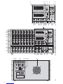 3
3
-
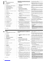 4
4
-
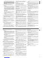 5
5
-
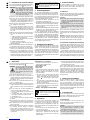 6
6
-
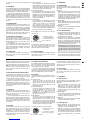 7
7
-
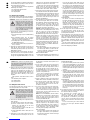 8
8
-
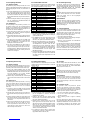 9
9
-
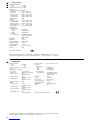 10
10
-
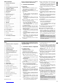 11
11
-
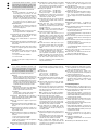 12
12
-
 13
13
-
 14
14
-
 15
15
-
 16
16
-
 17
17
-
 18
18
-
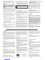 19
19
-
 20
20
-
 21
21
-
 22
22
-
 23
23
-
 24
24
-
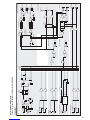 25
25
-
 26
26


IMG Stage Line PMX-800DSP Instrukcja obsługi
- Kategoria
- Miksery audio
- Typ
- Instrukcja obsługi
w innych językach
- italiano: IMG Stage Line PMX-800DSP Manuale utente
- français: IMG Stage Line PMX-800DSP Manuel utilisateur
- English: IMG Stage Line PMX-800DSP User manual