
8
HOUSE & GARDEN WATER PUMP PHGA 1300 A1
HAUS- UND GARTENAUTOMAT PHGA 1300 A1
POMPE POUR JARDIN ET MAISON PHGA 1300 A1
IAN 393888_2107
CHAT
HAUS- UND GARTENAUTOMAT
Bedienungs- und Sicherheitshinweise
Originalbetriebsanleitung
DE
BE
HUIS- EN TUINAUTOMAAT
Bedienings- en veiligheidsinstructies
Vertaling van de originele handleiding
NL
HOUSE & GARDEN WATER PUMP
Operating and Safety Instructions
Translation of Original Operating Manual
GB IE
BE
POMPE POUR JARDIN ET MAISON
Consignes d‘utilisation et de sécurité
Traduction des instructions d’origine
FR
HYDROFOR DOMOWY I OGRODOWY
Wskazówki dotyczące obsługi i bezpieczeństwa
Tłumaczenie oryginalnej instrukcji obsługi
PL
DOMÁCI A ZÁHRADNÝ VODNÝ AUTOMAT
Pokyny pre obsluhu a bezpečnostné pokyny
Preklad originálneho návodu na obsluhu
SK
DOMÁCÍ A ZAHRADNÍ VODNÍ AUTOMAT
Pokyny pro obsluhu a bezpečnostní pokyny
Překlad originálního provozního návodu
CZ
BOMBA DE SUPERFICIE PARA CASA Y JARDÍN
Instrucciones de utilización y de seguridad
Traducción del manual de instrucciones original
ES
HUS- OG HAVEAUTOMAT
Drifts- og sikkerhedsinstruktioner
Oversættelse af den originale driftsvejledning
DK
HÁZI ÉS KERTI AUTOMATA
Kezelési és biztonsági útmutató
Az eredeti használati útmutató fordítása
HU
HIŠNI IN VRTNI AVTOMAT
Navodila za upravljanje in varnostna opozorila
Prevod originalnega navodila za uporabo
SI
POMPA AUTOMATICA PER CASA E GIARDINO
Indicazioni per l’uso e per la sicurezza
Traduzione delle istruzioni d’uso originali
IT MT

GB / IE Operating and Safety Instructions Page 01
DE / AT / CH Bedienungs- und Sicherheitshinweise Seite 12
FR / BE Consignes d‘utilisation et de sécurité Page 23
NL / BE Bedienings- en veiligheidsinstructies Pagina 35
CZ Pokyny pro obsluhu a bezpečnostní pokyny Strana 46
PL Wskazówki dotyczące obsługi i bezpieczeństwa Strona 57
SK Pokyny pre obsluhu a bezpečnostné pokyny Strana 68
ES Instrucciones de utilización y de seguridad Página 78
DK Drifts- og sikkerhedsinstruktioner Side 89
IT / MT Indicazioni per l’uso e per la sicurezza Pagina 99
HU Kezelési és biztonsági útmutató Oldal 110
SI Navodila za upravljanje in varnostna opozorila Stran 122
Klappen Sie vor dem Lesen die Seite mit den Abbildungen aus und machen Sie sich anschließend mit allen Funktionen des Gerätes vertraut.
DE AT CH
Avant de lire le mode d‘emploi, ouvrez la page contenant les illustrations et familiarisez-vous ensuite avec toutes les fonctions de l‘appareil.
FR BE
Vouw vóór het lezen de pagina met de afbeeldingen open en maak u vertrouwd met alle functies van het apparaat.
NL BE
Před čtením si otevřete stranu s obrázky a potom se seznamte se všemi funkcemi přístroje.
CZ
Before reading, unfold the page containing the illustrations and familiarise yourself with all functions of the device.
GB IE
Antes de empezar a leer abra la página que contiene las imágenes y, en seguida, familiarícese con todas las funciones del dispositivo.
ES
Przed przeczytaniem proszę rozłożyć stronę z ilustracjami, a następnie proszę zapoznać się z wszystkimi funkcjami urządzenia.
PL
Pred čítaním si odklopte stranu s obrázkami a potom sa oboznámte so všetkými funkciami prístroja.
SK
Før du læser, vend siden med billeder frem og bliv bekendt med alle apparatets funktioner.
DK
Prima di leggere aprire la pagina con le immagini e prendere confidenza con le diverse funzioni dell’apparecchio.
IT MT
Olvasás előtt kattintson az ábrát tartalmazó oldalra és végezetül ismerje meg a készülék mindegyik funkcióját.
HU
Pred branjem odprite stran s slikami in se nato seznanite z vsemi funkcijami naprave.
SI

1
1
•
/ f
#�,
4�
-0
)
\
�m
m
m
.
\
D
1
d
(
-= r
,
¾
-
'
IM
'
Ir
�=
-1
1
11
10a
1a
7
2
3
4
5
6
213
12
11
9
8
9
1
13b
13a
14
10

Power On
3
Automatic Mode
4
Automatic Mode
L
4.1
Automatic Mode
P L
4.2
Automatic Mode
P
4.3
Automatic Mode
P
VALVE CLOSED
4.4
Automatic Mode
Check Water
4.5
Time Mode
5

Time On 00:00
Save Set Exit
Time Off 00:00
Save Set Exit
Time On 13:00
Time Off 13:15
Time Mode
NOT SET
Time Now 00:00
Save Set Exit
Time Now 00:00
Next + -
Time Now 00:00
Save Set Exit
Time Mode
12 : 30 : 36
6 7
8 9
10 11
12 13

Always - On Mode
Not Recommended
14 15
16 1
10
17
15a
a
c
b
7
13
13

1GB/IE
Table of contents: Page:
1. Explanation of the symbols on the device ......................................................................................................................................................... 2
2. Introduction ..........................................................................................................................................................................................................3
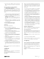
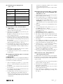
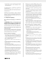
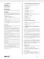
3. Device description (fig. 1-2) ...............................................................................................................................................................................3
4. Scope of delivery ................................................................................................................................................................................................ 3
5. Proper use ............................................................................................................................................................................................................3
6. Safety instructions ...............................................................................................................................................................................................4
7. Technical data .....................................................................................................................................................................................................5
8. Before commissioning .........................................................................................................................................................................................5
9. Installation............................................................................................................................................................................................................5
10. Operation ............................................................................................................................................................................................................6
11. Uninstallation/Transport .....................................................................................................................................................................................7
12. Maintenance .......................................................................................................................................................................................................7
13. Storage ................................................................................................................................................................................................................8
14. Electrical connection ...........................................................................................................................................................................................8
15. Disposal and recycling .......................................................................................................................................................................................8
16. Troubleshooting .................................................................................................................................................................................................10
17. Warranty certificate ..........................................................................................................................................................................................11
18. Exploded view ................................................................................................................................................................................................133
19. Declaration of conformity .............................................................................................................................................................................. 135

2GB/IE
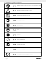
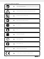
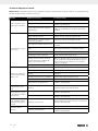
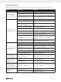
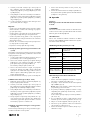
1. Explanation of the symbols on the device
GB IE Before commissioning, read and observe the operating manual and safety instructions!
GB IE Observe warning and safety instructions!
GB IE Specification of the sound power level in dB
GB IE Input voltage / frequency
GB IE Nominal power
GB IE Weight
l/h
GB IE Flow rate per hour
GB IE Max. pressure delivered
GB IE Max. fluid temperature
IP X4 GB IE Protected from water splashes
GB IE The product complies with the applicable European directives.

3GB/IE
2. Introduction
MANUFACTURER:
Scheppach GmbH
Günzburger Straße 69
D-89335 Ichenhausen
DEAR CUSTOMER,
We hope your new tool brings you much enjoyment and suc-
cess.
NOTE:
In accordance with the applicable product liability laws, the
manufacturer of this device assumes no liability for damage to
the device or caused by the device arising from:
• Improper handling
• Failure to comply with the operating instructions.
• Repairs carried out by third parties, unauthorised specialists.
• Installing and replacing non-original spare parts,
• Improper use
• Failures of the electrical system in the event of the electri-
cal regulations and VDE provisions 0100, DIN 57113 /
VDE0113 not being observed.
Note:
Read the whole text of the operating manual before assembly
and commissioning.
This operating manual should help you to familiarise yourself
with your product and to use it for its intended purpose.
The operating manual includes important instructions for the
safe, proper and economic operation of the product, for avoid-
ing danger, for minimising repair costs and downtimes and for
increasing the reliability and extending the service life of the
product.
In addition to the safety instructions in this operating manual,
you must also observe the regulations applicable to the opera-
tion of the product in your country.
Keep the operating manual package with the power tool at
all times and store it in a plastic cover to protect it from dirt
and moisture. They must be read and carefully observed by all
operating personnel before starting the work.
The product may only be used by personnel who have been
trained to use it and who have been instructed with respect to
the associated hazards.
The required minimum age must be observed.
In addition to the safety instructions in this operating manual
and the separate regulations of your country, the generally
recognised technical rules relating to the operation of such ma-
chines must also be observed.
We accept no liability for accidents or damage that occur due
to a failure to observe this manual and the safety instructions.
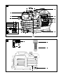
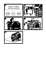
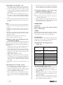
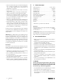
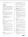
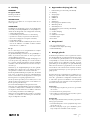
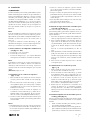
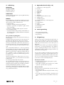
3. Device description (fig. 1-2)
1. Pressure connection (1 inch internal thread)
1a Locking screw
2. Transport handle
3. LCD display
4. MODE button
5. SET button
6. CHECK button
7. Fastening points (diameter of 6 mm)
8. Ventilation screw
9. Water drain plug
10. Suction connection (1 inch internal thread)
10a Locking screw
11. Pre-filter locking screw
12. Pre-filter
13. Multifunction adapter
13a Double nipple
13b Angle piece
4. Scope of delivery
• Garden pump and domestic waterworks
• 2x multifunction adapters (two pieces)
• Operating manual
5. Proper use
The machine may only be used in the intended manner. Any
use beyond this is improper. The user/operator, not the manu-
facturer, is responsible for damages or injuries of any type re-
sulting from this.
An element of the intended use is also the observance of the
safety instructions, as well as the assembly instructions and op-
erating information in the operating manual. Persons who oper-
ate and maintain the machine must be familiar with it and must
be informed about potential dangers.
In addition, the applicable accident prevention regulations
must be strictly observed. Other general occupational health
and safety-related rules and regulations must be observed. The
liability of the manufacturer and resulting damages are exclud-
ed in the event of modifications of the machine.
Area of application
• For watering and irrigation of green areas, vegetable beds
and gardens.
• For operating lawn sprinklers.
• With pre-filter for drawing water from ponds, streams, rain-
water barrels, rainwater cisterns and wells.
Pumped media
For pumping clear water (fresh water), rainwater or light deter-
gent solutions / domestic water.
• The maximum temperature of the pumped liquid must not
exceed +35°C.
• This garden pump and domestic waterworks must not be
used to pump flammable, gaseous or explosive liquids.
• The pumping of aggressive liquids (acids, lyes, silo seepage
juice etc.), as well as liquids with abrasive (sanding) materi-
als (sand) must also be avoided.

4GB/IE
The machine may only be operated with original parts and
original accessories from the manufacturer.
The safety, operating and maintenance specifications of the
manufacturer, as well as the dimensions specified in the techni-
cal data, must be observed
Please note that our equipment was not designed with the inten-
tion of use for commercial or industrial purposes. We assume
no guarantee if the device is used in commercial or industrial
applications, or for equivalent work.
6. Safety instructions
General power tool safety warnings
m WARNING! Read all safety warnings, instruc-
tions, illustrations and specifications provided with
this electric tool. Failure to follow all instructions listed be-
low may result in electric shock, fire and/or serious injury.
Save all warnings and instructions for future refer-
ence.
The term “power tool” in the warnings refers to your mains-
operated (corded) power tool or battery-operated (cordless)
power tool.
General safety instructions
• This product can be used by children from 8 years of age as
well as by persons with reduced physical, sensory or mental
capabilities or with a lack of experience or knowledge, if
they are supervised or if they have been trained in the safe
use of the device and understand the resultant hazards.
• Children may not play with the product.
• Cleaning and user maintenance must not be carried out by
children unsupervised.
• Persons who are unfamiliar with the operating manual may
not use the product. The product is not to be used by persons
under the age of 16.
• The product must not be operated if there are people in the
water.
• Keep children away from the running engine.
• Dispose of the packaging material properly.
• Do not use the product in the vicinity of combustible fluids
or gases. There is a risk of fire or explosion if disregarded.
• The pumping of aggressive, abrasive (scouring), corrosive,
flammable (e.g. motor fuels) or explosive liquids, salt water,
cleaning agents and foodstuffs is not permitted.
• Store the product in a dry place and out of reach of children.
• The temperature of the pumped liquid shall not exceed
35°C.
• Do not work with a damaged, incomplete or modified prod-
uct without the consent of the manufacturer. Before commis-
sioning, have a specialist check that the required electrical
protective measures are in place.
• Supervise the product during operation in order to protect
the garden pump and domestic waterworks for automatic
shut-down and against running dry. Check the function of the
float switch regularly (see chapter “Commissioning”).
Failure to do so will invalidate warranty and liability claims.
• Please note that the garden pump and domestic waterworks
is not suitable for continuous operation (e.g. for watercours-
es in garden ponds). Regularly check the product for proper
function.
• Please note that lubricants are used in the product, which
may cause damage or contamination due to leakage. Do
not use the garden pump and domestic waterworks in gar-
den ponds with fish or valuable plants. If lubricants leak out,
they may contaminate the liquid.
• Do not carry or attach the product by the cable or hose.
• Protect the product against frost and running dry.
• Only use original spare parts and accessories and do not
modify the product.
• Please read the information on “Cleaning, maintenance,
storage” in the operating manual. All additional measures,
in particular opening the product, must be carried out by a
qualified electrician. In the event of repair, always contact
our service centre.
Electrical safety instructions
• When operating the product, the power plug must be freely
accessible after installation.
• Before you put your new the garden pump and domes-
tic waterworks and into operation, have it professionally
checked:
-Earthing, connection of the neutral line and residual cur-
rent circuit breaker must comply with the safety regulations
of the power supply companies and function properly,
-Protect the electrical plug connections from moisture.
-If there is a risk of flooding, fit the plug connections in the
flood-proof area.
• Ensure that the mains voltage corresponds to the specifica-
tions on the type plate.
• Carry out the electrical installation in accordance with the
national regulations.
• Only connect the product to a socket with a residual cur-
rent circuit breaker (FI switch) with a rated residual trigger-
ing current of up to 30 mA; Fuse at least 6 amps.
• Before each use, always check the product, cable and plug
for damages. Defective cables must not be repaired but re-
placed with a new ones.
Have product damages repaired by a specialist.
• If the connection cable of this product is damaged it must be
replaced by the manufacturer or their customer services per-
sonnel or by a similarly qualified person, in order to avoid
hazards.
• Do not use the cable to pull the plug out of the outlet.
• Protect the cable from heat, oil and sharp edges.
• Do not carry or attach the product by the cable.
• Use only extension cables that are splash-proof and intend-
ed for outdoor use. Always unroll a cable drum completely
before use. Check the cable for damage.
• Pull out the mains plug before all work on the product, in
work breaks and when not in use.
• Mains connection cables shall not have a smaller cross-sec-
tion than rubber hose lines with the designation H05RN-F
3*0.75 mm². The cable length must be 10 m. The conduc-
tor core cross-section of the extension cable must be at least
1.5 mm2.

5GB/IE
Lubricants are used inside the garden pump and domestic wa-
terworks and can contaminate the drained fluids, if the product
is improperly operated or damaged.
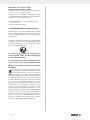
Warning! This electric tool generates an electromagnetic
field during operation. This field can impair active or passive
medical implants under certain conditions. In order to prevent
the risk of serious or deadly injuries, we recommend that per-
sons with medical implants consult with their physician and
the manufacturer of the medical implant prior to operating the
power tool.
Residual risks
The machine has been built according to the state-of-the-art
and the recognised technical safety requirements. However,
individual residual risks can arise during operation.
• Health hazard due to electrical power, with the use of im-
proper electrical connection cables.
• Before performing setting or maintenance work, unplug the
mains plug.
• Furthermore, despite all precautions having been met, some
non-obvious residual risks may still remain.
• Residual risks can be minimised if the “Safety Instructions”
and the “Intended Use” together with the operating manual
as a whole are observed.
7. Technical data
AC motor.............................................................. 230 V∼ 50 Hz
Nominal power S3* ................................................. 1300 watts
Max. delivery flow ........................................................5000 l/h
Max. delivery height ............................................................50 m
Max. delivery pressure ....................................................... 5 bar
Max. suction height ................................................................8 m
Pressure and suction connection .........................................G 1”
Max. dirt particle size ..................................................... 0.5 mm
Max. water temperature .................................................. 35° C
Protection class ............................................................................I
Protection category ............................................................... IPX4
Operating mode* ....................................................................S3
Weight .................................................................................12 kg
* Operating mode S3, periodic intermediate duty.
Noise
The noise values have been determined in accordance with
EN 3744.
Sound power level LwA...................................................76 dB(A)
Uncertainty KpA/wA .................................................................1 dB
m Warning: Noise can have serious effects on your
health. If the machine noise exceeds 85 dB (A), please wear
suitable hearing protection.
8. Before commissioning
• Open the packaging and carefully remove the product.
• Remove the packaging material, as well as the packaging
and transport safety devices (if present).
• Check whether the scope of delivery is complete.
• Check the product and accessory parts for transport dam-
age. In the event of complaints the carrier must be informed
immediately. Later claims will not be recognised.
• If possible, keep the packaging until the expiry of the war-
ranty period.
• Familiarise yourself with the product by means of the operat-
ing manual before using for the first time.
• With accessories as well as wearing parts and replacement
parts use only original parts. Replacement parts can be ob-
tained from your dealer.
• When ordering please provide our article number as well as
type and year of manufacture for the product.
m DANGER!
The device and the packaging are not children‘s
toys! Do not let children play with plastic bags,
films or small parts! There is a danger of choking
or suffocating!
• Prior to commissioning, all covers and safety devices must be
mounted correctly.
• Before connecting the machine, make certain that the data
on the type plate matches with the mains power data.
9. Installation
m NOTE!
The garden pump and domestic waterworks can also be in-
stalled for domestic water supply indoors. To minimise vibra-
tions and noises, the garden pump and domestic waterworks
should be connected to the pipe network with flexible hoses. It
is also recommended to use anti-vibration material, e.g. to put
a rubber layer between the garden pump and domestic water-
works and the machine base. Ensure that the pump is securely
fastened using screws which fit through the screw brackets (7).
Note:
The connections for the suction and pressure connection have
been set with 1 inch at the factory. Optionally, you can use the
multifunctional adapter supplied, which offers further connec-
tion options (see point 9.1).
An additional connection system (such as a tap, hose clamp,
bayonet fitting) is required for installation and is not included in
the scope of delivery.
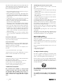
9.1 Function of the multifunction adapter (13)
(fig. 15 + 15a)
a. Connection (a) 1 1/4” male thread
b. Connection (b) 1” male thread
c. Hose connection (c) 1” (hose clamp is required! Not in-
cluded in the scope of delivery!)
Note:
To use connection (b), hose connection (c) must be cut off with
a knife (not included in the scope of delivery) (see cutting mark
in fig. 15)! After you have cut off the hose connection, it can
no longer be used.
Attention! Risk of cuts!

6GB/IE
9.2 Installing a suction line (fig. 1 + 15)
1. Remove the locking screw (10a) on the suction connection
(10). Keep the locking screw (10a) in a safe place (fig. 1)!
2. Connect the appropriate connection system (e.g. quick
coupling system, bayonet fitting) or the multifunction adapt-
er (13) with the help of connection (a) to the suction con-
nection (10).
3. Then connect the suction line with the appropriate connec-
tion system (e.g. quick coupling system, bayonet fitting). If
necessary, use connection (c) of the multifunction adapter
(13).
4. Lay the suction line from the water pick-up point to the gar-
den pump and domestic waterworks in a continuously ris-
ing slope.
Notes:
• Please do not lay the suction line above the pump height. Air
bubbles in the suction line will delay and prevent the suction
process.
• Install the suction and pressure lines in order to avoid a me-
chanical pressure on the garden pump and domestic wa-
terworks.
• Place the suction line deep enough in the water to prevent
the garden pump and domestic waterworks from running dry
if the water level drops.
• Check the suction hose for leaks, to avoid sucking air.
• Avoid sucking in foreign bodies (sand etc.).
9.3 Filling the garden pump and domestic water-
works with water (fig. 16)
In order to reduce the start-up time of the garden pump and
domestic waterworks and to prevent air being sucked in, the
garden pump and domestic waterworks must be filled with wa-
ter beforehand!
1. Therefore, the suction hose should be installed to prevent
water from flowing out of the suction connection (10).
2. Use the opening of the pressure connection (1) to fill the
garden pump and domestic waterworks with water. Alter-
natively, you can fill in water through the opening of the
pre-filter locking screw (11).
Approx. 2.5 litres of water are required.
3. Slightly tilt the garden pump and domestic waterworks
now and then, to avoid air being trapped. Alternatively,
open the ventilation screw (8) and fill up with water until
water comes out of it. Afterwards, attach the ventilation
screw again.
4. Now, attach the pressure line as described in the next
point.
9.4 Installing a pressure line (fig. 1 and 2)
1. Remove the locking screw (1a) from the pressure connec-
tion (1). Keep the locking screw (1a) in a safe place!
2. Connect the appropriate connection system (e.g. quick
coupling system, bayonet fitting) to the pressure connec-
tion (1) or the multifunction adapter (a or b).
3. Then connect the pressure hose with the appropriate con-
nection system (e.g. quick coupling system, bayonet fitting).
If necessary, use connection c of the multifunction adapter
(13).
4. During the suction process, the consumers in the pressure
line (e.g. nozzles, showers, toilet flush, etc.) must be fully
opened so that the air in the suction line can escape freely.
9.5 Permanent installation of the garden pump
and domestic waterworks (fig. 17)
For stationary use of the garden pump and domestic water-
works, we recommend a permanent installation on a level sur-
face.
1. Only set up the garden pump and domestic waterworks on
a screwable and flat surface.
2. Install the garden pump and domestic waterworks on the
fastening points (7). Use adequate assembly material for
this (not included in the scope of delivery!).
10. Operation
m Attention!
Always make sure the product is fully assembled
before commissioning!
m NOTE!
The garden pump and domestic waterworks must be absolutely
tight at the inlet and outlet. Therefore, regardless of your cho-
sen connection, use a Teflon or any other sealing tape.
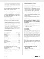
10.1 LCD display
The garden pump and domestic waterworks offers a range of
setting options. You can select one of the operating modes on
the LCD display (3) with the “MODE” button (4).
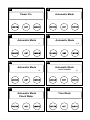
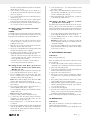
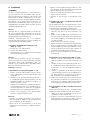
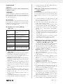
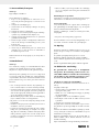
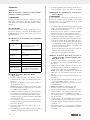
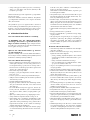
10.2 Explanation of the display functions
(fig. 3 - 14)
Power On
Garden pump and domestic water-
works is connected to an electrical
power source
Automatic Mode Garden pump and domestic water-
works is running automatically
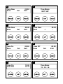
Time Mode Setting the time and operating time
Time Now Setting the current time
Time On Setting the power-on time
Time Off Setting the power-off time
Time Mode NOT SET Current time has not been set
Always On Mode
(Not Recommended)
Garden pump and domestic water-
works runs continuously, not recom-
mended
10.3 “Automatic Mode” (fig. 3 - 4.4)
1. Connect the garden pump and domestic waterworks to the
power supply The display shows “Power on” (fig. 3).
2. Press the “MODE” button (4) one time to reach the “Auto-
matic Mode” (fig. 4).
Attention: Garden pump and domestic waterworks
doesn’t immediately start Please ensure that the product is
completely assembled.
3. When you operate your consumer attached to the pres-
sure line (e.g. nozzle, shower, toilet flush, etc.), the garden
pump and domestic waterworks switches on.

7GB/IE
The water is pumped and the flow is marked on the display
with the letter “L” (fig. 4.1).
4. If the consumer is closed again, pressure builds up in
the garden pump and domestic waterworks. The display
shows “P L” (fig. 4.2).
5. As soon as the maximum pressure is reached, the letter “L”
disappears (fig. 4.3).
6. The display then shows “Valve closed P” and the garden
pump and domestic waterworks switches off (fig. 4.4).
7. The garden pump and domestic waterworks starts again
as soon as the consumer is opened again.
10.4 Safety switch (only available in automatic
mode) (fig. 4.5)
m NOTE!
In automatic mode, the garden pump and domestic waterworks
has a safety switch to prevent it from running dry and causing
the garden pump and domestic waterworks to malfunction.
1. If the garden pump and domestic waterworks doesn’t
recognise any flow “L” and any pressure “P”, it continues
pumping for 60 seconds.
2. After these 60 seconds, the garden pump and domestic
waterworks switches off for 20 seconds.
3. This process is repeated three times until the garden pump
and domestic waterworks stops completely.
4. The display now indicates that you need to check the water
supply:”Automatic Mode - Check Water” (fig. 4.5).
-Place the suction line deep enough in the water to pre-
vent the garden pump and domestic waterworks from
running dry if the water level drops.
-Check the suction hose for leaks, to avoid sucking air.
-Avoid sucking in foreign bodies (sand etc.).
10.5 Setting the time “Time Now”, the power-on
time “Time On” and the power-off time “Time
Off” (fig. 3, 5 - 13)
1. Connect the garden pump and domestic waterworks to the
power supply The display shows “Power on” (fig. 3).
2. Press the “MODE” button (4) several times until “Time
Mode” is displayed (fig. 5). After a brief waiting time,
“Time Now” appears in the display (fig. 9).
Note: After a while, the display shows “Time Mode NOT
SET” if no time setting has been made (fig. 7).
3. Now press the “SET” button (5) to activate the time setting
function (fig. 8).
4. Then, set the current time using the “SET” button (5) for “+”
and the “MODE” button (4) for “-” (fig. 9).
You can change the settings for hours and minutes with the
“CHECK” button (6).
Note:00:00 (hh/mm)– 24h time mode.
5. Confirm your settings with the “CHECK” button (6).
6. To set the time when the garden pump and domestic
waterworks is to switch on (“Time On” mode), press the
“CHECK” button (6) again. (fig. 10)
7. Now, repeat the steps 3 – 5, to set the power-on time and
to confirm it.
8. By pressing the “CHECK” button (6) again, the display will
show the “Time Off” mode. In this mode you determine the
time at which the garden pump and domestic waterworks
should switch off (fig. 11).
9. Now, repeat the steps 3 – 5, to set the automatic power-off
time and to confirm it.
10. The switch-on and switch-off times then appear in the dis-
play “Time On / Time Off” (Fig. 12). It is not necessary to
press the “CHECK” button (6) again.
11. After a brief waiting time, “Time Mode” (fig. 13) appears
on the display showing the time set.
10.6 “Always On Mode” continuous operation
(fig. 14) (not recommended)
The garden pump and domestic waterworks can also be oper-
ated in continuous mode. In this mode there is no automatic
safety switch and therefore the garden pump and domestic wa-
terworks may only be operated under continuous observation!
1. Connect the garden pump and domestic waterworks to the
power supply The display shows “Power on” (fig. 3).
2. Press the “MODE” button (4) one time to reach the “Al-
ways On Mode” (fig. 14).
Attention: Garden pump and domestic waterworks
doesn’t immediately start Please ensure that the product is
completely assembled.
3. By pressing the “MODE” button (4) again, the garden
pump and domestic waterworks switches off. The display
shows “Power on” (fig. 3).
11. Uninstallation/Transport
m Attention!
Always unplug the mains plug.
Empty the garden pump and domestic waterworks housing
prior to transport.
1. Provide a drip tray with a volume of approx. 5 liters (not in-
cluded in the scope of delivery) for the water to be drained.
2. Remove the water drain plug (9).
3. Let the water completely flow out of the garden pump and
domestic waterworks into the drip tray.
4. Remove the suction and pressure hose.
5. Remove the connection systems or multifunction adapters
(13) attached to your garden pump and domestic water-
works.
6. If the garden pump and domestic waterworks is perma-
nently installed, remove the assembly material.
7. Afterwards tilt the garden pump and domestic waterworks
until the residual water flows through the suction and pres-
sure connection (10 and 1).
8. Screw the water drain plug (9).
9. Close the suction and pressure hoses (10 and 1) using the
locking screws (1a and 10a) to protect the garden pump
and domestic waterworks from dust and dirt.
Always use the transport handle (2) for transporting the product.
12. Maintenance
m Attention!
Only carry out maintenance, cleaning and adjustment work
when the mains plug is pulled out.
We recommend that you clean the product directly after every
use.

8GB/IE
Clean the product at regular intervals using a damp cloth and
a little soft soap. Do not use any cleaning products or solvents;
they could attack the plastic parts of the product. Make sure
that no water can penetrate the motor.
• We recommend regular inspections and care for a long ser-
vice life (i. e. at least once a month).
• Before extended periods of inactivity or through the winter,
the garden pump and domestic waterworks should be thor-
oughly flushed through with water, emptied completely and
then stored dry.
• To empty the housing, loosen the water drain screw (9) and
tilt the garden pump and domestic waterworks slightly.
• If there is a risk of frost the garden pump and domestic wa-
terworks must be completely emptied.
• After longer periods of storage check the pump by switching
on/off briefly in order to check that the rotor turns normally.
• In the event of the garden pump and domestic waterworks
being jammed connect the pressure line to the water supply
line and remove suction hose. Open the water supply line.
Switch the garden pump and domestic waterworks on for
ca. two seconds several times. This method rectifies block-
ages in most cases.
• To clean the pre-filter (12) unscrew the pre-filter locking
screw (11) and remove it. Afterwards, clean it with clear
water.
Connections and repairs
Connections and repair work on the electrical equipment may
only be carried out by electricians.
Service information
With this product, it is necessary to note that the following parts
are subject to natural or usage-related wear, or that the follow-
ing parts are required as consumables.
Wearing parts*:Seals, pre-filter, flow sensor impeller, non-re-
turn valve
* may not be included in the scope of supply!
Spare parts and accessories can be obtained from our Service
Centre. To do this, scan the QR code on the front page.
13. Storage
Store the device and its accessories in a dark, dry and frost-free
place that is inaccessible to children.
The optimum storage temperature is between 5 and 30˚C.
Store the electric tool in its original packaging.
Cover the electric tool to protect it from dust or moisture.
Store the operating manual with the electric tool.
14. Electrical connection
The electrical motor installed is connected and
ready for operation. The connection complies with
the applicable VDE and DIN provisions. The cus-
tomer‘s mains connection as well as the extension
cable used must also comply with these regula-
tions.
14.1 Damaged electrical connection cable
The insulation on electrical connection cables is often dam-
aged.
This may have the following causes:
• Pressure points, where connection cables are passed through
windows or doors.
• Kinks where the connection cable has been improperly fas-
tened or routed.
• Places where the connection cables have been cut due to
being driven over.
• Insulation damage due to being ripped out of the wall outlet.
• Cracks due to the insulation ageing.
Such damaged electrical connection cables must not be used
and are life-threatening due to the insulation damage.
Check the electrical connection cables for damage regularly.
Ensure that the connection cables are disconnected from elec-
trical power when checking for damage.
Electrical connection cables must comply with the applicable
VDE and DIN provisions. Only use connection cables of the
same designation.
The printing of the type designation on the connection cable
is mandatory.
If the mains connection cable of this device is damaged, it must
be replaced by a special connection cable which can be ob-
tained from the manufacturer or its service department.
AC motor 230 V∼ / 50 Hz
Mains voltage 230 V∼ / 50 Hz.
Mains power connection and extension leads must be 3-core =
P + N + SL. - (1/N/PE).
Extension cables up to 25 m long must have a cross-section of
1.5 mm². The mains power connection must be protected with
a max. 16A fuse.
Please provide the following information in the event of any
enquiries:
• Type of current for the motor
• Engine data - type plate
15. Disposal and recycling
The device is supplied in packaging to avoid transport dam-
ages. This packaging is raw material and can thus be used
again or can be reintegrated into the raw material cycle.
The device and its accessories are made of different materials,
such as metal and plastic. Take defective components to spe-
cial waste disposal sites. Check with your specialist dealer or
municipal administration!
The packaging is made of environmentally friend-
ly materials that can be disposed of at your local
recycling centre.
You can find out how to dispose of the disused de-
vice from your local authority or city administra-
tion.

9GB/IE
Do not throw old equipment away with household
waste!
This symbol indicates that this product must not be dis-
posed of in household waste as per Waste Electrical
and Electronic Equipment directive (2012/19/EU) and
national laws. This product must be handed over at the
intended collection point. This can be done, for example, by
returning it when purchasing a similar product or delivering it to
an authorised collection point for the recycling of old electrical
and electronic devices. Improper handling of old devices can
have negative effects on the environment and on human health
due to potential hazardous materials which are often con-
tained in old electrical and electronic devices. By disposing of
this product properly, you are also contributing to the effective
use of natural resources. Information about collection points for
old devices can be found at your municipal authority, the local
disposal provider, an authorised location for the disposal of old
electrical and electronic devices or your waste collection ser-
vice.

10 GB/IE
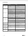
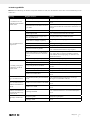
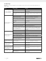
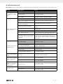
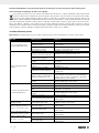
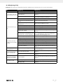
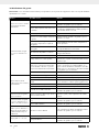
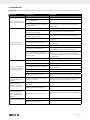
16. Troubleshooting
Note: When returning the device for repair, please ensure for safety reasons that it is empty and dry when it is sent to the service centre.
Fault Possible cause Remedy
Motor does not start or
suddenly stops during
operation
No mains voltage Check mains voltage
Electrical interruption Have the garden pump and domestic waterworks checked
in a specialist workshop.
Pump impeller jammed and thermal sensor
has tripped
Disconnect the garden pump and domestic waterworks
from the power supply, dismantle and clean the hoses and
connections
Garden pump and domestic
waterworks does not suck
Suction valve not in the water Put the suction valve in the water
Garden pump and domestic waterworks not
filled with pumped liquid Fill garden pump and domestic waterworks with water
Garden pump and domestic waterworks
sucks in air at a connection point Seal the suction-side connections airtight
Leaky or damaged suction hose Check suction hose for damages and seal airtight
Pre-filter locking screw leaks Check seal and replace it if necessary - tighten hand-tight
Max. suction height exceeded Check suction height
Waiting time was not maintained Turn on the garden pump and domestic waterworks and
wait until it pumps water
Air cannot escape because the pressure
hose is closed or there is residual water in
the pressure hose
Open the consumer which is connected to the pressure line
(z. B. nozzles, showers, etc.), or empty the pressure line or
remove is from the garden pump and domestic waterworks
when pumping.
Pre-filter or suction line clogged Clean pre-filter or suction line
Motor runs, but the flow
rate or pressure suddenly
drops
Suction height too high Check suction height
Water level dropping rapidly Position suction valve lower
Garden pump and domestic waterworks
performance reduces due to hazardous
substances
Clean garden pump and domestic waterworks and
replace worn parts
Pre-filter or suction line clogged Clean pre-filter or suction line
Suction-side leaks Seal suction-side
Flow sensor impeller blocks Have the garden pump and domestic waterworks checked
in a specialist workshop.
Thermal sensor shuts off the
garden pump and domestic
waterworks
Motor overloaded, friction too high due to
foreign bodies
Dismantle garden pump and domestic waterworks and
clean, avoid suctioning foreign bodies
Garden pump and domestic
waterworks does not switch
off in automatic mode
Flow sensor impeller worn or defective Have the garden pump and domestic waterworks checked
in a specialist workshop.
Flow sensor defective Have the garden pump and domestic waterworks checked
in a specialist workshop.
In automatic mode, the
garden pump and domestic
waterworks unintentionally
switches on again after it
has been switched off
Non-return valve defective Have the garden pump and domestic waterworks checked
in a specialist workshop.
LCD display doesn’t switch
on
No mains voltage Check mains voltage
LCD display defective Have the garden pump and domestic waterworks checked
in a specialist workshop.

11GB/IE
17. Warranty certificate
Dear Customer,
All of our products undergo strict quality checks to ensure that they reach you in perfect condition. In the unlikely event that your device devel-
ops a fault, please contact our service department at the address shown on this guarantee card. Of course, if you would prefer to call us then
we are also happy to offer our assistance under the service number printed below. Please note the following terms under which guarantee
claims can be made:
• These guarantee terms cover additional guarantee rights and do not affect your statutory warranty rights. We do not charge you for this
guarantee.
• Our guarantee only covers problems caused by material or manufacturing defects, and it is restricted to the rectification of these defects
or replacement of the device. Please note that our devices have not been designed for use in commercial, trade or industrial applications.
Consequently, the guarantee is invalidated if the equipment is used in commercial, trade or industrial applications or for other equivalent
activities. The following are also excluded from our guarantee: compensation for transport damage, damage caused by failure to comply
with the installation/assembly instructions or damage caused by unprofessional installation, failure to comply with the operating instruc-
tions (e.g. connection to the wrong mains voltage or current type), misuse or inappropriate use (such as overloading of the device or use
of non-approved tools or accessories), failure to comply with the maintenance and safety regulations, ingress of foreign bodies into the
device (e.g. sand, stones or dust), effects of force or external influences (e.g. damage caused by the device being dropped) and normal
wear resulting from proper operation of the device.
The guarantee is rendered null and void if any attempt is made to tamper with the device.
• The guarantee is valid for a period of 3 years starting from the purchase date of the device. Guarantee claims should be submitted be-
fore the end of the guarantee period within two weeks of the defect being noticed. No guarantee claims will be accepted after the end
of the guarantee period. The original guarantee period remains applicable to the device even if repairs are carried out or parts are re-
placed. In such cases, the work performed or parts fitted will not result in an extension of the guarantee period, and no new guarantee
will become active for the work performed or parts fitted. This also applies when an on-site service is used.
• In order to assert your guarantee claim, please contact the service partner shown below. If the complaint is within the guarantee period,
we will provide you with a return slip, with which you can return your defective device free of charge to us. It would help us if you could
describe the nature of the problem in as much detail as possible. If the defect is covered by our guarantee then your device will either
be repaired immediately and returned to you, or we will send you a new device.
Of course, we are also happy offer a chargeable repair service for any defects which are not covered by the scope of this guarantee or for
units which are no longer covered. To take advantage of this service, please send the device to our service address.
Service-Hotline (GB): Service-Hotline (IE):
00800 4003 4003 00800 4003 4003
(0,00 EUR/Min.) (0,00 EUR/Min.)
Service-Email (GB): Service-Email (IE):
Service Address (GB): Service Address (IE):
Forest Park & Garden LetMeRepair
Coed Court, Taffsmead Road 1 Langlands Court / Kelvin South Business Park
Treforest, Ind. Estate, Pontypridd CF375SW East Kilbride G75 0YB
At www.lidl-service.com you can download this and many more manuals, product videos plus installation soft-
ware.
The QR code takes you directly to the Lidl service page (www.lidl-service.com) and you can open your operat-
ing manual by entering the article number (IAN) 393888_2107.

12 DE/AT/CH
Inhalt: Seite:
1. Erklärung der Symbole auf dem Gerät............................................................................................................................................................13
2. Einleitung ...........................................................................................................................................................................................................14
3. Gerätebeschreibung (Abb. 1-2) ......................................................................................................................................................................14
4. Lieferumfang ......................................................................................................................................................................................................14
5. Bestimmungsgemäße Verwendung ..................................................................................................................................................................14
6. Sicherheitshinweise ...........................................................................................................................................................................................15
7. Technische Daten ..............................................................................................................................................................................................16
8. Vor Inbetriebnahme...........................................................................................................................................................................................16
9. Installation..........................................................................................................................................................................................................17
10. Bedienung ..........................................................................................................................................................................................................18
11. Deinstallation/Transport ...................................................................................................................................................................................19
12. Wartung .............................................................................................................................................................................................................19
13. Lagerung ............................................................................................................................................................................................................19
14. Elektrischer Anschluss........................................................................................................................................................................................20
15. Entsorgung und Wiederverwertung .................................................................................................................................................................20
16. Störungsabhilfe .................................................................................................................................................................................................21
17. Garantieurkunde ...............................................................................................................................................................................................22
18. Explosionszeichnung ......................................................................................................................................................................................133
19. Konformitätserklärung ....................................................................................................................................................................................135

13DE/AT/CH
1. Erklärung der Symbole auf dem Gerät
DE AT CH Vor Inbetriebnahme Bedienungsanleitung und Sicherheitshinweise lesen und beachten!
DE AT CH Warn- und Sicherheitshinweise beachten!
DE AT CH Angabe des Schallleistungspegels in dB
DE AT CH Eingangsspannung/-frequenz
DE AT CH Nennleistung
DE AT CH Gewicht
l/h
DE AT CH Fördermenge/Stunde
DE AT CH max. Förderdruck
DE AT CH max. Flüssigkeitstemperatur
IP X4 DE AT CH Schutz gegen allseitiges Spritzwasser
DE AT CH Das Produkt entspricht den geltenden europäischen Richtlinien.

14 DE/AT/CH
2. Einleitung
HERSTELLER:
Scheppach GmbH
Günzburger Straße 69
D-89335 Ichenhausen
VEREHRTER KUNDE,
wir wünschen Ihnen viel Freude und Erfolg beim Arbeiten mit
Ihrem neuen Gerät.
HINWEIS:
Der Hersteller dieses Gerätes haftet nach dem geltenden Pro-
dukthaftungsgesetz nicht für Schäden, die an diesem Gerät
oder durch dieses Gerät entstehen bei:
• unsachgemäßer Behandlung,
• Nichtbeachtung der Bedienungsanweisung,
• Reparaturen durch Dritte, nicht autorisierte Fach kräfte,
• Einbau und Austausch von nicht originalen Ersatz teilen,
• nicht bestimmungsgemäßer Verwendung,
• Ausfällen der elektrischen Anlage bei Nichtbeachtung der
elektrischen Vorschriften und VDE-Bestimmungen 0100, DIN
57113 / VDE0113.
Beachten Sie:
Lesen Sie vor der Montage und vor Inbetriebnahme den ge-
samten Text der Bedienungsanleitung durch.
Diese Bedienungsanleitung soll es Ihnen erleichtern, Ihr Produkt
kennenzulernen und dessen bestimmungsgemäßen Einsatz-
möglichkeiten zu nutzen.
Die Bedienungsanleitung enthält wichtige Hinweise, wie Sie
mit dem Produkt sicher, fachgerecht und wirtschaftlich arbei-
ten, und wie Sie Gefahren vermeiden, Reparaturkosten sparen,
Ausfallzeiten verringern und die Zuverlässigkeit und Lebens-
dauer des Produkts erhöhen.
Zusätzlich zu den Sicherheitsbestimmungen dieser Bedienungs-
anleitung müssen Sie unbedingt die für den Betrieb des Pro-
dukts geltenden Vorschriften Ihres Landes beachten.
Bewahren Sie die Bedienungsanleitung, in einer Plastikhülle
geschützt vor Schmutz und Feuchtigkeit, bei dem Produkt auf.
Sie muss von jeder Bedienungsperson vor Aufnahme der Arbeit
gelesen und sorgfältig beachtet werden.
An dem Produkt dürfen nur Personen arbeiten, die im Gebrauch
des Produkts unterwiesen und über die damit verbundenen Ge-
fahren unterrichtet sind.
Das geforderte Mindestalter ist einzuhalten.
Neben den in dieser Bedienungsanleitung enthaltenen Sicher-
heitshinweisen und den besonderen Vorschriften Ihres Landes
sind die für den Betrieb von baugleichen Maschinen allgemein
anerkannten technischen Regeln zu beachten.
Wir übernehmen keine Haftung für Unfälle oder Schäden, die
durch Nichtbeachten dieser Anleitung und den Sicherheitshin-
weisen entstehen.
3. Gerätebeschreibung (Abb. 1-2)
1. Druckanschluss (1-Zoll-Innengewinde)
1a Verschlussschraube
2. Transportgriff
3. LCD-Display
4. MODE-Taste
5. SET-Taste
6. CHECK-Taste
7. Befestigungspunkte (Durchmesser 6 mm)
8. Entlüftungsschraube
9. Wasserablassschraube
10. Sauganschluss (1-Zoll-Innengewinde)
10a Verschlusschraube
11. Vorfilterverschlussschraube
12. Vorfilter
13. Multifunktionsadapter
13a Doppelnippel
13b Winkelstück
4. Lieferumfang
• Garten- und Hauswasserautomat
• 2x Multifunktionsadapter (zweiteilig)
• Bedienungsanleitung
5. Bestimmungsgemäße Verwendung
Die Maschine darf nur nach ihrer Bestimmung verwendet wer-
den. Jede weitere darüber hinausgehende Verwendung ist
nicht bestimmungsgemäß. Für daraus hervorgerufene Schäden
oder Verletzungen aller Art haftet der Benutzer/Bediener und
nicht der Hersteller.
Bestandteil der bestimmungsgemäßen Verwendung ist auch
die Beachtung der Sicherheitshinweise sowie die Montagean-
leitung und Betriebshinweise in der Bedienungsanleitung. Per-
sonen, welche die Maschine bedienen und warten, müssen mit
dieser vertraut und über mögliche Gefahren unterrichtet sein.
Darüber hinaus sind die geltenden Unfallverhütungsvorschrif-
ten genauestens einzuhalten. Sonstige allgemeine Regeln in
arbeitsmedizinischen und sicherheitstechnischen Bereichen
sind zu beachten. Veränderungen an der Maschine schließen
eine Haftung des Herstellers und daraus entstehende Schäden
gänzlich aus.
Einsatzbereich
• Zum Bewässern und Gießen von Grünanlagen, Gemüse-
beeten und Gärten.
• Zum Betrieb von Rasensprengern.
• Mit Vorfilter zur Wasserentnahme aus Teichen, Bächen, Re-
gentonnen, Regenwasser-Zisternen und Brunnen.
Fördermedien
Zur Förderung von klarem Wasser (Süßwasser), Regenwasser
oder leichter Waschlauge/Brauchwasser:
• Die maximale Temperatur der Förderflüssigkeit darf +35°C
nicht überschreiten.
• Mit diesem Haus- und Gartenautomat dürfen keine brenn-
baren, gasenden oder explosiven Flüssigkeiten gefördert
werden.
Strona się ładuje...
Strona się ładuje...
Strona się ładuje...
Strona się ładuje...
Strona się ładuje...
Strona się ładuje...
Strona się ładuje...
Strona się ładuje...
Strona się ładuje...
Strona się ładuje...
Strona się ładuje...
Strona się ładuje...
Strona się ładuje...
Strona się ładuje...
Strona się ładuje...
Strona się ładuje...
Strona się ładuje...
Strona się ładuje...
Strona się ładuje...
Strona się ładuje...
Strona się ładuje...
Strona się ładuje...
Strona się ładuje...
Strona się ładuje...
Strona się ładuje...
Strona się ładuje...
Strona się ładuje...
Strona się ładuje...
Strona się ładuje...
Strona się ładuje...
Strona się ładuje...
Strona się ładuje...
Strona się ładuje...
Strona się ładuje...
Strona się ładuje...
Strona się ładuje...
Strona się ładuje...
Strona się ładuje...
Strona się ładuje...
Strona się ładuje...
Strona się ładuje...
Strona się ładuje...
Strona się ładuje...
Strona się ładuje...
Strona się ładuje...
Strona się ładuje...
Strona się ładuje...
Strona się ładuje...
Strona się ładuje...
Strona się ładuje...
Strona się ładuje...
Strona się ładuje...
Strona się ładuje...
Strona się ładuje...
Strona się ładuje...
Strona się ładuje...
Strona się ładuje...
Strona się ładuje...
Strona się ładuje...
Strona się ładuje...
Strona się ładuje...
Strona się ładuje...
Strona się ładuje...
Strona się ładuje...
Strona się ładuje...
Strona się ładuje...
Strona się ładuje...
Strona się ładuje...
Strona się ładuje...
Strona się ładuje...
Strona się ładuje...
Strona się ładuje...
Strona się ładuje...
Strona się ładuje...
Strona się ładuje...
Strona się ładuje...
Strona się ładuje...
Strona się ładuje...
Strona się ładuje...
Strona się ładuje...
Strona się ładuje...
Strona się ładuje...
Strona się ładuje...
Strona się ładuje...
Strona się ładuje...
Strona się ładuje...
Strona się ładuje...
Strona się ładuje...
Strona się ładuje...
Strona się ładuje...
Strona się ładuje...
Strona się ładuje...
Strona się ładuje...
Strona się ładuje...
Strona się ładuje...
Strona się ładuje...
Strona się ładuje...
Strona się ładuje...
Strona się ładuje...
Strona się ładuje...
Strona się ładuje...
Strona się ładuje...
Strona się ładuje...
Strona się ładuje...
Strona się ładuje...
Strona się ładuje...
Strona się ładuje...
Strona się ładuje...
Strona się ładuje...
Strona się ładuje...
Strona się ładuje...
Strona się ładuje...
Strona się ładuje...
Strona się ładuje...
Strona się ładuje...
Strona się ładuje...
Strona się ładuje...
Strona się ładuje...
Strona się ładuje...
Strona się ładuje...
Strona się ładuje...
Strona się ładuje...
Strona się ładuje...
Strona się ładuje...
-
 1
1
-
 2
2
-
 3
3
-
 4
4
-
 5
5
-
 6
6
-
 7
7
-
 8
8
-
 9
9
-
 10
10
-
 11
11
-
 12
12
-
 13
13
-
 14
14
-
 15
15
-
 16
16
-
 17
17
-
 18
18
-
 19
19
-
 20
20
-
 21
21
-
 22
22
-
 23
23
-
 24
24
-
 25
25
-
 26
26
-
 27
27
-
 28
28
-
 29
29
-
 30
30
-
 31
31
-
 32
32
-
 33
33
-
 34
34
-
 35
35
-
 36
36
-
 37
37
-
 38
38
-
 39
39
-
 40
40
-
 41
41
-
 42
42
-
 43
43
-
 44
44
-
 45
45
-
 46
46
-
 47
47
-
 48
48
-
 49
49
-
 50
50
-
 51
51
-
 52
52
-
 53
53
-
 54
54
-
 55
55
-
 56
56
-
 57
57
-
 58
58
-
 59
59
-
 60
60
-
 61
61
-
 62
62
-
 63
63
-
 64
64
-
 65
65
-
 66
66
-
 67
67
-
 68
68
-
 69
69
-
 70
70
-
 71
71
-
 72
72
-
 73
73
-
 74
74
-
 75
75
-
 76
76
-
 77
77
-
 78
78
-
 79
79
-
 80
80
-
 81
81
-
 82
82
-
 83
83
-
 84
84
-
 85
85
-
 86
86
-
 87
87
-
 88
88
-
 89
89
-
 90
90
-
 91
91
-
 92
92
-
 93
93
-
 94
94
-
 95
95
-
 96
96
-
 97
97
-
 98
98
-
 99
99
-
 100
100
-
 101
101
-
 102
102
-
 103
103
-
 104
104
-
 105
105
-
 106
106
-
 107
107
-
 108
108
-
 109
109
-
 110
110
-
 111
111
-
 112
112
-
 113
113
-
 114
114
-
 115
115
-
 116
116
-
 117
117
-
 118
118
-
 119
119
-
 120
120
-
 121
121
-
 122
122
-
 123
123
-
 124
124
-
 125
125
-
 126
126
-
 127
127
-
 128
128
-
 129
129
-
 130
130
-
 131
131
-
 132
132
-
 133
133
-
 134
134
-
 135
135
-
 136
136
-
 137
137
-
 138
138
-
 139
139
-
 140
140
-
 141
141
-
 142
142
-
 143
143
-
 144
144


w innych językach
- español: Parkside PHGA 1300 Manual de usuario
- italiano: Parkside PHGA 1300 Manuale utente
- Deutsch: Parkside PHGA 1300 Benutzerhandbuch
- slovenčina: Parkside PHGA 1300 Používateľská príručka
- français: Parkside PHGA 1300 Manuel utilisateur
- Nederlands: Parkside PHGA 1300 Handleiding
Powiązane artykuły
Inne dokumenty
-
 XTline XT121235 Instrukcja obsługi
-
Nilfisk-ALTO POSEIDON 2-28 Instrukcja obsługi
-
Nilfisk-ALTO Excellent 125/135 X-TRA Instrukcja obsługi
-
AL-KO G3013015 Instrukcja obsługi
-
-
-
AL-KO Jet 5000 Comfort Instrukcja obsługi
