Sonel MRU-200-GPS Instrukcja obsługi

Typ
Instrukcja obsługi

Ten podręcznik jest również odpowiedni dla

CĘGI POMIAROWE
C-3
INSTRUKCJA OBSŁUGI
Wersja 2.01 25.05.2023
1 Opis
Cęgi C-3 służą do pomiaru prądów przemien-
nych. Średnica obejmowanego przewodnika to
maksymalnie 52 mm. Zakończone wtykiem 5-
pinowym, kompatybilnym z przyrządami Sonel.
Zastosowanie cęgów eliminuje konieczność rozpi-
nania złącz kontrolnych, wielokrotnie skracając
czas badania. Pozwalają określić, jaki prąd płynie
przez badany element uziemienia i sprawdzić wy-
stępujący na nim spadek napięcia.
Sygnał wyjściowy wyprowadzony jest przewo-
dem 2,0 m zakończonym odpowiednim wtykiem
dostosowanym do gniazda w mierniku.
2 Bezpieczeństwo
UWAGA!
Nie narażać cęgów na działanie wody.
Nie wolno mierzprądów powyżej 1200 A. Na-
leży ograniczyć czas pomiaru prądów powyżej
1000 A wg poniższych danych.
Przeciążenia
Zakres
prądów
I 1000 A
1000 A < I 1200 A
Tryb pracy
ciągły 1)
15 minut pomiaru, następ-
nie 30 minut przerwy
1) Dla częstotliwości f 1 kHz. Ograniczenie maksy-
malnej wartości prądu dla pracy ciągłej dla częstotli-
wości powyżej 1 kHz według zależności:
[kHz] f A1000
ciagly
I
3 Użytkowanie
Aby mierzyć prąd, należy otworzyć szczęki cę-
gów, objąć nimi przewodnik z ynącym prądem
i zgrubnie wyśrodkować przewodnik w stosunku
do szczęk. Następnie zamknąć cęgi i upewnić się,
że obie szczęki dokładnie do siebie przylegają.
Szczelina (utworzona z powierzchni czołowych
rdzenia) powinna być utrzymywana w ideal-
nej czystości.
4 Czyszczenie i konserwacja
UWAGA!
Należy stosować jedynie metody konserwacji po-
dane przez producenta w niniejszej instrukcji.
Przed czyszczeniem należy odłączyć cęgi od
mierzonego obwodu i miernika. Nie spryskiwać
cęgów wodą.
Kurz ze szczeliny usunąć za pomocą miękkiej
i suchej szmatki. Okresowo przetrzeć dostępną
żelazną część szczęk szmatką nasączoną olejem,
aby zapobiec ewentualnej korozji.
Cęgi można czyścić miękką, wilgotną szmatką
używając ogólnie dostępnych detergentów. Nie
należy używżadnych rozpuszczalników.
5 Rozbiórka i utylizacja
Zużyty sprzęt elektryczny i elektroniczny nale-
ży gromadzić selektywnie, tj. nie umieszczać z
odpadami innego rodzaju.
Zużyty sprzęt elektryczny należy przekazać do
punktu zbiórki zgodnie z Ustawą o zużytym sprzę-
cie elektrycznym i elektronicznym.
Przed przekazaniem sprzętu do punktu zbiórki
nie należy samodzielnie demontow żadnych
części z tego sprzętu.
Należy przestrzegać lokalnych przepisów do-
tyczących wyrzucania opakowań.
6 Warunki odniesienia
a) temperatura .............................................+20°C …+26°C
b) wilgotność względna .......................................... 20…75%
c) przewodnik ........... wyśrodkowany w stosunku do szczęk
d) częstotliwość prądu sinusoidalnego ................ 48…65 Hz
e) współczynnik zawartości harmonicznych .................. <1%
f) składowa stała prądu ................................................. brak
g) stałe pole magnetyczne .. <40 A/m (ziemskie pole magn.)
h) zmienne zewnętrzne pole magnetyczne ................... brak
i) przewodniki w bezpośredniej bliskci ..... brak ynącego prądu
7 Dane techniczne
Podstawowe dane techniczne
Zakres prądu
Dokładność 1)
Maks błąd fazy
1 mA…100 mA
3% + 5 μA
niespecyfikowany
0,1 A…1 A
2% + 3 μA
niespecyfikowany
1 A…10 A
1%
2
10 A…100 A
0,5%
1
100 A…1200A
0,3%
0,7
1) jako % wartości mierzonej
a) zakres pomiarowy ..................................... 0…1000 A AC
b) zakres częstotliwości ................................... 30 Hz...5 kHz
c) sygnał wyjściowy ............................................. 1 A/1000 A
d) sygnał wyjściowy dla max prądu ........................... 1 A AC
W przypadku stosowania cęgów z miernikiem
SONEL dokładność całkowita układu pomiaro-
wego miernik + cęgi podawana jest w instrukcji
obsługi danego miernika.
Dokładność cęgów podana w niniejszej instrukcji
nie jest sumą dokładności miernika i dokładno-
ści cęgów.
Pozostałe dane techniczne
a) rodzaj izolacji wg IEC 61010-1 .......................... podwójna
b) kategoria pomiarowa wg IEC 61010-1 ................ III 600 V
c) stopień ochrony obudowy wg IEC 60529
▪ szczęki zamknięte .................................................. IP40
▪ szczęki otwarte ....................................................... IP30
d) klasyfikacja palności wg UL 94 .................................... V0
e) wymiary ............................................. 216 × 111 × 45 mm
f) masa ................................................................... ok. 550 g
g) otwarcie szczęk ...................................................... 53 mm
h) wysokość otwartych szczęk .................................139 mm
i) maksymalna średnica przewodu mierzonego.... 52 mm
j) długość przewodu gów ......................................... 2,0 m
k) temperatura pracy ..................................... -10C…+55C
l) wilgotność względna ............................................... <90%
m) wysokość n.p.m. ................................................. 2000 m
n) wyrób spełnia wymagania EMC wg norm .........................
................. IEC 61000-6-3, IEC 61000-6-2, IEC IEC 61326-1
8 Producent
Prowadzącym serwis gwarancyjny
i pogwarancyjny jest:
SONEL S.A.
ul. Wokulskiego 11
58-100 Świdnica
tel. (74) 858 38 00 (Biuro Obsługi Klienta)
e-mail: bok@sonel.pl
internet: www.sonel.pl
Wyprodukowano we Francji dla SONEL S.A.
CURRENT CLAMP
C-3
USER MANUAL
Version 2.01 25.05.2023
1 Description
The C-3 clamp is used to measure alternating
currents. The maximum diameter of the tested
conductor is 52 mm. It is terminated with a 5-pin
plug, compatible with Sonel devices. Using of the
clamp eliminates the need to disconnect control
connections, significantly reducing the testing
time. This clamp allows user to determine the type
of current flowing through the tested earthing ele-
ment and to check the resulting voltage drop.
The output signal is conducted by a 2.0 m ca-
ble ended with a pin adapted to the socket on
the meter.
2 Safety
NOTE!
Do not expose the clamp to water.
Do not measure currents exceeding 1200 A.
Limit the measurement time for currents higher
than 1000 A, according to the following data.
Overloads
Current range
I 1000 A
1000 A I 1200 A
Operating
mode
continuous 1)
15 minutes of measure-
ment, followed by 30-
minute break
1) For frequencies f 1kHz. Limiting the maximum
current in continuous operation for frequencies above
1 kHz according to the following:
[kHz] f A1000
.
cont
I
3 Operation
To measure the current, open the clamp slightly
by turning the clasp, clamp it on the conductor with
flowing current and roughly center the conductor
relative to the clamp loop. Then close the clamp
and make sure that both jaws fit tightly together.
The gap (formed by the faces of the core) should
be kept perfectly clean.
4 Cleaning and maintenance
NOTE!
Apply only maintenance methods specified by the
manufacturer in this manual.
Before cleaning, disconnect the clamp from
the tested circuit and the meter. Do not spray the
clamps with water.
Remove the dust from the gap with a soft and
dry cloth. Periodically wipe the accessible iron part
of the jaws with an oil-soaked cloth to prevent
possible corrosion.
The clamp may be cleaned with a soft, damp
cloth using all-purpose detergents. Do not use
any solvents.
5 Dismantling and utilisation
Worn-out electric and electronic equipment
should be gathered selectively, i.e. it must not be
placed with waste of another kind.
Worn-out electric equipment should be sent to
a collection point in accordance with the law of
waste electrical and electronic equipment.
Before the equipment is sent to a collection
point, do not dismantle any elements.
Observe the local regulations concerning dis-
posal of packages.
6 Reference conditions
a) temperature .............................................+20°C …+26°C
b) relative humidity ................................................. 20…75%
c) conductor ............................................ centred in the jaws
d) frequency of sinusoidal current ....................... 48…65 Hz
e) total harmonic distortion ............................................ <1%
f) current constant component ..................................... none
g) permanent magnetic field .... <40 A/m (Earth's magnetic field)
h) variable, external magnetic field ............................... none
i) conductors in the immediate vicinity ........ no current flow
7 Technical data
Basic technical data
Current range
Accuracy 1)
Max. phase error
1 mA…100 mA
3% + 5 μA
unspecified
0.1 A…1 A
2% + 3 μA
unspecified
1 A…10 A
1%
2
10 A…100 A
0.5%
1
100 A…1200 A
0.3%
0.7
1) as % of the measured value
a) measuring range ....................................... 0…1000 A AC
b) frequency range .......................................... 30 Hz...5 kHz
c) output level ...................................................... 1 A/1000 A
d) output for maximum current .................................. 1 A AC
When using the clamp with a SONEL meter, to-
tal measurement accuracy of the measuring sys-
tem of the meter and clamp is specified in the
manual of a given meter.
The accuracy of the clamp given in this manual
is not the sum of the accuracy of the meter and
accuracy of the clamp.
Other technical data
a) insulation type acc. to IEC 61010-1 ....................... double
b) measurement category acc. to IEC 61010-1 ...... III 600 V
c) ingress protection acc. to IEC 60529
▪ closed jaws ............................................................. IP40
▪ open jaws ................................................................ IP30
d) flammability classification acc. to UL 94 ...................... V0
e) dimensions ........................................ 216 × 111 × 45 mm
f) weight ................................................................. ca. 550 g
g) jaws opening distance ............................................ 53 mm
h) height of open jaws ..............................................139 mm
i) maximum diameter of tested cable .................... 52 mm
j) length of clamp cable ............................................... 2,0 m
k) operating temperature ............................... -10C…+55C
l) relative humidity ...................................................... <90%
m) altitude a.s.l. ....................................................... 2000 m
n) the product meets the EMC requirements according to ...
................... IEC 61000-6-3, IEC 61000-6-2, IEC 61326-1
8 Manufacturer
The manufacturer, which also provides guarantee
and post-guarantee services:
SONEL S.A.
Wokulskiego 11
58-100 Świdnica
Poland
tel. +48 74 858 38 60
fax +48 74 858 38 09
e-mail: expor[email protected]
web page: www.sonel.pl
Manufactured in France for SONEL S.A.
PINZA DE MEDICIÓN
C-3
MANUAL DE USO
Versión 2.01 25.05.2023
1 Descripción
E utiliza para medir las corriente alterna. El
diámetro del conductor cubierto es de 52 mm
como máximo. Están terminadas con una clavija
de 5-pines, compatible con los instrumentos
Sonel. El uso de las pinzas elimina la necesidad
de abrir las juntas de control, lo que reduce
significativamente el tiempo de las pruebas.
Permiten determinar qué corriente circula por el
elemento de puesta a tierra ensayado y
comprobar la caída de la tensión que se produce
en éste.
La señal de salida es introducida con el cable
de 2,0 m con una clavija adaptada a la toma en
el medidor.
2 Seguridad
¡ATENCIÓN!
No exponer la pinza al agua.
No está permitido medir la corriente mayor a
1200 A. Se debe limitar el tiempo de medición
de corrientes superiores a 1000A según los
siguientes datos.
Sobrecargas
Rango de
corrientes
I 1000 A
1000 A I 1200 A
Modo de
trabajo
continuo 1)
15 minutos de medición, a
continuación 30 minutos
de descanso
1) Para la frecuencia f 1 kHz. Limitación del valor
máximo de corriente para el trabajo continuo y la
frecuencia superior a 1 kHz de acuerdo con la
relación:
[kHz] f A1000
.
cont
I
3 Uso
Para medir la corriente, abrir las mordazas de
la pinza, rodear un conductor con la corriente y
centrar el conductor en relación con las mordazas.
A continuación, cerrar la pinza y asegurarse de
que ambas mordazas encajen bien.
El hueco (formado de las superficies del núcleo)
debe mantenerse perfectamente limpio.
4 Limpieza y mantenimiento
¡ATENCIÓN!
Utilizar únicamente el método de conservación
proporcionado por el fabricante en este manual.
Antes de limpiar, desconectar la pinza del
circuito medido y del medidor. No rociar la pinza
con agua.
Retirar el polvo del hueco con un paño suave y
seco. Limpiar periódicamente la parte de hierro
accesible de las mordazas con un paño empapado
en aceite para evitar una posible corrosión.
La pinza puede ser limpiada con un paño
suave y humedecido con detergentes comúnmente
utilizados. No usar ningún disolvente.
5 Desmontaje y utilización
Los residuos de aparatos eléctricos
y electnicos deben ser recogidos por separado,
es decir, no se depositan con los residuos de
otro tipo.
El dispositivo electrónico debe ser llevado a un
punto de recogida conforme con la Ley de
residuos de aparatos eléctricos y electrónicos.
Antes de llevar el equipo a un punto de recogida
no se debe desarmar ninguna parte del equipo.
Hay que seguir las normativas locales en
cuanto a la eliminación de envases.
6 Condiciones de referencia
a) temperatura .............................................+20°C …+26°C
b) humedad relativa ............................................... 20…75%
c) conductor ................................ centrado en las mordazas
d) frecuencia de corriente sinusoidal ................... 48…65 Hz
e) factor de contenidos armónicos ................................ <1%
f) componente constante de corriente ............................. sin
g) campo magnético constante ............................................
.......................... <40 A/m (campo magnético de la tierra)
h) campo magnético externo alterno ................................ sin
i) conductores en las inmediaciones ... sin corriente que fluya
7 Datos técnicos
Datos técnicos basicos
Rango de
corriente
Precisión 1)
Error de fase máx.
1 mA…100 mA
3% + 5 μA
sin especificar
0,1 A…1 A
2% + 3 μA
sin especificar
1 A…10 A
1%
2
10 A…100 A
0,5%
1
100 A…1200 A
0,3%
0,7
1) como % del valor medido
a) rango de medición ..................................... 0…1000 A AC
b) rango de frecuencia .................................... 30 Hz...5 kHz
c) señal de salida ................................................ 1 A/1000 A
d) señal de salida para la corriente máxima ............. 1 A AC
Cuando se utilizan pinzas con el medidor
SONEL, la precisión total del sistema de
medición se especifica en el manual de
instrucciones del medidor dado.
La precisión de la pinza indicada en este
manual no es la suma de la precisión del
medidor y la precisión de la pinza.
Otros datos técnicos
a) tipo de aislamiento según IEC 61010-1 ................... doble
b) categoría de medición según IEC 61010-1 ........ III 600 V
c) grado de protección según IEC 60529
mordazas cerradas ................................................. IP40
mordazas abiertas .................................................. IP30
d) clasificación de inflamabilidad según UL 94 ................ V0
e) dimensiones ...................................... 216 × 111 × 45 mm
f) peso .................................................................... ca. 550 g
g) apertura de mordazas ............................................ 53 mm
h) altura de mordazas abiertas ................................139 mm
i) diámetro máximo de conductor medido ............. 52 mm
j) longitud de cable con pinza ..................................... 2,0 m
k) temperatura de trabajo .............................. -10C…+55C
l) humedad relativa ..................................................... <90%
m) altura s.n.m. ........................................................ 2000 m
n) el producto cumple con los requisitos EMC sen las normas
................... IEC 61000-6-3, IEC 61000-6-2, IEC 61326-1
8 Fabricante
El fabricante del dispositivo que presta el servicio
de garantía y postgarantía es:
SONEL S.A.
Wokulskiego 11
58-100 Świdnica
Polonia
tel. +48 74 858 38 60
fax +48 74 858 38 09
E-mail: expo[email protected]
Página web: www.sonel.pl
Fabricado en Francia para SONEL S.A.
MESSZANGE
C-3
BEDIENUNGSANLEITUNG
Version 2.01 25.05.2023
1 Beschreibung
Zur Messung des Wechselstroms Max.
Durchmesser des geprüften Leiters 52 mm. Mit
einem 5-Pin-Stecker, kompatibel mit Sonel-
Vorrichtungen. Wenn die Zange eingesetzt wird,
brauchen die Prüfanschlüsse nicht abgeklemmt zu
werden, wodurch die Prüfungsdauer mehrfach re-
duziert wird. Sie ermöglichen die Bestimmung,
welcher Strom durch das geprüfte Erdungsele-
ment fließt. Mit dieser Zange kann man auch den
Spannungsabfall an diesem Element messen.
Das Ausgangssignal wird über eine 2,0 m lan-
ge Leitung geführt, die mit einem entsprechendem
Stecker ausgerüstet ist, der in die Buchse des
Messgeräts passt.
2 Sicherheit
ACHTUNG!
Die Messzange nicht Wasser aussetzen.
Messen sie keine Ströme größer als 1200 A.
Verringern Sie die Messzeit für Ströme größer
1000 A, gemäß folgender Angaben.
Überlast
Strombereich
I 1000 A
1000 A I 1200 A
Modus
dauerhaft 1)
15 Minuten messen da-
nach, 30-Minuten Pause
1) Bei Frequenzen f 1 kHz. Limitieren Sie den Ma-
ximalstrom bei dauerhafter Messung bei Frequenzen
größer 1 kHz gemäß dem Verhältnis:
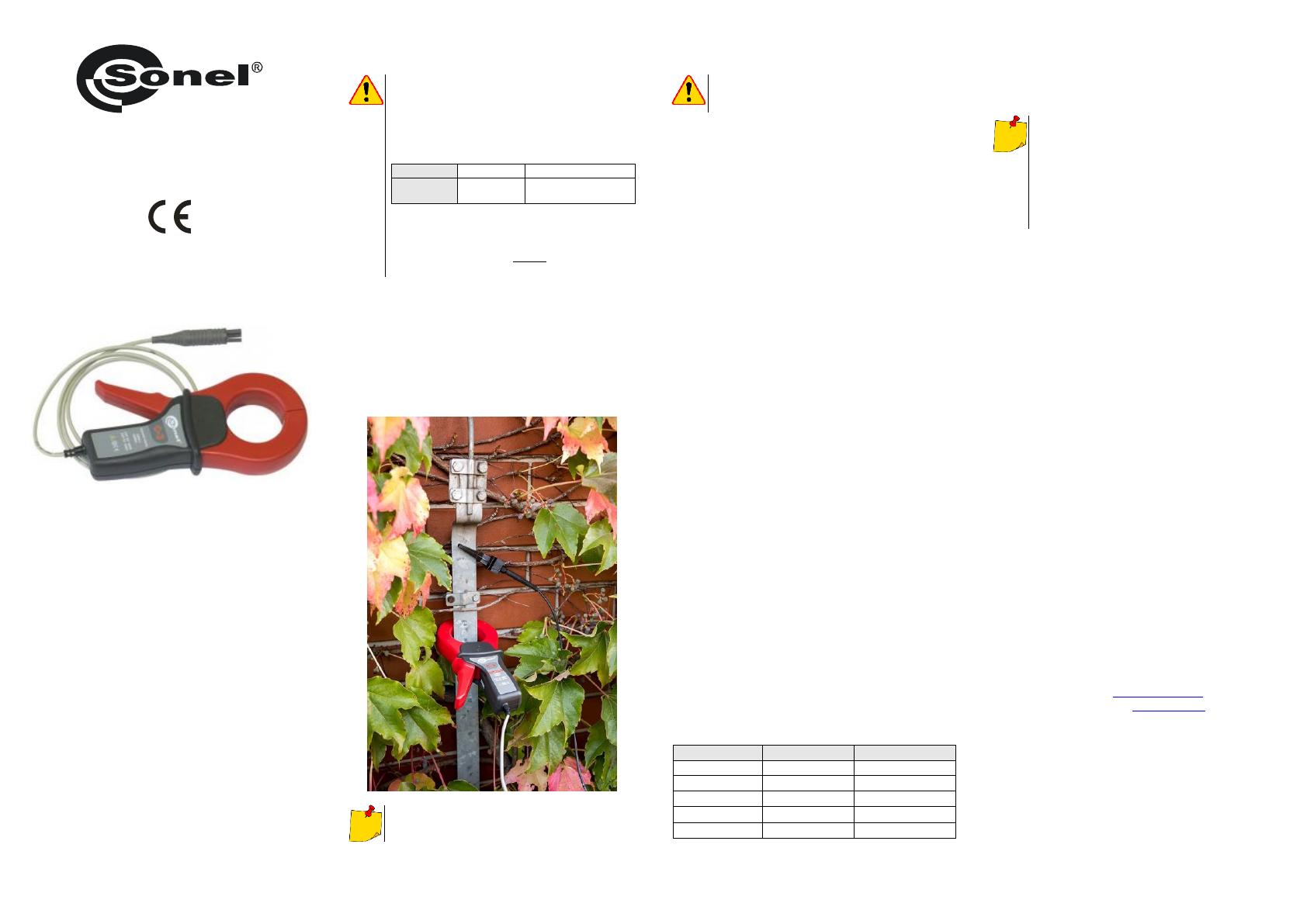
[kHz] f A1000
.
kont
I
3 Verwendung
Backen der Messzange öffnen, dabei den Lei-
ter mit den Backen umfassen und den Leiter in
Bezug auf die Backen ungefähr zentrieren, um
den Strom zu messen. Dann die Zange schließen
und sich vergewissern, dass beide Backen fest
aneinander anliegen.
Der Spalt (gebildet durch die Stirnflächen des
Kerns) sollte vollkommen sauber gehalten werden.
4 Wartung und Reinigung
ACHTUNG!
Führen Sie nur Wartungsschritte durch wie in die-
ser Anleitung beschrieben durch.
Vor der Reinigung die Messzange vom zu
messenden Stromkreis und vom Messgerät tren-
nen. Die Messzange nicht mit Wasser besprühen.
Staub mit einem weichen, trockenen Tuch vom
Spalt entfernen. Den zugänglichen Eisenteil der
Backen regelmäßig mit einem ölgetränkten Tuch
abwischen, um mögliche Korrosion zu vermeiden.
Die Messzange kann mit einem weichen,
feuchten Tuch und mit üblichen Reinigungsmitteln
gereinigt werden. Keine Lösungsmittel verwenden.
5 Zerlegen und Entsorgen
Ausgediente Elektronik und elektronisches Zu-
behör darf nicht zusammen mit gewöhnlichem
Hausmüll gesammelt werden, sondern muss ge-
trennt gehalten werden.
Bringen Sie diese zu den gesetzlich vorge-
schriebenen Sammelstellen für elektrisches und
elektronisches Zubehör.
Zerlegen Sie die Geräte nicht in Einzelteile,
bevor Sie es zum Entsorgen bringen.
Halten Sie die vorgeschriebenen Bestimmun-
gen zur Entsorgung von Verpackungen ein.
6 Referenzbedingungen
a) Temperatur ..............................................+20°C …+26°C
b) Relative Luftfeuchtigkeit .................................... 20…75%
c) Leiterposition .................... im Zentrum der Klemmbacken
d) Frequenz des Sinusstromes ............................ 48…65 Hz
e) THD............................................................................ <1%
f) Stromkonstantenkomponente .................................. keine
g) Permanentes magnetisches Feld ... <40 A/m (Erdmagnetfeld)
h) Variable des externen magnetischen Feldes ........... keine
i) Leiter in unmittelbarer Nähe .................... kein Stromfluss
7 Technische Daten
Grundlegende technische Daten
Strombereich
Genauigkeit 1)
Max. Phasenfehler
1 mA…100 mA
3% + 5 μA
nicht spezifiziert
0,1 A…1 A
2% + 3 μA
nicht spezifiziert
1 A…10 A
1%
2
10 A…100 A
0,5%
1
100 A…1200 A
0,3%
0,7
1) in % des gemessenen Wertes
a) Messbereich .............................................. 0…1000 A AC
b) Frequenzbereich ......................................... 30 Hz...5 kHz
c) Ausgangssignal ............................................... 1 A/1000 A
d) Maximale Ausgangsleistung ................................. 1 A AC
Bei Verwendung von der Messzange mit dem
Messgerät von SONEL ist die Gesamtgenauig-
keit des Messsystems (Messgerät + Messzan-
ge) in der Bedienungsanleitung des jeweiligen
Messgeräts angegeben.
Die Genauigkeit der Zange, die in diesem Be-
dienungsanleitung angegeben ist, ist nicht die
Summe aus Messgerätgenauigkeit und Zangen-
genauigkeit.
Weitere technische Daten
a) Isolierklasse gem. IEC 61010-1 ............................ doppelt
b) Messkategorie gem. IEC 61010-1 ...................... III 600 V
c) Schutzklasse gem. IEC 60529
geschlossene Backen ............................................. IP40
offene Backen ......................................................... IP30
d) Brandklasse nach UL 94 .............................................. V0
e) Abmessungen ................................... 216 × 111 × 45 mm
f) Gewicht .............................................................. ca. 550 g
g) Öffnungsweite Zangenbacken ............................... 53 mm
h) Höhe offener Zangenbacken ...............................139 mm
i) Maximaler Durchmesser der zu testenden Leitungen .........
............................................................................ 52 mm
j) Länge der Zangenleitungen ..................................... 2,0 m
k) Betriebstemperatur .................................... -10C…+55C
l) Relative Luftfeuchtigkeit .......................................... <90%
m) Höhe über n.N. ................................................... ≤2000 m
n) Elektromagnetische Verträglichkeit...................................
................... IEC 61000-6-3, IEC 61000-6-2, IEC 61326-1
8 Hersteller
Getehersteller für Garantieansprüche und Service:
SONEL S.A.
Wokulskiego 11
58-100 Świdnica
Polen
tel. +48 74 858 38 60
fax +48 74 858 38 09
E-mail: expo[email protected]
Web page: www.sonel.pl
Hergestellt in Frankreich für SONEL S.A.
  • Page 1 1
  • Page 2 2
  • Page 3 3
  • Page 4 4

Sonel MRU-200-GPS Instrukcja obsługi

Typ
Instrukcja obsługi
Ten podręcznik jest również odpowiedni dla