AAT NVIP-2Q-4201/PIR/W Instrukcja obsługi
- Kategoria
- Kamery ochrony
- Typ
- Instrukcja obsługi

Quick sta rt gu i de
NVIP-2Q-4201/PIR/W

NVIP-2Q-4201/PIR/W Quick start guide version 1.2
All rights reserved © AAT SYSTEMY BEZPIECZEŃSTWA sp. z o.o.
2
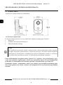
IMPORTANT SAFEGUARDS AND WARNINGS
THE PRODUCT MEETS THE REQUIREMENTS CONTAINED IN THE FOLLOWING
DIRECTIVES:
Information
The device, as a part of professional CCTV system used for surveillance and control, is not designed
for self installation in households by individuals without technical knowledge.
Excluding of responsibility in case of damaging data on a disk or other devices:
The manufacturer does not bear any responsibility in case of damaging or losing data on a disk or other
devices during device operation.
WARNING!
PRIOR TO UNDERTAKING ANY ACTION THAT IS NOT DESCRIBED FOR THE GIVEN
PRODUCT IN USER’S MANUAL AND OTHER DOCUMENTS DELIVERED WITH THE
PRODUCT, OR IF IT DOES NOT ARISE FROM THE USUAL APPLICATION OF THE
PRODUCT, MANUFACTURER MUST BE CONTACTED UNDER THE RIGOR OF EXCLUDING
THE MANUFACTURER’S RESPONSIBILITY FOR THE RESULTS OF SUCH AN ACTION.
DIRECTIVE 2014/30/EU OF THE EUROPEAN PARLIAMENT AND OF THE
COUNCIL of 26 February 2014 on the harmonization of the laws of the Member States
relating to electromagnetic compatibility (OJ L 96, 29.3.2014, p. 79 - 106, with changes)
DIRECTIVE 2012/19/EU OF THE EUROPEAN PARLIAMENT AND OF THE
COUNCIL of 4 July 2012 on waste electrical and electronic equipment (WEEE) (OJ L 97,
24.7.2012, p. 38 - 71,with changes)
DIRECTIVE 2011/65/EU OF THE EUROPEAN PARLIAMENT AND OF THE
COUNCIL of 8 June 2011 on the restriction of the use of certain hazardous substances in
electrical and electronic equipment (OJ L 174, 1.7.2011, p. 88 - 110, with changes)

NVIP-2Q4201/PIR/W Quick start guide version 1.2
All rights reserved © AAT SYSTEMY BEZPIECZEŃSTWA sp. z o.o.
3
IMPORTANT SAFEGUARDS AND WARNINGS
WARNING!
THE KNOWLEDGE OF THIS MANUAL IS AN INDESPENSIBLE CONDITION OF A PROPER DEVICE
OPERATION. YOU ARE KINDLY REQUSTED TO FAMILIRIZE YOURSELF WITH THE MANUAL
PRIOR TO INSTALLATION AND FURTHER DEVICE OPERATION.
WARNING!
USER IS NOT ALLOWED TO DISASSEMBLE THE CASING AS THERE ARE NO USER-
SERVICEABLE PARTS INSIDE THIS UNIT. ONLY AUTHORIZED SERVICE PERSONNEL MAY OPEN
THE UNIT.
INSTALLATION AND SERVICING SHOULD ONLY BE DONE BY QUALIFIED SERVICE PERSONNEL
AND SHOULD CONFORM TO ALL LOCAL REGULATIONS.
IMPORTANT SAFEGUARDS AND WARNINGS
1. Prior to undertaking any action please consult the following manual and read all the safety and operating
instructions before starting the device.
2. Please keep this manual for the lifespan of the device in case referring to the contents of this manual is
necessary;
3. All the safety precautions referred to in this manual should be strictly followed, as they have a direct
influence on user’s safety and durability and reliability of the device;
4. All actions conducted by the servicemen and users must be accomplished in accordance with the user’s
manual;
5. The device should be disconnected from power sources during maintenance procedures;
6. Usage of additional devices and components neither provided nor recommended by the producer is forbidden;
7. Mounting the device in places where proper ventilation cannot be provided (e. g. closed lockers etc.) is not
recommended since it may lead to heat build-up and damaging the device itself as a consequence;
8. Mounting the camera on unstable surface or using not recommended mounts is forbidden. Improperly
mounted camera may cause a fatal accident or may be seriously damaged itself. The camera must be mounted
by qualified personnel with proper authorization, in accordance with this user’s manual.
9. Device should be supplied only from a power sources whose parameters are in accordance with those
specified by the producer in the camera technical datasheet. Therefore, it is forbidden to supply the camera
from a power sources with unknown parameters, unstable or not meeting producer’s requirements;
10. Signal cables (conducting TV or / and telemetric signal) should be placed in a way excluding the possibility
of damaging them by accident. Special attention must be paid to cables getting from the camera and
connecting the power supply;
11. To avoid equipment damage, whole TV circuit should be equipped with properly made discharge-, overload-
and lightning protection devices. Usage of separating transformers is advised;
12. Electric installation supplying the device should be designed to meet the specifications given by the producer
in such a way that overloading is impossible;
13. User cannot repair or upgrade the equipment himself. All maintenance actions and repairs should be
conducted only by qualified service personnel;
14. Unplug the camera from the power source immediately and contact the proper maintenance department
when the following occurs:
• Damages to the power cord or to the plug itself;
• Liquids getting inside the device or exposure to strong mechanical shock;
• Device behaves in a way not described in the manual and all adjustments approved by the
manufacturer and possible to apply by user himself, seem not to have any effect;
• Camera or its casing is damaged;
• Atypical behaviour of the camera components can be seen (heard).
15. In necessity of repairs attention to using only original replacement parts (with their parameters in accordance
with those specified by the producer) should be paid. Non-licensed service and non-genuine replacement
parts may cause fire or electric shock.

NVIP-2Q-4201/PIR/W Quick start guide version 1.2
All rights reserved © AAT SYSTEMY BEZPIECZEŃSTWA sp. z o.o.
4
TABLE OF CONTENTS
1. FOREWORD INFORMATION ................................................................................... ..5
1.1. General characteristics ......................................................................................... 5
1.2. Technical specification .................................................................................... ...6
1.3. Camera dimension ........................................................................................... ...8
1.4. Package contents ............................................................................................... ...8
2. START-UP AND INITIAL CAMERA CONFIGURATION ...................................... 9
2.1. Description of camera components and connectors ............................................ 9
2.2. Power supply connection ..................................................................................... 9
2.3. Connection of alarm input/output ...................................................................... 10
2.4. Connecting the LAN network cable .................................................................. 11
2.5. Camera mounting .............................................................................................. 11
2.6. Starting the camera ............................................................................................ 12
2.6.1. Starting with connecting the camera to a wired LAN network ............... 12
2.6.1.1. Configuring network settings using a DHCP server ..................... 13
2.6.1.2. Manual configuration of network settings ..................................... 13
2.6.2. Starting with connecting the camera to a WiFi network ......................... 13
2.7. Security recommendations for network architecture and configuration............ 16
3. CONNECTING FROM A PC WITH A WEB BROWSER ....................................... 17
3.1. First connection to the camera ............................................................................ 17
3.2. Login screen ....................................................................................................... 18
3.3. Remote view window ......................................................................................... 18
4. CONNECTION FROM A DEVICE EQUIPPED WITH ANDROID SYSTEM ..... 20
5. RESTORING FACTORY SETTINGS ........................................................................ 20
5.1. Software factory reset ......................................................................................... 20
5.2. Hardware factory reset ...................................................................................... 20
TABLE OF CONTENTS

NVIP-2Q4201/PIR/W Quick start guide version 1.2
All rights reserved © AAT SYSTEMY BEZPIECZEŃSTWA sp. z o.o.
5
1. FOREWORD INFORMATION
1.1. General Characteristics
• Sensor resolution: 2 megapixels
• Mechanical IR cut filter, IR operation capability
• Min. Illumination from 0 lx with IR LED on
• Wide Dynamic Range (WDR) for enhanced image quality in diverse light conditions
• Digital Noise Reduction (DNR)
• Lens with remote focal and focus control, f=2.8mm/F=1.85
• Built-in LED illuminator: 12 pcs LED
• Compression of video stream: H.264/H265
• Max video processing resolution: 1920 x 1080
• Two independently configurable streams
• Stream parameters: compression, resolution, speed and quality defined individually for each video
stream
• RTP/RTSP protocol support for video transmission
• Two-way audio transmission
• Compression of audio stream: G.711
• Wireless WiFi and wired LAN connections
• Alarm input and output
• Hardware motion detection
• Build-in PIR detector
• Audio events detection
• Built-in webserver: camera configuration through the website
• Wide range of responses to alarm events: activation of alarm output , storage on memory card
• Four privacy zones
• Power supply: 12VDC, PoE (Power over Ethernet 802.3af)
Information
The manufacturer reserves the right to printing errors and technical specifications changes
without prior notice.
FOREWORD INFORMATION

NVIP-2Q-4201/PIR/W Quick start guide version 1.2
All rights reserved © AAT SYSTEMY BEZPIECZEŃSTWA sp. z o.o.
6
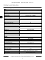
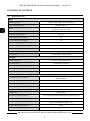
1.2. Technical specification
IMAGE
Image Sensor 2 MPX CMOS sensor 1/2.7” Galaxycore
Number of Eecve Pixels 1920 (H) x 1080 (V)
Min. Illuminaon
0.1 lx/F2.0 - color mode,
0 lx (IR on) - B/W mode
Electronic Shuer auto/manual: 1/5 s ~ 1/200000 s
Digital Slow Shuer (DSS) up to 1/5 s
Wide Dynamic Range (WDR) yes
Digital Noise Reducon (DNR) 3D
Defog Funcon (F-DNR) yes
Highlight Compensaon (HLC) yes
Back Light Compensaon (BLC) yes
LENS
Lens Type standard, f=2.8 mm/F1.85
DAY/NIGHT
Switching Type mechanical IR cut lter
Switching Mode auto, manual
Switching Delay 1 ~ 36 s
Switching Schedule yes
Visible Light Sensor yes
NETWORK
Stream Resoluon
1920 x 1080 (Full HD), 1280 x 960, 1280 x 720 (HD), 640 x 480 (VGA),
320 x 240 (QVGA)
Frame Rate 20 fps for each resoluon
Mulstreaming Mode 2 streams
Video/Audio Compression H.264, H.265/G.711
Number of Simultaneous Connecons max. 4
Bandwidth 8 Mb/s in total
Network Protocols Support HTTP, TCP/IP, IPv4, DHCP, DNS, DDNS, NTP, RTSP, RTP, P2P
ONVIF Protocol Support Prole S
Camera Conguraon
from Internet Explorer browser
languages: Polish, English, Russian, and others
Compable Soware NMS
Mobile applicaons RxCamView (iPhone, Android)
TECHNICAL SPECIFICATION

NVIP-2Q4201/PIR/W Quick start guide version 1.2
All rights reserved © AAT SYSTEMY BEZPIECZEŃSTWA sp. z o.o.
7
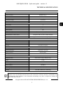
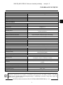
The declared range of WiFi network operation is based on laboratory tests and relates to open spaces. It
should be borne in mind that materials used for the construction of houses and flats, wall thickness and
electromagnetic field conditions in the immediate surroundings, may have an impact on limiting the
range of the WiFi network.
WIFI
Network standard IEEE802.11b, g, n
Band 2.4GHz
Security WEP, WPA-PSK/WPA2-PSK
Transmission range up to 50 m
Antenna built-in, omnidireconal
OTHER FUNCTIONS
Privacy Zones 4
Moon Detecon yes
PIR detector range up to 7 m
Audio Detecon yes
Image Processing 180˚ image rotaon, vercal ip, horizontal ip
Prealarm/Postalarm up to 5 s/up to 300 s
System Reacon to Alarm Events saving le on SD card, alarm output acvaon
Determent high power white LED, acousc signaling device
IR LED
LED Number 12
Range 10 m
Angle 120°
Smart IR yes (soware support)
INTERFACES
Audio Input/Output built-in microphone, speaker
Alarm Input/Output 1 (NO/NC)/1 relay type
Network Interface
1 x Ethernet - RJ-45 interface, 10/100 Mbit/s
Wireless (WiFi)
Memory Card Slot microSD - capacity up to 128GB
INSTALLATION PARAMETERS
Dimensions (mm)
63 (W) x 106 (H) x 33 (L)
with bracket: 75 (W) x 120 (H) x 33 (L)
Weight 0.2 kg
Enclosure plasc, black and white, wall mount/base in-set included
Power Supply PoE, 12 VDC
Surge protecon TVS 4000 V
Power Consumpon 2 W, 3 W (IR on)
Operang Temperature -10°C ~ 45°C
Humidity max. 95%, relave (non-condensing)
TECHNICAL SPECIFICATION

NVIP-2Q-4201/PIR/W Quick start guide version 1.2
All rights reserved © AAT SYSTEMY BEZPIECZEŃSTWA sp. z o.o.
8
1.3. Camera dimensions
Dimensions are given in millimeters
1.4. Package contents
After you open the package make sure that the following elements are inside:
• IP camera
• Accessories bag
• Quick start guide
Before starting the device familiarize yourself with the description and the role of particular
inputs, outputs and adjusting elements that the device is equipped with. If you have any
problems understanding the manual, please contact the AAT. Self-assembly and commissioning
of the camera is possible, provided that the person has basic knowledge of computer networks
and the use of appropriate tools.
Caution:
If the device was brought from a location with lower temperature, please wait until it reaches the
temperature of location it is currently in. Turning the device on immediately after bringing it
from a location with lower ambient temperature is forbidden, as the condensing water vapour
may cause short-circuits and damage the device as a result.
START-UP AND INITIAL CONFIGURATION

NVIP-2Q4201/PIR/W Quick start guide version 1.2
All rights reserved © AAT SYSTEMY BEZPIECZEŃSTWA sp. z o.o.
9
2. START-UP AND INITIAL CONFIGURATION
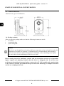
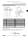
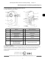
2.1. Description of camera components and connectors
2.2 Power supply connection
When powering the camera from an external 12VDC power supply, make sure that it has the correct
parameters and the power supply plug - the correct polarity. The use of a power source with
inappropriate parameters may result in incorrect operation or damage of the camera.
1 Microphone 10 Ventilation holes
2 Light sensor 11 LAN socket
3 Lens 12 Reset button
4 IR LEDs (infrared illuminator) 13 Loudspeaker/siren
5 PIR detector 14 Base
6 White LED 15 Memory card slot (on the side wall)
7 Alarm indicator 16 Block of alarm input/output connectors
8 Power indicator 17 12VDC power socket
9
Network connection indicator:
- flashing: no connection
- steady: connection established
18 Camera position adjustment
Center pin: +12V
GND
1
2
3
5
6
7
8
9
4
14
11
12
13
16
17
18
15
10
START-UP AND INITIAL CONFIGURATION

NVIP-2Q-4201/PIR/W Quick start guide version 1.2
All rights reserved © AAT SYSTEMY BEZPIECZEŃSTWA sp. z o.o.
10
The camera can also be powered via an RJ45 network connector, using PoE (IEEE 802.3af)
technology. Please, use a network switch or an IEEE 802.3af compliant PoE power supply to power
the camera through the PoE.
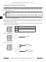
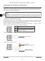
2.3. Connection of alarm input/output
The camera has one alarm input and output. The alarm input is used to connect a device such as a
motion detector, button, reed switch or photocell. Violation of the input triggers the alarm and activate
the previously programmed action.
The alarm output enables connection of an external siren and implementation of automatic control
functions, such as switching on lighting.
Alarm input connection
Alarm output connection
I
Alarm input, configurable: NC or NO
G
Alarm input ground
C
Alarm output terminals, (relay, 12VDC / 24VAC
2A max.)
O
trigger contact
signaling device
maximum load 2A
signaling device power
supply
12VDC or 24VAC max.
Caution:
It is forbidden to use – as the camera power source – PoE equipment (adapters, etc.) not
compatible with IEEE 802.3af standard (items called “passive PoE power supply”). Damages
that results from the usage of improper power supply source are not covered by the warranty.
START-UP AND INITIAL CONFIGURATION

NVIP-2Q4201/PIR/W Quick start guide version 1.2
All rights reserved © AAT SYSTEMY BEZPIECZEŃSTWA sp. z o.o.
11
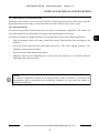
2.4. Connecting the LAN network cable
To connect to the camera via a wired LAN, insert the LAN cable plug into the LAN socket so that the
plug latch clicks into the socket. Connect the other end of the cable to your switch / router.
2.5 Camera mounting
The camera design allows flexible selection of the place of attachment / installation. The camera can
work when placed on any flat surface or be hung using mounting holes in the foot.
To mount the camera in a hanging position, we recommend you follow the following guidelines:
• Place the template where you want to install the camera. Then drill the holes according to the
template.
• Insert the dowels into the holes and tighten the screws. The screws should protrude a few
millimeters above the wall surface.
• Route and connect the cables to the camera.
• Hang the camera by the mounting base on the screws and make sure it is securely fastened.
Then adjust the camera position.
Caution:
The camera is designed for indoor use in living quarters. Using it outdoors, or in rooms with
high humidity such as swimming pools, bathrooms, laundries, etc. may cause the camera to
malfunction or damage.
START-UP AND INITIAL CONFIGURATION

NVIP-2Q-4201/PIR/W Quick start guide version 1.2
All rights reserved © AAT SYSTEMY BEZPIECZEŃSTWA sp. z o.o.
12
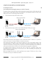
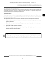
2.6. Starting the camera
2.6.1 Starting with connecting the camera to a wired LAN network
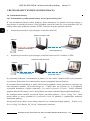
To start the camera, connect the Ethernet cable to the camera's network socket, and the other end to the
switch or router. If your switch or router is not a PoE device, you should also connect a 12VDC power
supply to the camera. The following schemes may help:
• Wired connection using a PoE switch or router:
• Wired connection using a switch or router without PoE and 12VDC power supply
After making connections and starting the camera (which takes about 2 minutes) it is possible to
connect to the camera. Use Internet Explorer to connect to the camera.
After entering the default address in the browser's address bar, wait for the installer window of the
"SurveillancePlugin.exe" add-on to appear. If the window does not appear and the browser displays the
connection error message "This page cannot be displayed", check the compatibility of the IP addresses
of the camera and the network in which it will work and make the appropriate configurations.
To configure network settings you will need the "Device Config Tool“ application, which can be
downloaded from the product page at www.novuscctv.com. After downloading and unpacking the
archive, install the application.
Before proceeding to the next part, read the application's user's manual, "IP4000 series Device Config
Tool Manual_EN_PL.pdf” attached to the archive.
.
PC
Camera
Data transmission
Switch or router with PoE
Power supply and data
transmission
Camera
PC
Data transmission
Switch or router without PoE
Data transmission
Power supply
START-UP AND INITIAL CONFIGURATION

NVIP-2Q4201/PIR/W Quick start guide version 1.2
All rights reserved © AAT SYSTEMY BEZPIECZEŃSTWA sp. z o.o.
13
• Połączenie wykorzystujące zewnętrzne zasilanie kamery i kabel ethernetowy
2.5. Konfiguracja parametrów przy użyciu przeglądarki internetowej
Domyślne ustawienia sieciowe dla kamery to:
1. Adres IP = 192.168.1.200
2. Maska sieci - 255.255.255.0
3. Brama - 192.168.1.1
4. Nazwa użytkownika - root
5. Hasło - pass
Znając adres IP kamery należy ustawić adres IP komputera w taki sposób aby oba urządzenia
pracowały w jednej podsieci (dla adresu IP kamery 192.168.1.200 jako adres IP komputera PC
możemy ustawić adres z zakresu 192.168.1.0 - 192.168.1.254, np.: 192.168.1.60). Niedopuszczalne jest
ustawianie adresu komputera takiego samego jak adres kamery.
Wykorzystując połączenie przez przeglądarkę internetową Internet Explorer lub oprogramowanie NMS
należy ustawić docelową konfigurację sieciową (adres IP, maskę sieci, bramę, serwery DNS)
lub włączyć tryb pracy DHCP pozwalający na pobranie adresu IP z serwera DHCP (wymagany jest
wówczas działający serwer DHCP). W przypadku korzystania z serwera DHCP należy upewnić się
co do długości okresu dzierżawy adresu IP, jego powiązania z adresem MAC kamery IP w celu
uniknięcia zmiany lub utraty adresu IP w czasie pracy urządzenia lub chwilowej awarii sieci / serwera
DHCP. Należy pamiętać że po zmianie adresu IP kamera zostanie zresetowana i trzeba wpisać nowy
adres w przeglądarce internetowej. Po konfiguracji ustawień sieciowych pozwalających na
bezkonfliktową pracę urządzenia, kamerę IP możemy podłączyć do sieci docelowej.
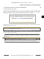
2.6.1.1 Configuring network settings using a DHCP server
After launching the application and searching for the camera, check the box next to its address. Enter
the login details in the network settings change panel, select "DHCP" in the "Net mode" window (leave
the other fields blank) and press the "Modify" button. After a while, the camera will start with the new
IP address given by the DHCP server built into the router/switch.
2.6.1.2 Manual configuration of network settings
We check the IP address in the computer's network settings. Then select a new IP address for the
camera, check if it is not busy (eg using the "ping" command at the command prompt) and change the
camera address in the application. After a while, the camera will start with the new IP address assigned.
After changing the camera's IP address, you should be able to connect to it using Internet Explorer.
Further configuration of the camera is carried out via its web panel (see chapter 3 on page 15).
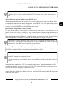
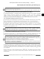
2.6.2 Starting with connecting the camera to a WiFi network
Startup is performed using a device with the Android or iOS operating system. Before starting, the
RXCamView application must be downloaded and installed on the device.
Startup begins by connecting a 12VDC power supply to the camera. Then wait until the green LED
starts flashing, signaling readiness to connect via WiFi. Then run the RXCamView application, go to
the device list and touch the sign to add a new device.
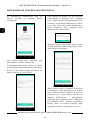
A list of options will appear, from which we select the option "CUBE". After selecting this item, a
scanner field will be displayed on the device's screen, which should be scanned with a QR code located
on the back of the camera.
+
Configuring the camera's IP address using a DHCP server is quick and convenient. However, at
a later stage of camera use it is recommended to set a static IP address in it. This will prevent
connection loss if the DHCP server changes the camera address.
The default camera network settings are:
IP address: 192.168.1.200, network mask: 255.255.255.0, login details: login - root, password -
pass
START-UP AND INITIAL CONFIGURATION
Do not connect the RJ45 network cable. Connecting a network cable disables the WiFi network.
The startup process will be shown on the example of the RXCamView application version 2.0.9
(build 002), installed on an Android 9 device.
It is not necessary to have an internet connection to run the camera.
It may be necessary to turn off cellular data on some mobile devices, for the duration of the boot
process.

NVIP-2Q-4201/PIR/W Quick start guide version 1.2
All rights reserved © AAT SYSTEMY BEZPIECZEŃSTWA sp. z o.o.
14
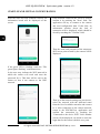
After the code has been scanned correctly, an
information board will be displayed on the
screen.
If the green LED is flashing, touch the "The
green light is flashing" confirmation box.
In the next step, indicate the WiFi network in
which the camera will work and enter the
password for it. This data will be sent to the
camera so that it can connect to the WiFi
network.
If the network visible on the screen is correct,
confirm it by touching the "Next" field. The
application will try to connect to the camera
and send configuration data. If this fails, an
information window about the lack of
connection will be displayed, which should be
closed by touching the "Confirm" field.
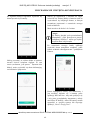
Then the name and password of the temporary
WiFi access point created by the camera will be
displayed.
Then go to the network settings on your device,
select the network with the indicated name
from the list of available networks and connect
to it. After connecting to the camera network,
return to the RXCamView application and
confirm the connection by touching the
"Connected to the device WiFi" field. Another
screen will be displayed, on which we enter the
login data for the camera (default: root, pass).
START-UP AND INITIAL CONFIGURATION

NVIP-2Q4201/PIR/W Quick start guide version 1.2
All rights reserved © AAT SYSTEMY BEZPIECZEŃSTWA sp. z o.o.
15
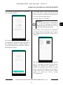
After entering the login details, the connecting
screen will be displayed.
Wait until the green LED on the camera lights
up continuously. During this time (especially if
the connection process is taking longer), a
screen indicating that the connection cannot be
established may appear.
You should ignore it and wait for the steady
green LED on the camera and for the next
screen to appear, in which you will be asked to
set a new password in the camera.
It can take about 1 to 2 minutes.
After setting a new password, the application
will display the device manager screen, where
the configured and connected camera will be
displayed.
The camera configuration process is completed
and it is possible to connect to the camera
through the RXCamView application. To
connect to it through a web browser, you must
know the camera's IP address. The IP address
of the camera can be checked in the router
options or using the „Device Config
Tool”application.
Attention:
Do not touch the "Done” confirmation
box, as this will interrupt the camera
configuration process and will need to
be performed from the beginning.
START-UP AND INITIAL CONFIGURATION

NVIP-2Q-4201/PIR/W Quick start guide version 1.2
All rights reserved © AAT SYSTEMY BEZPIECZEŃSTWA sp. z o.o.
16
2.7. Security recommendations for network architecture and configuration
WARNING!
Below are shown security recommendations for network architecture and configuration of
CCTV systems that are connected to the Internet to reduce the risk of unauthorized interference
with the system by a third party.
1. Absolutely change the default passwords and user names (if the device gives this possibility) of
all applied network devices (recorders, cameras, routers, network switches, etc.) to the
severely complexity password. Use lowercase and uppercase letters, numbers, and special characters
if there is such possibility.
2. Depending on the available functionality in the order to restrict access to the used network devices at
the administrator account level, it is recommended to configure the users accounts accordingly.
3. Do not use DMZ function (Demilitarized zone) in your router. Using that function you open the
access to recorder system from the Internet on all ports, which gives possibility for an unauthorized
interference with the system.
Instead of DMZ use port forwarding redirect only the ports which are necessary for the performance
of the connection (detailed information about ports of communication in different models of recorders,
cameras, etc. can be found in the operating instructions).
4. Use routers with firewall function and make sure it is enabled and properly configured.
5. It is recommended to change the default network communication port numbers of used devices
if there is such possibility.
6. If used network devices has a UPnP feature and it is not used, turn it off.
7. If used network devices has a P2P feature and it is not used, turn it off.
8. If used network devices support HTTPS protocol for connection, it is recommended to use it.
9. If used network devices support IP filtering for authorized connections function, it is recommended
to use it.
START-UP AND INITIAL CONFIGURATION

NVIP-2Q4201/PIR/W Quick start guide version 1.2
All rights reserved © AAT SYSTEMY BEZPIECZEŃSTWA sp. z o.o.
17
3. CONNECTING FROM A PC WITH A WEB BROWSER
3.1. First connection to the camera
After connecting and configuring the camera, you can connect to it. Enter the camera's IP address in the
address bar of Internet Explorer. After the connection is established, a message will be displayed
informing you that there is no ActiveX add-on required for proper camera operation.
To download it, click on the “download” link. The “SurveillancePlugin.exe” download window will be
displayed. Click the “Run” button.
When the add-in installer window appears, click "Install" and install the add-in, following the
information displayed by the installer.
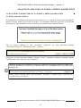
Installation of the add-on is one-time, it takes place during the first connection. However, on
subsequent connections, especially after changing the IP address, the browser may display a
security alert:
In this case, expand the options next to "Allow" button and select "Allow for all websites."
START-UP AND INITIAL CONFIGURATION

NVIP-2Q-4201/PIR/W Quick start guide version 1.2
All rights reserved © AAT SYSTEMY BEZPIECZEŃSTWA sp. z o.o.
18
WWW INTERFACE - WORKING WITH A CAMERA
3.2. Login screen
After connecting to the camera, the login screen will be displayed. Enter the login and password in
the login fields. You can also change the language of the camera interface.
The “Remember Password” option allows you to login to the camera without entering a password.
For security reasons, using this option is not recommended.
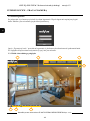
3.3. Remote view window
6 8
7
3
4
1
5
2

NVIP-2Q4201/PIR/W Quick start guide version 1.2
All rights reserved © AAT SYSTEMY BEZPIECZEŃSTWA sp. z o.o.
19
WWW INTERFACE - WORKING WITH A CAMERA
1. Stream selection buttons for display in the remote preview window
2. Preview window. Double-clicking the left mouse button on the preview window enables and disa-
bles the display of the image on the full screen.
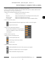
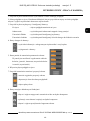
3. Buttons for selecting the operating mode and configure the camera:
Live - enables preview live stream
Playback - displays the playback panel of recordings from the memory card
Remote Setting - displays the configuration panel camera
Local Setting - displays the configuration panel of paths to snapshots folders
4. Icon to access to the camera:
5. Panel icon for setting image parameters:
The panel allows adjustment of image parameters
such as hue, brightness, contrast, color saturation
and sharpness.
6. Enable/disable live preview
7. Buttons to set the size and aspect ratio
8. Additional features control icons:
- displays information about the logged in user and the version of the applet
- logout from the camera
- sets the original aspect ratio
- fits the image to the browser window
- sets full screen
- enables and disables enlarge the picture
- enables and disables the record a video stream on your computer
- performs a screenshot and saves on your computer

NVIP-2Q-4201/PIR/W Quick start guide version 1.2
All rights reserved © AAT SYSTEMY BEZPIECZEŃSTWA sp. z o.o.
20
4. CONNECTION FROM A DEVICE EQUIPPED WITH ANDROID SYSTEM
To connect to the camera from an Android device, use the RXCamView application.
5. RESTORING FACTORY SETTINGS
5.1 Software factory reset
The camera allows to reset its settings to the factory defaults. To restore the camera settings, go to the
"Load Default" tab (Remote Setting -> Advanced -> Load Default). Then select the camera options and
functions whose settings you want to reset and press the "Save" button.
Resetting to factory settings is also possible with the "Device Config Tool" application.
After about 30 seconds you will be able to reconnect to the camera (on the current IP address, if the
network settings have not been reset, or on the default IP address).
5.2 Hardware factory reset
To reset the camera to the factory default settings, use the RESET button located on the back. Press and
hold it for about 5 seconds.
After about 30 seconds you will be able to reconnect to the camera at the default IP address.
CONNECTION FROM A DEVICE EQUIPPED WITH ANDROID SYSTEM
- enables and disables audio transmission from the camera to the computer
- enables and disables audio transmission from the computer to the camera
- turns the white LED on and off (warning light)
- turns the siren on and off
A description of all camera functions is included in the full user manual on the product page at
www.novuscctv.com
Strona się ładuje...
Strona się ładuje...
Strona się ładuje...
Strona się ładuje...
Strona się ładuje...
Strona się ładuje...
Strona się ładuje...
Strona się ładuje...
Strona się ładuje...
Strona się ładuje...
Strona się ładuje...
Strona się ładuje...
Strona się ładuje...
Strona się ładuje...
Strona się ładuje...
Strona się ładuje...
Strona się ładuje...
Strona się ładuje...
Strona się ładuje...
Strona się ładuje...
Strona się ładuje...
Strona się ładuje...
Strona się ładuje...
Strona się ładuje...
-
 1
1
-
 2
2
-
 3
3
-
 4
4
-
 5
5
-
 6
6
-
 7
7
-
 8
8
-
 9
9
-
 10
10
-
 11
11
-
 12
12
-
 13
13
-
 14
14
-
 15
15
-
 16
16
-
 17
17
-
 18
18
-
 19
19
-
 20
20
-
 21
21
-
 22
22
-
 23
23
-
 24
24
-
 25
25
-
 26
26
-
 27
27
-
 28
28
-
 29
29
-
 30
30
-
 31
31
-
 32
32
-
 33
33
-
 34
34
-
 35
35
-
 36
36
-
 37
37
-
 38
38
-
 39
39
-
 40
40
-
 41
41
-
 42
42
-
 43
43
-
 44
44


AAT NVIP-2Q-4201/PIR/W Instrukcja obsługi
- Kategoria
- Kamery ochrony
- Typ
- Instrukcja obsługi
w innych językach
- English: AAT NVIP-2Q-4201/PIR/W User manual
Powiązane artykuły
-
Novus NVIP-2H-4201 Instrukcja obsługi
-
-
-
-
-
-
-
-
-
Inne dokumenty
-
-
-
-
-
-
Blaupunkt HOS-X20 Instrukcja obsługi
-
Canon VB-S800VE Instrukcja obsługi
-
Grandstream GDS3710 Instrukcja obsługi
-
iGET SECURITY EP26 instrukcja
-
Wisenet XNV-6080RSA instrukcja