
Index
Contexts ................................................................ ………….Chapter – Page
1 Safety ........................................................................….............…………..…….1 - 1
1.01 Directives..........................……..................…......................................……..…...1 - 1
1.02 General notes on safety.........................…….….....................................………..1 - 1
1.03 Safety symbols.................................................................................……….…… 1 - 2
2 Proper use ……............................................................................…….....…...... 2 - 1
3 Specifications ………......................................................................……........... 3 - 1
3.01 GP-710-148, GP-724-108.......................................…....................................…. 3 - 1
3.02 Needles and threads …………...................................................…...…..........…. 3 - 2
3.03 Possible models and subclasses ………..........................................…..........….. 3 - 2
4 Explanation of symbols ……………...…........................................................... 4 - 1
5 Controls ……….................................................................................................. 5 - 1
5.01 Keys on machine head (only for machines with -D3/.. ) …………....................... 5 - 1
5.02 Bobbin thread monitoring with stitch counting ………….............…..................... 5 - 2
5.03 Pedal …......................................................................…....….............................. 5 - 2
5.04 Lever for lifting roller presser …………........................……................................. 5 - 3
5.05 Knee lever .................................................................…...................................... 5 - 3
5.06 Dey for seeting stitch length ……….................................................................. 5 - 4
5.07 Swing out roller presser ............................…..............................…..................... 5 - 4
6 Installation and commissioning ...................……………..........….........……... 6 - 1
6.01 Installation..................................……................................….............................. 6 - 1
6.01.01 Adjusting the table height.............................................…...…..............…......…. 6 - 1
6.02 Fitting the reel stand ...........................………….............................…................. 6 - 2
6.03 Tilted work base ..................................……................................…….............…. 6 - 3
6.04 Table top cutout ......................……..…............................................................ 6 - 4
6.05 Mounting the table top...............……………...............................…..................... 6 - 5
7 Preparation.........................................................…............................................ 7 - 1
7.01 Inserting the needle on model GP-710…............................................................ 7 - 1
7.02 Inserting the needle on model GP-724........................…………......................... 7 - 2
7.03 Winding the bobbin thread; adjusting the bobbin thread tension .........…........... 7 - 3
7.04 Removing/Inserting the bobbin case .......………………….................................. 7 - 4
7.05 Threading the bobbin case/Adjusting the bobbin thread tension ..................... 7 - 4
7.06 Threading the needle thread and regulating its tension on model GP-710……....7 - 5
7.07 Threading the needle thread and regulating its tension on model GP-724......... 7 - 6
7.08 Setting the stitch length ....................................................……….................…... 7 - 7
8 Care and maintenance .......................................………........…..................… 8 - 1 8.01
Checking/adjusting the air pressure....................................................................8 - 1
8.02 Cleaning the air filter of the air-filter/lubricator............... ...............................…..8 - 2 8.03
Cleaning ...............................................…......................…................................ 8 - 3
8.04 Oiling the hook ....................…....................…................................................... 8 - 4
8.05 Oil bowl for hook lubrication....….…….....……………………....…….................. 8 - 4
8.06 Filling the oil reservoir of the thread lubrication unit ..............………................. 8 - 5
8.07 Lubricating the bevel gears ............................................…………..................... 8 – 6
9 Adjustment ..............................………............................................................... 9 - 1
9.01 Notes on adjustment............................…............................................................ 9 - 1
www.garudan.cz

9.02 tools, gauges and other accessories........………………………………………......9 - 1
9.03 Adjusting the basic machine........……………….................................................. 9 - 2
9.03.01 Needle position in sewing direction on the GP-710……………….....……............9 - 2
9.03.02 Needle position in sewing direction on the GP-724…………...........…................ 9 - 3
9.03.03 Preliminary adjustment of the needle height……………………........................... 9 - 4
9.03.04 Needle rise, hook clearance, needle height and needle grard on the
H962 ..…………………………………………………………….……………….……..9 - 7
9.03.05 Needle rise, hook clearance, needle height and needle grard on the
H961 ..…………………………………………………………….……………….……..9 -9
9.03.06 Neelle position crosswise to sewing direction on the GP-724 …...…….......….. 9 - 12
9.03.07 Neelle position crosswise to sewing direction on the GP-710 ….........…........ 9 - 13
9.03.08 Height and stroke of the bobbin case opener .................................................... 9 - 14
9.03.09 Height of the feed wheel on the GP-724……............................................…...... 9 - 16
9.03.10 Height of the feed wheel on the GP-710............................................…..…....... 9- 17
9.03.11 Stitch length control enccentric ...............................…........…........................... 9 - 18
9.03.12 Stitch length scale disk...........................…........................................................ 9 - 19
9.03.13 Shaft crank to feed wheel drive...................…...................…..................…....... 9 - 20
9.03.14 Shaft crank to roller presser…….. ...........................…...................................... 9 - 21
9.03.15 Clearnce between roller presser and feed wheel ..............…………………....... 9- 22
9.03.16 Roller presser... ................................................................................................. 9 - 23
9.03.17 Stitch length on stitch length scale……….......................................................... 9 - 24
9.03.18 Synchronization of roller presser and feed wheel .......................……………............ 9 - 25
9.03.19 Retainer(only on model GP-724) ............…...................................................9 - 26
9.03.20 Knee lever ........................................................................................................ 9 - 27
9.03.21 Needle and tension release ..............................………….................................. 9 - 28
9.03.22 Thread check spring (GP-710) ...................…...............................9 - 29
9.03.23 Thread check springs (GP-724) .................................................................. 9 - 30
9.03.24 Bobbin winder .................……........................................................................... 9 - 31
9.03.25 Pressure of roller presser .................................................................................. 9 - 32
9.03.26 Lubrication .....................……………….............................................................. 9 - 33
9.03.27 Re-engage safety coupling ..........................................….................................. 9 - 34
9.04 Adjusting the edge trimmer-D........................................................……………...9 - 35
9.04.01 Resting position of the roller lever/radial position of the control cam .....…….... 9 - 35
9.04.02 Position of the thread catcher holder ................................................................ 9 - 36
9.04.03 Distance between thread catcher and needle plate …....................................... 9 - 37
9.04.04 Position of the thread catcher ................…….................................................... 9- 38
9.04.05 Knife position and knife pressure .........……...................................................... 9 - 39
9.04.06 Bobbin thread retaining spring .............……….................................................. 9 - 40
9.04.07 Manual cutting test ............……......................................................................... 9 - 41
9.04.08 Releasing the tension ...............................................…..................................... 9 - 42
9.04.09 Linkage rod (only for GP-724) ................…................................................. 9 - 43
9.05 Adjustment of backtacking mechanism-D3/.. .............................……………..... 9 - 44
9.05.01 Needle in the nendle hole(only for GP-710) ………………............…..........9 - 44
9.05.02 Coupling for roller presser drive ..................….................................................. 9 - 45
9.05.03 Bever gear s for feed wheel drive (on the GP-724) ….…............... 9 - 46
9.05.04 Bevel gear play(on the GP-724) ..........……..................…............. 9 - 47
9.05.05 Bevel gears for feed wheel drive (on the GP-710) ......….......….……............ 9 - 48
9.05.06 Bevel gear play(on the GP-710) ...……….......................................…............ 9- 49
www.garudan.cz

Safety
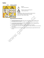
1.01 Safety symbols
Danger!
Points to be observed
Danger of injury for operating and
specialist personnel!
Caution
Do not operate without finger guard and safety devices.
B before threading,changing bobbin and needle,
cleaning etc. switch off main switch.
1.02 工作中的特殊
Important points for the user
● This Instruction Manual is a component of the machine and must be available to the
operating personnel at all times.
● The Instruction Manual must be read before operating the machine for the first time.
● The operating and specialist personnel must to be instructed in the safeguards of the
machine and safe work methods.
● It is the duty of the user to operate the machine in perfect running order.
● It is the obligation of the user to ensure that none of the safety mechanisms are removed or
deactivated.
● It is the obligation of the user to ensure that only authorized persons operate and work on the
machine.
www.garudan.cz

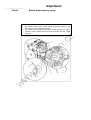
Safety
——————————
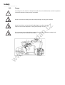
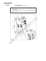
1.03 Danger
A working area of 1 meter is to be kept free both in front of and behind the machine in operation
so that the machine is always easily accessible.
Never reach into the sewing area while sewing! Danger of injury by the needle!
Never leave objects on the table while adjusting the machine settings!
Objects can become trapped or be slung away! Danger of injury!
Do not operate the machine without support1! Danger due to top-heavy sewing head!
Machine can tip over backwords when tilted!
www.garudan.cz

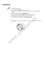
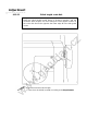
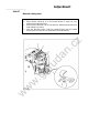
Safety
——————————
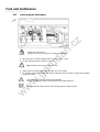
Switch the machine off before tilting it backwards!
Danger of injury if the machine is started accidently!
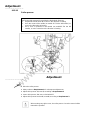
Do not operate the machine wihout its take-up-lever guard 2!
Danger of injury due to the motion of the take-up lever!
On machines with thread lubricator, only operate the machine with the eye guard 3 lowered!
The eye guard 3 protects the eyes from oil particles from the thread lubrication!
Do not operate the machine without belt guard 4!
Danger of injury by rotating drive belt!
Do not operate the machine without tilt lock 5!
Danger of crushing between sewing head and table top!
www.garudan.cz

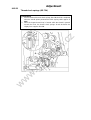
2 Proper use
GP-724-108 I s a double-needle, high-speed post bed sewing machine with driven feed
wheel and roller presser.
GP-710-148 Is a single needle, high-speed post bed sewing machine (post to the right of
the needle) with driven feed wheel and roller presser and synchronized
needle.
The machines are used for sewing lockstitch seams in the leather and upholstery industries.
Any use of these machines which is not approved by the manufacturer shall be
considered as improper use! The manufacturer shall not be liable for any damage
arising out of improper use! Proper use shall also be considered to include
compliance with the operation, adjustment, service and repair measures specified by
the manufacturer!
www.garudan.cz

3 Specifications
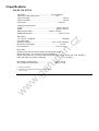
3.01 GP-710, GP724
Stitch type................................…...….....…...... 301 (lockstitch)
Clearacne under roller presser.....…………............. 7 mm
Clearance width .................... ................................................... 245 mm
Clearance height.............…....................................................... 115 mm
Post height ....................................................................... 180 mm
Sewing head dimensions
Length.........................…..................... ....................... approx. 615 mm
Width ................................................................…....... approx. 240 mm
Height (above table).......................….......... approx. 500 mm
Bedplate dimensions……..................................…............ 518 x 177 mm
Max.speed
GP-710, GP-724 Model …………................................ 3000spm◆
Connection data
Operating voltage................................................230 V ± 10%, 50/60 Hz
Max.power consumption ......................…........................... 1.2 kVA
Fuse protection .......................................…............... 1 x 16 A, insert
Noise data
Emission sound level at the work place at appropriate speed
DIN 45 635-48-A-1, ISO 11204, ISO 3744, ISO4871)
(Noise measurement in accordance with DIN 45 635-48-A-1, ISO 11204, ISO 3744, ISO4871)
H962 and H961 at a speed of 2400spm…………………….…..LpA = 79 dB(A) ■
Net weight of sewing head ........................... …........ approx. 61 kg
Gross weight of sewing head...........…...................... approx. 71 kg
▲ Subject to alteration
◆ Dependent on material, work operation and stitch length
■ KpA = 2,5 dB
www.garudan.cz

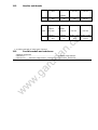
3.02 Needles and threads
▲ or similar strengths of other types of thread
3.03 Possible models and subclasses
Additional equipment
Subclass-D………………….…………………………………..Automatic edge trimmer
Subclass-D3…….Automatic edge trimmer, automatic presser foot lifter, backtacker.
(Nm)
GP-710 GP-724
1/100mm
40/3
90 134
134-35
Model
Thread
thickness ▲
(Nm) max.
Needle
thickness GP-710 GP-724
Synthetics 1/100mm Needle system
Needle system
40/3
90 134
134-35
www.garudan.cz

4 Explanation of symbols
In this instruction manual, work to be carried out or important information is accentuated by symbols which have the
following meanings:
Note, information
Cleaning, care
Lubrication
Maintenance, repairs, adjustment, servise work
(only to be carried out by technical staff)
www.garudan.cz

5 Controls
5.01 Keys on the machine head (only for machines with-D3)
● As long as key 1 is pressed
during sewing, the machine sews in reverse
direction.
● Keys 2 can be used for parameter settings,
Instruction manual of electronic control.
5.02 Bobbin thread monitoring with stitch counting
Machines without –D3/..
● About 100 stitches before reaching the preset
number of stitches, LED 1 Flashes.
● After the thread has been trimmed and the bobbin
changed, The stitch counting begins anew.
Presetting the number ofstitches, see
Instruction manual of electronic control.
5.03 Pedal
0 = Neutral position
1 = Sewing
2 = Raiser roller presser(on machines with-D3..)
3 = Trim sewing threads (on machines with-D..)
61-006
www.garudan.cz

5.04 Lever for lifting roller presser
● The roller presser can be raised by turning lever1.
5.05 Knee lever
● The roller presser can be raised by pressing the
knee lever 1 in the direction of the arrow.
5.06 Key for setting stitch length
● The stitch length is set by pressing key 1 and turning
the balance wheel (see Chapter 7.08 Setting the
stitch length).
www.garudan.cz

5.07 Swing out roller presser
● When the roller presser is raised, it can be swung
out by pulling it lightly downwards.
www.garudan.cz

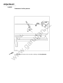
6 Installation and commissioning
The machine must only be installed and commissioned by qualified personnel!
All relevant safety regulations must be strictly adhered to!
If the machine is delivered without a table, be sure to use a stand and table top that can hold the
weight of the machine with its motor.
It is very important to ensure that the stand of the machine is firm and steady, also during
sewing.
6.01 Installation
The site where the machine is installed must be provided with suitable connections for electric
current.
It must be ensured that the standing surface of the machine site is firm and horizontal, and that
sufficient lighting is provided for.
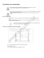
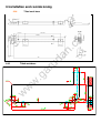
For packing and transportation reasons the table top is in the lowered position. The
table height is adjusted as described below.
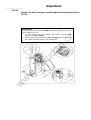
6.01.01 Adusting the table height
● Loosen screws 1and 2 and set the table height as required.
● Firmly tighten screw 1.
● Set the required pedal position and tighten screw 2
www.garudan.cz

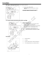
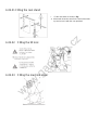
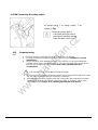
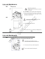
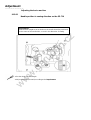
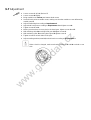
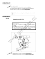
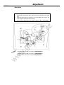
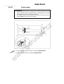
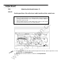
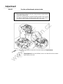
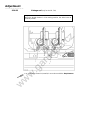
6.02.01 Fitting the reel stand
l Fit the reel stand as shown in Fig.
● Afterwards insert the stand in the hole of the table
top and secure it with the nuts provided.
6.02.02 Fitting the tilt lock
6.02.03 Fitting the machine cover
www.garudan.cz

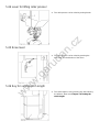
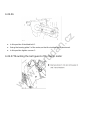
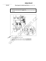
6.02.04 Mounting the flange motor to the bearing plate
6.02.05 Mounting the flange motor to the machine
www.garudan.cz

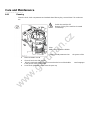
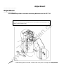
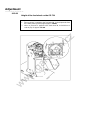
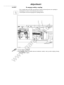
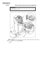
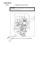
6.02.06
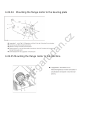
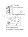
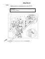
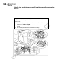
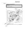
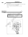
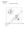
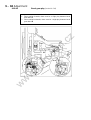
6.02.07 Mounting the belt guard of the flange motor
● In this position fit toofhed belt 1.
● Swing the bearing plate 2 of the motor,so that the toothed belt is tensioned.
● In this position tighten screws 3.
www.garudan.cz

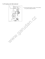
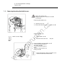
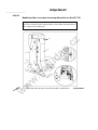
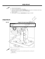
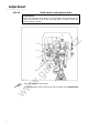
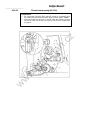
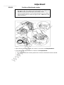
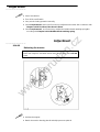
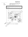
6.02.08 Connecting the safety switch
6.01 Commissioning
6.02
● Check the machine, particularly the electrical wriring for any damage.
● Clean the machine thoroughtly and then oil it or fill oil in (see Chapter 11 Care and
maintenance).
● Have a mechanic check whether the motor of the machine can be operated with the
available power supply, and that the motor is correctly connected in the junction box. If
there are any discrepancies. the machine must not be operated under any
circumstances.
The machine only be connected to an earthed socket!
● When the machine is running, the balance wheel must turn towards the operator.If it does
not, the motor connection must be changed by a mechanic.
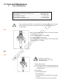
● Machines with pneumatic equipment must be connected to the compressed air supply.
The pressure gauge should indicate a pressure of 6 bar. If necessary, adjust to the
correct setting (see Chapter 11.07 Checking adjusting the air pressure).
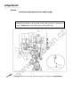
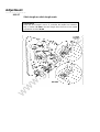
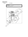
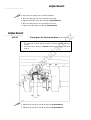
●Connect plug 1 of safety switch 2 as
shown in Fig.
When the sewing head is
tilted back,the safety switch
prevents the machine starting
when the main switch is on.
www.garudan.cz

6 Installation and commisioning
6.04 Tilted work base
6.05 Tilted work base
6-4
www.garudan.cz

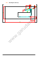
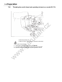
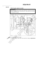
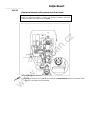
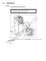
6.06 Mounting the table top
www.garudan.cz

Preparation
——————————
7 Setting up
All instructions and regulations in this instrution manual must be
observed .
Special attention must be paid to all safety regulations!
All setting-up work must only be carried out by personnel with the appropriate training.
For all setting-up work the machine must be disconnected from its power supply by
turning off the on/off switch, or
removing the plug from the electric power socket.
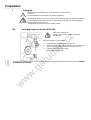
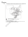
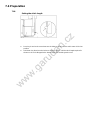
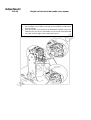
7.01 Inserting needle on model GP710-108
Switch the machine off!
Danger of injury if the machine is started
accidentally!
Only use needles of system 134
● Raise the roller presser 1 and swing it out.
● Loosen screw 2 and insert the needles as far as possible.
The long groove must face to left on model GP-710.
● Tighten screw 2 and swing roller
presser 1 back to position.
The Choice of needle depends on the model of the machine and the thread and material used (see Chapter
3.02 Needles and threads).
www.garudan.cz
Strona jest ładowana ...
Strona jest ładowana ...
Strona jest ładowana ...
Strona jest ładowana ...
Strona jest ładowana ...
Strona jest ładowana ...
Strona jest ładowana ...
Strona jest ładowana ...
Strona jest ładowana ...
Strona jest ładowana ...
Strona jest ładowana ...
Strona jest ładowana ...
Strona jest ładowana ...
Strona jest ładowana ...
Strona jest ładowana ...
Strona jest ładowana ...
Strona jest ładowana ...
Strona jest ładowana ...
Strona jest ładowana ...
Strona jest ładowana ...
Strona jest ładowana ...
Strona jest ładowana ...
Strona jest ładowana ...
Strona jest ładowana ...
Strona jest ładowana ...
Strona jest ładowana ...
Strona jest ładowana ...
Strona jest ładowana ...
Strona jest ładowana ...
Strona jest ładowana ...
Strona jest ładowana ...
Strona jest ładowana ...
Strona jest ładowana ...
Strona jest ładowana ...
Strona jest ładowana ...
Strona jest ładowana ...
Strona jest ładowana ...
Strona jest ładowana ...
Strona jest ładowana ...
Strona jest ładowana ...
Strona jest ładowana ...
Strona jest ładowana ...
Strona jest ładowana ...
Strona jest ładowana ...
Strona jest ładowana ...
Strona jest ładowana ...
Strona jest ładowana ...
Strona jest ładowana ...
Strona jest ładowana ...
Strona jest ładowana ...
Strona jest ładowana ...
Strona jest ładowana ...
Strona jest ładowana ...
Strona jest ładowana ...
Strona jest ładowana ...
Strona jest ładowana ...
Strona jest ładowana ...
Strona jest ładowana ...
Strona jest ładowana ...
Strona jest ładowana ...
-
 1
1
-
 2
2
-
 3
3
-
 4
4
-
 5
5
-
 6
6
-
 7
7
-
 8
8
-
 9
9
-
 10
10
-
 11
11
-
 12
12
-
 13
13
-
 14
14
-
 15
15
-
 16
16
-
 17
17
-
 18
18
-
 19
19
-
 20
20
-
 21
21
-
 22
22
-
 23
23
-
 24
24
-
 25
25
-
 26
26
-
 27
27
-
 28
28
-
 29
29
-
 30
30
-
 31
31
-
 32
32
-
 33
33
-
 34
34
-
 35
35
-
 36
36
-
 37
37
-
 38
38
-
 39
39
-
 40
40
-
 41
41
-
 42
42
-
 43
43
-
 44
44
-
 45
45
-
 46
46
-
 47
47
-
 48
48
-
 49
49
-
 50
50
-
 51
51
-
 52
52
-
 53
53
-
 54
54
-
 55
55
-
 56
56
-
 57
57
-
 58
58
-
 59
59
-
 60
60
-
 61
61
-
 62
62
-
 63
63
-
 64
64
-
 65
65
-
 66
66
-
 67
67
-
 68
68
-
 69
69
-
 70
70
-
 71
71
-
 72
72
-
 73
73
-
 74
74
-
 75
75
-
 76
76
-
 77
77
-
 78
78
-
 79
79
-
 80
80


Garudan GP-710-148 Instrukcja obsługi
- Typ
- Instrukcja obsługi
- Ten podręcznik jest również odpowiedni dla
w innych językach
- English: Garudan GP-710-148 User manual
Powiązane dokumenty

Inne dokumenty
-
 T & S Brass & Bronze Works EW-9095 Karta katalogowa
-
ELNA EXCELLENCE 780 Instrukcja obsługi
-
-
Alfa Network Next 40 Instruction book
-
JANOME 1600P Instrukcja obsługi
-
-
-
Everbilt HDS75 Instrukcja obsługi
-
Chicago Pneumatic Lubricator 43 Instrukcja obsługi
-
LIVARNO 430596 Instrukcja obsługi
