
Erweiterungsmodul EM 191
Expansion module EM EM 191
Module d’extension EM 191
Uitbreidingsmodule EM 191
Moduł rozszerzający EM 191
Дополнительный модуль EM 191
DGBFNLPLRUS
Handbuch für Einbau und Bedienung
Manual for installation and operation
Manuel de l’utilisateur : Montage et service
Montage- en bedieningshandleiding
Podręcznik montażu i obsługi
Руководство по монтажу и эксплуатации

2 Handbuch für Einbau und Bedienung, Erweiterungsmodul EM 191 D (#96501)
2. Inhaltsverzeichnis
Vorsicht!
Gefahr von Personenschäden!
Hier folgen wichtige Sicherheits -
hinweise, die zur Vermeidung von
Personen schäden unbedingt
beachtet werden müssen!
Achtung!
Gefahr von Sachschäden!
Hier folgen wichtige Sicherheits-
hinweise, die zur Vermeidung von
Sachschäden unbedingt beachtet
werden müssen!
Hinweis / Tipp
Kontrolle
Verweis
i
Hinweise
1. Symbolerklärung . . . . . . . . . . . .2
2. Inhaltsverzeichnis . . . . . . . . . . . .2
3. Allgemeine Sicherheitshinweise 3
4. Produktübersicht . . . . . . . . . . . .5
5. Montage . . . . . . . . . . . . . . . . . . .5
5.1 Erweiterungsmodul montieren .5
5.2 Verkabelung des
Erweiterungsmoduls . . . . . . . .6
1. Symbolerklärung

Handbuch für Einbau und Bedienung, Erweiterungsmodul EM 191 D (#96501) 3
3. Allgemeine Sicherheitshinweise
Zielgruppe
Dieses Produkt darf nur von qualifiziertem und geschultem Fachpersonal montiert, angeschlossen und in
Betrieb genommen werden!
Qualifiziertes und geschultes Fachpersonal im Sinne dieser Beschreibung sind Personen
- mit Kenntnis der allgemeinen und speziellen Sicherheits- und Unfallverhütungsvorschriften,
- mit Kenntnis der einschlägigen elektro technischen Vorschriften,
- mit Ausbildung in Gebrauch und Pflege angemessener Sicherheitsausrüstung,
- mit ausreichender Unterweisung und Beaufsichtigung durch Elektrofachkräfte,
- mit der Fähigkeit, Gefahren zu erkennen, die durch Elektrizität verursacht werden können,
- mit Kenntnis in der Anwendung der EN 12635 (Anforderungen an Installation und Nutzung).
Gewährleistung
Für eine Gewährleistung in Bezug auf Funktion und Sicherheit müssen die Hinweise in dieser Anleitung
beachtet werden.
Bei Missachtung der Warnhinweise können Körperverletzungen und Sachschäden auftreten.
Für Schäden, die durch Nichtbeachtung der Hinweise eintreten, haftet der Hersteller nicht.
Um Einbaufehler und Schäden am Gerät zu vermeiden, ist unbedingt nach den Montage an weisungen der
Einbauanleitung vorzugehen. Das Produkt darf erst nach Kenntnisnahme der zugehörigen Einbau- und
Bedienungs anleitung betrieben werden.
Die Einbau- und Bedienungsanleitung ist dem Betreiber der Toranlage zu übergeben und aufzubewahren.
Sie beinhaltet wichtige Hinweise für Bedienung, Prüfung und Wartung.
Das Produkt wird gemäß den in der Hersteller- und Konformitäts erklärung aufgeführten Richtlinien und
Normen gefertigt. Das Produkt hat das Werk in sicherheitstechnisch einwandfreiem Zustand verlassen.
Kraftbetätigte Fenster, Türen und Tore müssen vor der ersten Inbetrieb nahme und nach Bedarf, jedoch
jährlich mindestens einmal von einem Sachkundigen geprüft werden (mit schriftlichem Nachweis).
Bestimmungsgemäße Verwendung
Das Erweiterungsmodul erweitert die Steuerung Control vario.
Neben den Hinweisen in dieser Anleitung sind die allgemein gültigen Sicherheits- und Unfall vor-
schriften zu beachten! Es gelten unsere Verkaufs- und Lieferbedingungen.
Bitte unbedingt lesen!

3. Allgemeine Sicherheitshinweise
Hinweise zum Einbau
• Stellen Sie sicher, dass sich die anzuschließenden Anlagen (Türen etc.) mechanisch in einem
einwandfreien Zustand befinden.
• Vor Verkabelungsarbeiten trennen Sie das System unbedingt von der Stromversorgung.
Stellen Sie sicher, dass während der Verkabelungsarbeiten die Stromversorgung unterbrochen bleibt.
• Beachten Sie die örtlichen Schutzbestimmungen.
• Verlegen Sie die Netz- und Steuerleitungen unbedingt getrennt. Die Betriebsspannung beträgt 24 V.
Hinweise zur Reinigung
Auf keinen Fall dürfen zur Reinigung eingesetzt werden: direkter Wasserstrahl, Hochdruckreiniger, Säuren
oder Laugen.
Bitte unbedingt lesen!
4 Handbuch für Einbau und Bedienung, Erweiterungsmodul EM 191 D (#96501)

Handbuch für Einbau und Bedienung, Erweiterungsmodul EM 191 D (#96501) 5
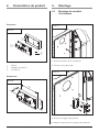
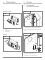
Lieferumfang
Abmessungen
1 Platine
2 Plaltinenträger
3 Schraube M4x12
1
4.1 / 1
2
4.1 / 2
69
38
26
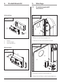
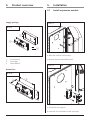
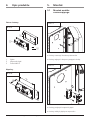
5.1 Erweiterungsmodul
montieren
5. Montage
• Öffnen Sie das Steuerungsgehäuse.
• Entfernen Sie die vormontierte Schraube.
5.1 / 1
4. Produktübersicht
3
• Schrauben Sie den Platinenträger auf.
• Setzen Sie die Platine in den Platinenträger ein.
5.1 / 2

Achtung!
Um die korrekte Funktion zu
gewährleisten, darf nur das
Marantec-Bus-System angeschlossen
werden (MS-Bus).
5. Montage
6 Handbuch für Einbau und Bedienung, Erweiterungsmodul EM 191 D (#96501)
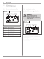
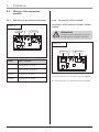
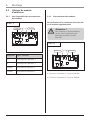
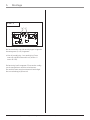
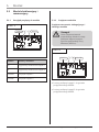
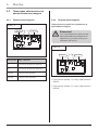
Bezeichnung
Art / Funktion
A LED Anzeige Antrieb 1
B LED Anzeige Antrieb 2
XW40A Anschluss Antrieb 1
XW40B Anschluss Antrieb 2
5.2 Verkabelung des
Erweiterungsmoduls
5.2.1 Übersicht der Modulanschlüsse 5.2.2 Anschluss der Module
• Schließen Sie den Antrieb 1 an die Anschluss-
buchse XW40A an.
• Schließen Sie den Antrieb 2 an die Anschluss-
buchse XW40B an.
5.2.2 / 1
5.2.1 / 1
Anschluss Bediensteuerung und weiteres
Modul
A
B
XW40B
XW40A
A
B
XW40B
XW40A

Handbuch für Einbau und Bedienung, Erweiterungsmodul EM 191 D (#96501) 7
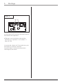
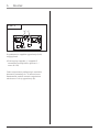
5. Montage
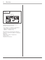
Nach Anschluss der Antriebe blinken die
Anzeigen (A+B) langsam.
• Führen Sie bei Antrieb 1 und bei Antrieb 2 ein
Reset der MS-Bus-Module durch (Ebene 1 /
Menü 8 / G8).
Die Steuerung benötigt ca. 30 Sekunden um
angeschlossene Module zu erkennen.
Der Modul-Reset wird automatisch beendet.
Die Anzeige (A) leuchtet.
5.2.2 / 2
A
B

8 Manual for installation and operation, Expansion module EM 191 GB (#96501)
2. Table of contents
Caution!
Danger of personal injury!
The following safety advice must be
observed at all times so as to avoid
personal injury!
Attention!
Danger of material damage!
The following safety advice must be
observed at all times so as to avoid
material damage!
Advice / Tip
Check
Reference
i
Advice
1. Meaning of symbols . . . . . . . . . .8
2. Table of contents . . . . . . . . . . . .8
3. General safety advice . . . . . . . . .9
4. Product overview . . . . . . . . . . .11
5. Installation . . . . . . . . . . . . . . . .11
5.1 Install expansion module . . . .11
5.2 Wiring of the
expansion module . . . . . . . . .12
1. Meaning of symbols

Manual for installation and operation, Expansion module EM 191 GB (#96501) 9
3. General safety advice
Target group
This operator system may only be installed, connected and put into operation by qualified and trained
professionals!
Qualified and trained specialist personnel are persons
- who have knowledge of the general and special safety regulations,
- who have knowledge of the relevant electro-technical regulations,
- with training in the use and maintenance of suitable safety equipment,
- who are sufficiently trained and supervised by qualified electricians,
- who are able to recognise the particular hazards involved when working with electricity,
- with knowledge regarding applications of the EN 12635 standard (installation and usage requirements).
Warranty
For an operations and safety warranty, the advice in this instruction manual has to be observed.
Disregarding these warnings may lead to personal injury or material damage. If this advice is disregarded,
the manufacturer will not be liable for damages that might occur.
To avoid installation errors and damage to the device, it is imperative that the installation instructions are
followed. The product may only be operated after reading these installation and operating instructions.
The installation and operating instructions are to be given to the door system user, who must keep them
safe. They contain important advice for operation, checks and maintenance.
This item is produced according to the directives and standards mentioned in the Manufacturer's
Declaration and in the Declaration of Conformity. The product has left the factory in perfect condition with
regard to safety.
Power-operated windows, doors and gates must be checked by an expert (and this must be documented)
before they are put into operation and thereafter as required, but at least once a year.
Correct use
The expansion module expands the Control vario control unit.
Beside the advice in these instructions, please observe the general safety and accident
prevention regulations! Our sales and supply terms and conditions are effective.
Please read carefully!

3. General safety advice
Installation tips
• Ensure that the devices to be connected (doors etc.) are in a mechanically faultless state.
• Before commencing cabling works it is very important to disconnect the system from the electricity supply.
Ensure that the electricity supply remains disconnected throughout the cabling works.
• Adhere to the local protection regulations.
• Lay the electricity supply cables and control cables; these MUST be laid separately.
The operating voltage is 24 V.
Information on cleaning the operator system
Never use water jets, high pressure cleaners, acids or bases for cleaning.
Please read carefully!
10 Manual for installation and operation, Expansion module EM 191 GB (#96501)

Manual for installation and operation, Expansion module EM 191 GB (#96501) 11
Supply package
Dimensions
1 Circuit board
2 Card cage
3 Screw M4x12
1
4.1 / 1
2
4.1 / 2
69
38
26
5.1 Install expansion module
5. Installation
• Open the control unit housing.
• Remove the pre-assembled screw.
5.1 / 1
4. Product overview
3
• Screw the card cage on.
• Insert the circuit board into the card cage.
5.1 / 2

Attention!
To ensure correct operation, only use
the Marantec bus system (MS bus).
5. Installation
12 Manual for installation and operation, Expansion module EM 191 GB (#96501)
Label Type / function
A LED indicator for drive 1
B LED indicator for drive 2
XW40A Connection of drive 1
XW40B Connection of drive 2
5.2 Wiring of the expansion
module
5.2.1 Overview of the module connections 5.2.2 Connection of the modules
• Connect drive 1 to connecting socket XW40A.
• Connect drive 2 to connecting socket XW40B.
5.2.2 / 1
5.2.1 / 1
Connection of the control unit and a further
module
A
B
XW40B
XW40A
A
B
XW40B
XW40A

Manual for installation and operation, Expansion module EM 191 GB (#96501) 13
5. Installation
After connecting the drive units, the indicators
(A+B) flash slowly.
• Carry out a reset of the MS bus modules
(Level 1 / Menu 8 / G8) for drive 1 and drive 2.
The control unit requires approx. 30 seconds to
recognise any modules connected to it.
The module reset ends automatically.
LED display (A) is on.
5.2.2 / 2
A
B

14 Manuel de l’utilisateur : Montage et service, Module d’extension EM 191 F (#96501)
2. Table des matières
Prudence !
Risque de dommages corporels !
Vous trouverez ici d’importantes
consignes de sécurité à observer
scrupuleusement pour éviter des
dommages corporels !
Attention !
Risque de dommages matériels !
Vous trouverez ici d’importantes
consignes de sécurité à respecter
scrupuleusement pour éviter des
dommages matériels !
Remarque / Conseil
Contrôle
Référence
i
Remarques
1. Explication des symboles . . . . .14
2. Table des matières . . . . . . . . . .14
3. Consignes générales de
sécurité . . . . . . . . . . . . . . . . . . .15
4. Présentation du produit . . . . . .17
5. Montage . . . . . . . . . . . . . . . . . .17
5.1 Montage du module
d'extension . . . . . . . . . . . . . .17
5.2 Câblage du module
d'extension . . . . . . . . . . . . . .18
1. Explication des symboles

Manuel de l’utilisateur : Montage et service, Module d’extension EM 191 F (#96501) 15
3. Consignes générales de sécurité
Groupe-cible
Ce produit doit être monté, raccordé et mis en service exclusivement par un personnel qualifié et instruit
qui :
- dispose de connaissances relatives aux directives spécifiques de sécurité et de prévention des accidents,
- dispose de connaissances sur les règles se rapportant à l’électrotechnique,
- dispose d’une formation aux premiers secours et à l’utilisation d’équipements de sécurité,
- est suffisamment instruit et encadré par des électriciens qualifiés,
- a la capacité de reconnaître les dangers liés à l’électricité,
- dispose de connaissances dans l’application de la norme EN 12635 (exigences concernant l’installation et
l’utilisation).
Garantie
La garantie concernant la fonctionnalité et la sécurité d’utilisation entrera en vigueur si les consignes
contenues dans ces instructions ont été respectées. La non-observation des présentes consignes peut
conduire à des blessures corporelles et des dégâts matériels. Le fabricant ne sera pas responsable des
dommages imputables à un non-respect des consignes.
Afin d'éviter toute erreur pouvant occasionner un endommagement de l’appareil, il convient de suivre
impérativement les indications de la notice de montage. .Le produit ne doit être mis en service qu’après
avoir pris connaissance du contenu de cette notice de montage et de service.
Les instructions de montage et de service sont à remettre à l’utilisateur de l’installation et à conserver.
Elles contiennent d’importantes informations concernant l’utilisation, les vérifications et la maintenance.
Le produit est fabriqué conformément aux normes et directives citées dans la déclaration de conformité
constructeur
et le certificat de conformité. Le produit a quitté l’usine dans un état de sécurité technique sans défauts.
Avant la première mise en service, les fenêtres, portes et portails motorisés doivent être vérifiés par un
spécialiste et entretenus au moins une fois par an et selon les besoins (avec justificatif écrit).
Application conforme
Le module d'extension élargit la commande Control vario.
En plus des consignes contenues dans ces instructions, il faut respecter les règlements généraux
sur la sécurité et sur la prévention des accidents ! Nos conditions générales de vente et de
livraison entrent en vigueur.
A lire absolument !

3. Consignes générales de sécurité
Consignes concernant le montage
• Vérifiez l'état mécanique irréprochable des installations à brancher (Portes etc.).
• Avant les travaux de câblage, il est indispensable de couper l’alimentation du système.
Pendant les travaux, l'alimentation électrique doit impérativement restée coupée.
• Respectez les normes locales de sécurité en vigueur.
• Pour éviter les phénomènes d'induction, il est impératif de séparer dans des gaines différentes les câbles
d'asservissement des câbles d'alimentation du moteur. La tension de service est de 24 V.
Consignes concernant l'entretien de l'opérateur
A proscrire : un jet d’eau direct, un nettoyeur haute pression, des acides ou une eau savonneuse.
A lire absolument !
16 Manuel de l’utilisateur : Montage et service, Module d’extension EM 191 F (#96501)

Manuel de l’utilisateur : Montage et service, Module d’extension EM 191 F (#96501) 17
Fourniture
Dimensions
1 Platine
2 Support de platines
3 Vis M4x12
1
4.1 / 1
2
4.1 / 2
69
38
26
5.1 Montage du module
d'extension
5. Montage
• Ouvriez le boîtier de la commande.
• Enlevez la vis prémontée.
5.1 / 1
4. Présentation du produit
3
• Ouvriez le support des platines.
• Mettez la platine dans le support des platines.
5.1 / 2

Attention !
Afin d'assurer un fonctionnement
correct, seul le système bus de
Marantec peut être raccordé
(Bus MS).
5. Montage
18 Manuel de l’utilisateur : Montage et service, Module d’extension EM 191 F (#96501)
Désignation
Type / Fonction
A Affichage DEL Opérateur 1
B Affichage DEL Opérateur 2
XW40A Branchement Opérateur 1
XW40B Branchement Opérateur 2
5.2 Câblage du module
d'extension
5.2.1 Vue d'ensemble des raccordements
des modules
5.2.2 Raccordement des modules
• Connectez l'opérateur 1 à la prise XW40A.
• Connectez l'opérateur 2 à la prise XW40B.
5.2.2 / 1
5.2.1 / 1
Raccordement de la commande fonctionnelle
et du module supplémentaire
A
B
XW40B
XW40A
A
B
XW40B
XW40A

Manuel de l’utilisateur : Montage et service, Module d’extension EM 191 F (#96501) 19
5. Montage
Les affichages (A+B) clignotent lentement après le
branchement des opérateurs.
• Effectuez une réinitialisation des modules
MS-BUS pour l'opérateur 1 et 2 (Niveau 1 /
Menu 8 / G8).
La commande a besoin de 30 secondes env. pour
reconnaître les modules connectés.
Le module Reset s'arrête automatiquement.
L'affichage (A) est allumé.
5.2.2 / 2
A
B

20 Installatie- en bedieningshandleiding, Uitbreidingsmodule EM 191 NL (#96501)
2. Inhoudsopgave
Voorzichtig!
Gevaar voor lichamelijk letsel!
Hier volgen belangrijke veiligheidsin-
structies die absoluut in acht moeten
worden genomen ter voorkoming
van lichamelijk letsel!
Attentie!
Gevaar voor materiële schade!
Hier volgen belangrijke veiligheidsin-
structies die absoluut in acht moeten
worden genomen ter voorkoming
van materiële schade!
Opmerking / Tip
Controle
Informatie
i
Aanwijzingen
1. Verklaring van de symbolen . .20
2. Inhoudsopgave . . . . . . . . . . . . .20
3. Algemene
veiligheidsinstructies . . . . . . . .21
4. Productoverzicht . . . . . . . . . . . .23
5. Montage . . . . . . . . . . . . . . . . . .23
5.1 Uitbreidingsmodule
monteren . . . . . . . . . . . . . . . .23
5.2 Bekabeling van de
uitbreidingsmodule . . . . . . . .24
1. Verklaring van de symbolen
Strona się ładuje...
Strona się ładuje...
Strona się ładuje...
Strona się ładuje...
Strona się ładuje...
Strona się ładuje...
Strona się ładuje...
Strona się ładuje...
Strona się ładuje...
Strona się ładuje...
Strona się ładuje...
Strona się ładuje...
Strona się ładuje...
Strona się ładuje...
Strona się ładuje...
Strona się ładuje...
Strona się ładuje...
Strona się ładuje...
Strona się ładuje...
Strona się ładuje...
-
 1
1
-
 2
2
-
 3
3
-
 4
4
-
 5
5
-
 6
6
-
 7
7
-
 8
8
-
 9
9
-
 10
10
-
 11
11
-
 12
12
-
 13
13
-
 14
14
-
 15
15
-
 16
16
-
 17
17
-
 18
18
-
 19
19
-
 20
20
-
 21
21
-
 22
22
-
 23
23
-
 24
24
-
 25
25
-
 26
26
-
 27
27
-
 28
28
-
 29
29
-
 30
30
-
 31
31
-
 32
32
-
 33
33
-
 34
34
-
 35
35
-
 36
36
-
 37
37
-
 38
38
-
 39
39
-
 40
40


w innych językach
- Deutsch: Marantec EM 191 Bedienungsanleitung
- français: Marantec EM 191 Le manuel du propriétaire
- English: Marantec EM 191 Owner's manual
- русский: Marantec EM 191 Инструкция по применению
- Nederlands: Marantec EM 191 de handleiding
Powiązane artykuły
-
Marantec EM 181 Instrukcja obsługi
-
-
-
-
Marantec EM 131 Instrukcja obsługi
-
Marantec Comfort 390 Instrukcja obsługi
-
-
Marantec Comfort 257.2 Instrukcja obsługi
-
-