
INSTALLATION AND OPERATION MANUAL
INSTALLATIONS-UND BEDIENUNGSANLEITUNG
MANUEL D’INSTALLATION ET D’UTILISATION
INSTALLAZIONE DI GEBRUIK VAN MANUA
INSTRUKCJA INSTALACJI I UŻYTKOWANIA
MANUAL DE INSTALARE ȘI UTILIZARE
FR
DE
EN
PL
RO
EURO PUMP UNIT

2
DEDE
ENEN
INDEX
EN
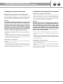
Thank you for trusting us and purchasing one of our products.
We ask that you read this manual carefully, which contains
all the specifications and all relevant information for proper
operation. The information contained in this manual can be
adjusted if necessary due to technical changes.
® All rights reserved. No part of the publication may be
reproduced or distributed without the written permission
of Purmo Group.
DEDE
Vielen Dank für Ihr Vertrauen und den Kauf eines unserer
Produkte. Wir bitten Sie, dieses Handbuch sorgfältig zu lesen,
das alle Spezifikationen und alle relevanten Informationen
für den ordnungsgemäßen Betrieb enthält. Die in diesem
Handbuch enthaltenen Informationen können bei Bedarf
aufgrund technischer Änderungen angepasst werden.
® Alle Rechte vorbehalten. Kein Teil der Publikation
darf ohne schriftliche Genehmigung der Purmo Group ver-
vielfältigt oder verbreitet werden.
1. BESCHREIBUNG ........................................ 3
1.1 Konstruktion
1.2 Technische Daten
2. INSTALLATION UND PRÜFUNG .............. 4
2.1 Installing
2.2 Einbau des Thermostatkopfes mit Kappilarfühler
2.3 Begrenzung der maximalen Temperatur
2.4 Füllen und Spülen
2.5 Anpassen der Anschlussseite
2.6 Entlüften und Einstellen der Pumpe
3. ABGLEICHEN UND EINSTELLEN
DES SYSTEMS .......................................... 6
3.1 Auslegungsbeispiel
3.2 Einstellen der Projekttemperatur
4. DAB EVOSTA 2 70/130 PUMPE...................8
4.1 Hinweise und Betriebsparameter
4.2 Einbaulagen
4.3 Entlüften der Pumpe
4.4 Einstellung der Regelkurven
1. DESCRIPTION .......................................... 3
1.1 Construction
1.2 Technical data
2. INSTALLATION AND TESTING.................4
2.1 Installing the unit
2.2 Installation of thermostatic head with capillary sensor
2.3 Limitation of the maximum temperature
2.4 Testing and filling
2.5 Adjusting the connection side
2.6 Venting and setting the pump
3. BALANCING AND SETTING
THE SYSTEM ............................................ 6
3.1 Design example
3.2 Adjusting the project temperature
4. DAB EVOSTA 2 70/130 PUMP .......................8
4.1 Notes and operating parameters
4.2 Installation position
4.3 Bleeding the pump
4.4 Adjusting the control curves

3
DEDE
ENEN
b
a
c
g
h
e
d
f
i
210
49
190
130
50
305
23
94
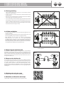
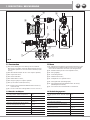
1. DESCRIPTION
/
BESCHREIBUNG
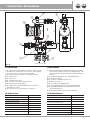
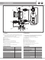
Fig. A
1.2 Technical data
Primary circuit maximum temperature : 90 °C
Maximum pressure: 10 bar
Primary circuit max ΔP: 1 bar
Secondary control range:
(thermostatic regulation) 20÷65 °C
Mixing unit Pressure drops Kv 3,5
Thermometer scale: 0÷80 °C
Connections primary side G 1” F
Connections secundary side G 1” M
Connections Circulator: G 1” - takeoffs 130 mm
1.1 Konstruktion
Mischventil mit M30x1,5 Anschlußgewinde für den Anbau
eines Thermostatkopfes 20-65°C mit Kappilarfühler oder
eines elektrischen Stellmotors (nicht im Lieferumfang ent-
halten);
Nr. 1 Thermostatkopfes 20-65°C mit Kappilarfühler;
Nr. 1 Rückschlagventil;;
Nr. 1 manuell ™ "Entlüftungsventil 1/2"
Thermometer 0-80 ° C;
Nr. 1 Tauchhülse für Kappilarfühler;
Nr. 1 Kugelhahnsatz (nicht im Lieferumfang enthalten);
h Nr. 1 Hocheffizienzpumpe DAB EVOSTA 2 70/130 (1")
(je nach Ausführung)
i
Nr. 1
Anschlussstücke 1" AG x 1" Überwurfmutter
1.2 Technische Daten
Maximale Temperatur des Primärkreises 90 °C
Maximaler Druck 10 bar
Primärkreis max. ΔP 1 bar
Sekundärer Temperaturbereich
(thermostatische Regelung) 20÷65 °C
Mischeinheit Druckabfall Kv 3,5
Thermometerskala 0÷80 °C
Anschluß Primärseite G 1” IG
Anschluß Sekundärseite G 1” AG
Anschluß Pumpe G 1” - Baulänge 130mm
Boiler Flow Boiler return
1.1 Construction
Nr. 1 Mixing valve with M30x1.5 connection thread for the
attachment of athermostat head 20-65°C with capillary
sensor or an electric servomotor (not included);
Nr. 1 Thermostatic head 20-65°C with capillary sensor;
Nr. 1 Check valve;
Nr. 1 Vent valve
Nr. 1 thermometer 0-80° C;
Nr. 1 immersion sleeve for capillary sensor
Nr. 1 ball valve set (not included);
h Nr. 1 High efficiency pump DAB EVOSTA 2 70/130 (1")
(depending on version)
i
Nr. 1
Connectors set 1" male thread x 1" union nut

4
DEDE
ENEN
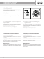
2. INSTALLATION AND TESTING
2. INSTALLATION UND PRÜFUNG
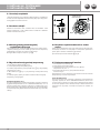
Fig. CFig. B
RED
2070
BLACK DOT
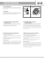
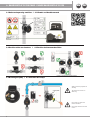
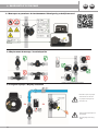
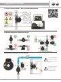
2.3 Limitation of the maximum temperature
1. Remove the red pin (ref.2 fig. B).
2. Set the desired maximum temperature.
3. Locate the printed black dot (ref. 1 Fig. B) between the temperatures
70 and 20 ° C.
4. Insert the pin (ref. 2 Fig. C) into the first slot in front of the black dot.
After successful adjustment, the button cannot be set to any higher
Temperatures than desired one.
Factory setting: 50°C
If necessary, the optional safety temperature switch (item no.
FAW3MAO051085000) can also be installed. This is electrically
connected to the pump and switches it off when the set maximum
temperature is exceeded. For information about the wiring of the safety
temperature monitor, please refer to its operating instructions.
2.1 Installing the unit
The mixing unit is connected directly to the manifold. When installing
the unit in a cabinet, a minimum installation depth of 120 mm must be
taken into account.
2.1 Installing
Die Mischeinheit wird direkt am Heizkreisverteiler angeschlossen.
Bei der Installation der Einheit in einem Verteilerschrank sollte eine
Mindesteinbautiefe von 120 mm berücksichtigt werden.
2.2 Installation of thermostatic head with
capillary sensor
To make it easier to assemble, set the maximum value on the thermo-
static head. Bear in mind you need to set it back to the temperature
envisioned in the project for the floor-mounted system.
Then insert the probe in the well (Ref. 6 Fig. A).
2.2 Einbau des Thermostatkopfes
mit Kappilarfühler
Um die Montage des Thermostatkopfes auf dem Ventil zu erleichtern,
stellen sie bitte die maximale Temperatur am Thermostatkopf ein.
Vergessen Sie nach der Montage aber nicht die Temperatur wie-
der auf die Projekttemperatur einzustellen. Nach der Montage des
Thermostatkopfes schieben Sie den Fernfühler bis zum Anschlag in
die Tauchhülse. Achten Sie bitte darauf, dass Kapillarrohr nicht zu
knicken. (Ref. 6 Fig. A).
2.3 Begrenzung der maximalen Temperatur
1. Entfernen Sie den roten Stift (ref.2 Fig. B).
2. Stellen Sie die gewünschte Maximaltemperatur ein.
3. Suchen Sie den aufgedruckten schwarzen Punkt (ref. 1 Fig. B)
zwischen den Temperaturen 70 und 20 ° C.
4. Setzen Sie den Stift (ref. 2 Fig. C) in den ersten Schlitz vor dem
schwarzen Punkt ein.
Nach erfolgreicher Einstellung kann der Knopf auf keine höheren
Temperaturen als gewünscht eingestellt werden.
Werkseinstellung: 50°C
Wenn notwendig kann auch der optionale Sicherheitstemperaturwächter
(Art.-Nr. FAW3MAO051085000) zusätzlich installiert werden. Dieser
wird elektrisch mit der Pumpe verschaltet und schaltet die bei
Überschreiten der eingestellten Maximaltemperatur ab. Hinweise über
die Verdrahtung des Sicherheitstemperaturwächters entnehmen Sie
bitte dessen Bedienungsanleitung.

5
1. DESCRIZIONE DEI COMPONENTI DEDE
ENEN
2. INSTALLATION AND TESTING
2. INSTALLATION UND PRÜFUNG
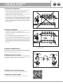
Fig. D
NO
Fig. E
OK
Check valve
Rückschlagventil
Fig. F
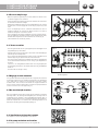
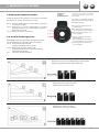
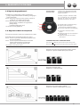
2.4 Testing and filling
– Carry out the hydraulic test on the unit, close the valves and the
lockshields on the manifold.
– At the end of the test, reduce the pressure inside manifolds using
the drain valves.
– Now fill each circuit individually by opening the valve and lockshield
of the single way until all the air comes out.
– For a correct filling connect the water supply to the drain valve in the
flow manifold on the top and a tube to the drainvalve in the return
collector. Inside the mixing unit there is a check valve that prevents
backflow circulation inside the unit, thereby making it easier to expel
the air inside the circuits (fig. D and E).
2.4 Füllen und Spüllen
- Vor dem Füllen die Ventile und die Durchflussmengenmesser am
Verteiler schließen
- Hiernach kann jeder einzelne Kreis nach und nach über die Füll- und
Entleerungshähne gefüllt, entlüftet und gespült werden.
- Bitte beachten Sie das Füllen und Spülen in Flussrichtung
(Wasseranschluss am Vorlauf- Füll- und Entleerungshahn)
durchzuführen (Fig. D und E), da sonst die Durchflussmengenmesser
beschädigt werden könnten. Ferner verhindert das integrierte
Rückschlagventil (Fig. E) der Einheit den hydraulischen Kurzschluss
und ermöglicht das Entlüften der einzelnen Kreise.
2.5 Adjunsting the connection side
It is possible to install the device on the right or left of the manifold
(assembly on the left is the delivery condition). For installation on the
right side of the manifold, it is necessary to turn the head piece by
180°. To do this, please remove the vent valve and the union nut, turn
the head piece by 180° and mount the vent valve and the union nut on
the opposite side (Fig. F).
2.5 Anpassen der Aushlusseit
Es ist möglich, das Gerät rechts oder links an den Heizkreisverteilern
zu installieren (Montage linksseitig ist Lieferzustand). Zu Montage auf
der rechten Verteilerseite ist es notwendig das Kopfstück um 180°
zu drehen. Hierzu entfernen Sie bitte das Entlüftungsventil und die
Überwurfmutter, drehen das Kopfstück um 180° und montieren das
Entlüftungsventil und die Überwurfmutter auf der entgegengesetzten
Seite (Fig. F).
2.6 Venting and setting the pump
See chapter 4, instruction manual at following link
2.6 Entlüften und Einstellen der Pumpe
Siehe Kapitel 4, Bedienungsanleitung unter folgendem Link
DEDE
ENEN

6
DEDE
ENEN
3. BALANCING AND SETTING THE SYSTEM
3. AUSWUCHTEN UND EINSTELLEN DES SYSTEMS
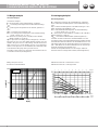
3.1 Design example
Calculation example:
Calculation example:
P = desired power of the radiant heating = 6000 W
tvsek = secondary flow temperature in the radiant heating =
40°C
tvpri = primary flow temperature from the heat generator =
70°C
Δtsek = secondary circuit spread = 5K
tRsek = secondary return temperature of the radiant heating
= tvsek - Δtsek = 40 – 5 = 35°C
V = flow rate secondary circuit =(P [W] x 0.86 / (Δtsek)
= (6000 x 0.86)/ 5 = 1032 l/h
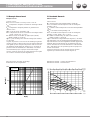
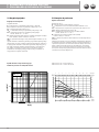
Δpvalv = pressure loss mixing unit (see diagram 1) = 90 mbar.
The pressure loss over the radiant heating circuits must be
added to the pressure loss of the mixing unit. This means that
with a pressure loss in the heating circuits of e.g. 200 mbar,
there is a total pressure loss of 290 mbar (90 + 200 mbar). This
is the head that the pump has to provide and set.
According to the pump curve, the pump must therefore be set
to constant level PC2 (see diagram 2).
Mixing unit pressure lost
Druckverlust Mischereinheit
100
1000
10
Kv=3,5
p [mbar]
Q [l/h]
1000 10000
100
3.1 Auslegungsbeispiel
Berechnungsbeispiel:
P = gewünschte Leistung der Flächenheizung = 6000 W
tvsek = Sekundärvorlauftemperatur in der Flächenheizung =
40°C
tvpri = Primärvorlauftemperatur vom Wärmeerzeuger = 70°C
Δtsek= Spreizung Sekundärkreis = 5K
tRsek = Sekundärrücklauftemperatur der Flächenheizung
= tvsek - Δtsek = 40 – 5 = 35°C
V = Volumenstrom Sekundärkreis =(P [W] x 0,86 / (Δtsek) =
(6000 x 0,86)/ 5 = 1032 l/h
Δpvalv = Druckverlust Mischeinheit (siehe Diagramm 1) =
90 mbar. Zu dem Druckverlust der Mischeinheit muss der
Druckverlust über die Flächenheizungskreise addiert werden.
Das heißt bei einem Druckverlust in den Heizkreisen von z.B.
200 mbar ergibt sich ein Gesamtdruckverlust von 290 mbar
(90 + 200 mbar). Das ist die Förderhöhe, die von der Pumpe
erbracht und eingestellt werden muss.
Gemäß der Pumpenkennlinie muss die Pumpe daher auf
Konstant Stufe PC2 eingestellt werden (siehe Diagramm 2).
00
1
2
3
4
5
6
7
8
10
20
30
40
50
60
70
H
(m)
P
(kPa)
80
0
4
8
12
16
20
24
H
ft
4,50 0,5 1 1,5 2 2,5 3 3,5 4 Q m³h
0 0.2 0.4 0.6 0.8 1.0 Q l/sec
0 10 20 30 40 50 60 Q l/min
1.2
70
0 2 4 6 8 10 12 14 16 Q US gpm
0 2 4 6 8 10 12 14 Q IMP gpm16
18
PP3
PP2
PP1
PC3
PC2
PC1
II
IIII IV VVI
DAB Evosta2 70/130 - Performance Curves
DAB Evosta2 70/130 - Leistung Kurven

7
1. DESCRIZIONE DEI COMPONENTI DEDE
ENEN
3. BALANCING AND SETTING THE SYSTEM
3. AUSWUCHTEN UND EINSTELLEN DES SYSTEMS
3.2 Adjusting the project temperature
The flow temperature (20-50°C) of the underfloor heating
circuit (secondary circuit) is selected on the thermostatic head
(Ref. Fig. A) and held constant (fixed value control). The ther-
mostat head is connected to the remote sensor via a capillary.
Attention:
Normal operation of the underfloor heating may only take
place after the end of the rest and heating time of the screed
(e.g Cement screed 21 days idle time + min. 7 days functional
heating). Before laying the floor coverings, according to EN
1264 functional heating can be carried out. To do this, the
flow temperature must be at 25°C for 3 days and then for at
least 4 days adjusted to the design temperature.
Proceed as follows to preset the design temperature:
1. Set the thermostatic head to the desired flow temperature
value.
2. Wait until the system temperatures have stabilized (second-
ary circuit flow and return temperature should be as constant
as possible) and then compare the secondary circuit spread
with the system calculation.
Commissioning - causes of errors
– Are all heating circuits open and hydraulically balanced?
– Are the actuators open?
– Do the calculated results corresponds to the setting
of the pump curve?
- Are the primary circuit temperature (it should be at least 5K
higher than the desired secondary circuit temperature) and
the primary circuit volume flow sufficient?
3.2 Einstellen der Projekttemperatur
Die Vorlauftemperatur (20-50°C) des Fußbodenheizkreises
(Sekundärkreis) wird am Thermostatkopf gewählt (Ref. Fig. A)
und konstant (Festwertregelung) gehalten. Der Thermostatkopf
ist über eine Kapillare mit dem Fernfühler verbunden.
Achtung:
Der Regelbetrieb der Fußbodenheizung darf erst nach
Beendigung der Ruhe- und Ausheizzeit des Estriches erfol-
gen (z.B. bei Zementestrich 21 Tage Ruhezeit + min. 7 Tage
Funktionsheizen). Vor der Verlegung der Bodenbeläge muss
gemäß EN 1264 das Funktionsheizen durchgeführt werden.
Hierzu muss die Vorlauftemperatur für 3 Tage auf 25°C und
danach für min. 4 Tage auf Auslegungstemperatur eingestellt
werden.
Für die Voreinstellung der Auslegungstemperatur wird wie folgt
vorgegangen:
1. Den Thermostatkopf auf den gewünschten Wert der
Vorlauftemperatur einstellen.
2. Abwarten bis sich die Systemtemperaturen stabili-
siert haben (möglichst konstante Sekundärkreis Vor- und
Rücklauftemperatur) und danach die Sekundärkreisspreizung
mit der Berechnung der Anlage vergleichen.
Inbetriebnahme - Fehlerursachen
- Sind alles Heizkreise geöffnet und hydraulisch abgeglichen?
- Sind die Stellantriebe geöffnet?
- Entspricht die Einstellung der Pumpenkurve den errechneten
Ergebnissen
- Ist die Primärkreistemperatur (sie sollte min. 5K höher,als
die gewünschte Sekundärtkreistemperatur liegen) und der
Primärkreisvolumenstrom ausreichend?

8
DEDE
ENEN
4. DAB EVOSTA 2 70/130 PUMP - PUMPE DAB EVOSTA 2 70/130
ITALIANO
3
Morsetti di rete e i morsetti motore possono portare tensione pericolosa anche a
motore fermo.
Se il cavo di alimentazione è danneggiato, esso deve essere sostituito dal servizio
assistenza tecnica o da personale qualificato, in modo da prevenire ogni rischio.
3. DESCRIZIONE DEL PRODOTTO
Figura 1: Liquidi pompati, avvisi e condizioni di funzionamento
I circolatori della serie EVOSTA2 OEM costituiscono una gamma completa di circolatori.
Le presenti istruzioni di installazione e funzionamento descrivono i modelli EVOSTA2 OEM.
Il tipo di modello è indicato sulla confezione e sulla targhetta di identificazione.
La tabella di seguito mostra i modelli EVOSTA2 OEM con funzioni e funzionalità integrate.
Funzioni/Funzionalità EVOSTA2 OEM
Pressione Proporzionale ●
Pressione Costante ●
Curva costante
Protezione contro la marcia a secco
Degasazione Automatica
Tabella 1: Funzioni e funzionalità
4. LIQUIDI POMPATI
Pulito, libero da sostanze solide e oli minerali, non viscoso, chimicamente neutro, prossimo alle caratteristiche
dell’acqua (glicole max. 30%).
5. APPLICAZIONI
I circolatori della serie EVOSTA2 OEM consentono una regolazione integrata della pressione differenziale che
permette di adattare le prestazioni del circolatore alle effettive richieste dell’impianto. Questo determina
notevoli risparmi energetici, una maggiore controllabilità dell’impianto e una riduzione della rumorosità.
I circolatori EVOSTA2 OEM sono concepiti per la circolazione di:
– acqua in impianti di riscaldamento e condizionamento.
– acqua in circuiti idraulici industriali.
I circolatori EVOSTA2 OEM sono autoprotetti contro:
– Sovraccarichi
– Mancanza di fase
ITALIANO
6
8.2 Posizioni Interfaccia Utente
Montare il circolatore EVOSTA2 OEM sempre con l’albero motore in posizione
orizzontale.
Montare il dispositivo di controllo elettronico in posizione verticale.
Figura 3: Posizione di montaggio
Il circolatore può essere installato negli impianti di riscaldamento e condizionamento sia sulla tubazione di
mandata che su quella di ritorno; la freccia stampata sul corpo pompa indica la direzione del flusso.
Installare per quanto possibile il circolatore sopra il livello minimo della caldaia, ed il più lontano possibile
da curve, gomiti e derivazioni.
Per facilitare le operazioni di controllo e manutenzione, installare sia sul condotto di aspirazione che su
quello di mandata una valvola di intercettazione.
Prima di installare il circolatore, effettuare un accurato lavaggio dell’impianto con sola acqua ad 80°C.
Quindi scaricare completamente l’impianto per eliminare ogni eventuale sostanza dannosa che fosse
entrata in circolazione.
Evitare di mescolare all’acqua in circolazione additivi derivanti da idrocarburi e prodotti aromatici.
L’aggiunta di antigelo, dove necessario, si consiglia nella misura massima del 30%.
In caso di coibentazione (isolamento termico) utilizzare l’apposito kit (se fornito in dotazione) ed accertarsi
che i fori di scarico condensa della cassa motore non vengano chiusi o parzialmente ostruiti.
Nel caso di manutenzione utilizzare sempre un set di guarnizioni nuove.
Non coibentare mai il dispositivo di controllo elettronico.
ITALIANO
7
8.2 1 Posizionamento dell’ interfaccia utente negli impianti di riscaldamento
È possibile posizionare l’interfaccia utente con il cavo rivolto a sinistra, destra e verso l’alto.
Figura 4: Posizioni dell’interfaccia utente
8.3 Rotazione dell’interfaccia utente
Nel caso l’installazione venga effettuata su tubazioni poste in orizzontale sarà necessario effettuare una
rotazione di 90 gradi dell’interfaccia con relativo dispositivo elettronico al fine di mantenere il grado di
protezione IP e per permettere all’utente un’interazione con l’interfaccia grafica più confortevole.
Prima di procedere alla rotazione del circolatore, assicurarsi che il circolatore stesso
sia stato completamente svuotato.
Per ruotare il circolatore EVOSTA2 OEM procedere come segue:
1. Rimuovere le 4 viti di fissaggio della testa del circolatore.
2. Ruotare di 90 gradi la cassa motore insieme al dispositivo di controllo elettronico in senso orario o
antiorario a seconda della necessità.
3. Rimontare ed avvitare le 4 viti che fissano la testa del circolatore.
Il dispositivo di controllo elettronico deve rimanere sempre in posizione verticale!
Figura 5: Cambiamento della posizione dell’interfaccia utente
ITALIANO
10
10.1 Degasazione della pompa
Figura 7: Sfiato della pompa
Sfiatare sempre la pompa prima dell’avviamento!
La pompa non deve funzionare a secco.
11. FUNZIONI
11.1 Modi di Regolazione
I circolatori EVOSTA2 OEM consentono di effettuare le seguenti modalità di regolazione a seconda delle
necessità dell’impianto:
− Regolazione a pressione differenziale proporzionale in funzione del flusso presente nell’impianto.
− Regolazione a pressione differenziale costante.
− Regolazione a curva constante (giri fissi).
La modalità di regolazione può essere impostata attraverso il pannello di controllo EVOSTA2 OEM.
4.2 Position of the user interface / 4.2 Position der Benutzeroberfläche
4.1 Notice and operating condition / 4.1 Hinweis und Betriebszustand
4.3 Bleeding the pump / 4.3 Entlüften der Pumpe
Always vent the pump before
starting!
The pump must never run
when dry.
Die Pumpe vor dem Start
immer entlüften!
Die Pumpe darf nicht trocken
laufen.

9
DEDE
ENEN
4. DAB EVOSTA 2 70/130 PUMP - DAB EVOSTA 2 70/130 PUMPE
4.4 Adjusting the control curves
Depending on the system requirements, EVOSTA2 circu-
lating pumps enable the following control modes:
PP1-3: Proportional differential pressure
control depending on the flow rate
CP1-3: Control at constant differential pressure
(preferred setting for panel heating;
factory setting CP3)
I-VI: Constant speed control
4.4 Einstellung der Regelkurven
EVOSTA2 Umwälzpumpe ermöglichen je nach
Anlagenanforderung folgende Regelmodi:
PP1-3: Proportionale Differenzdruckregelung in
Abhängigkeit der Fördermenge
CP1-3: Regelung bei konstantem Differenzdruck
(bevorzugte Einstellung bei Flächenheizungen;
Werkseinstellung CP3)
I-VI: Regelung mit konstanter Drehzahl
Regulation with Proportional Differential Pressure
Regelung mit proportionalem Differenzdruck
Regulation with constant speed
Regelung mit konstanter Drehzahl
ITALIANO
12
12. PANNELLO DI CONTROLLO
Le funzionalità dei circolatori EVOSTA2 OEM possono essere modificate tramite il pannello di controllo posto
sul coperchio del dispositivo di controllo elettronico.
12.1 Elementi sul Display
Figura 8: Display
1 Tasto per la selezione dell’impostazione della pompa
2 Segmenti luminosi che indicano il tipo di curva impostata
3 Segmenti luminosi che indicano la curva impostata
1
2
3
Control panel
Schalttafel
The functions of EVOSTA2 circulators can
be modified via the control panel.
Die Funktionen der EVOSTA2
Umwälzpumpen können über das
Bedienfeld geändert werden.
1 Key for selecting the pump setting
2 LED segments indicating the intensity of set curve
3 LED icons indicating the kind of curve
1 Taste zur Auswahl der Pumpeneinstellung
2 LED Segmernte zeigen die Intensität der eingestellten
Kurve an
3 LED Symbole zeigen die Art der eingestellten Kurve an
Regulation with constant curve
Regelung mit konstanter Kurve

10
1. DESCRIZIONE DEI COMPONENTI NLNL
FRFR
INDEX
1. DESCRIPTION ......................................... 11
1.1 Construction
1.2 Données techniques
2. INSTALLATION ET ESSAI ........................12
2.1 Installation de l’unité
2.2 Installation d’une tête thermostatique avec capteur capillaire
2.3 Limitation de la température maximale
2.4 Essais et remplissage
2.5 Réglage du côté connexion
2.6 Ventilation et réglage de la pompe
3. EQUILIBRAGE ET RÉGLER DU
SYSTÈME ....................................................... 14
3.1 Exemple dimensionnel
3.2 Réglage de la température du projet
4. DAB EVOSTA 2 70/130 PUMP ................16
4.1 Remarques et paramètres de fonctionnement
4.2 Emplacement de montage
4.3 Purge de la pompe
4.4 Réglage des courbes de contrôle
1. BESCHREIBUNG ...................................... 11
1.1 Bouw
1.2 Technische gegevens
2. INSTALLATIE EN TESTEN ....................... 12
2.1 Het apparaat installeren
2.2 Installatie van thermostatische kop met capillaire sensor
2.3 Beperking van de maximumtemperatuur
2.4 Testen en vullen
2.5 De aansluitzijde afstellen
2.6 De pomp ontluchten en instellen
3. BALANCEREN EN INSTELLEN
VAN HET SYSTEEM ................................14
3.1 Voorbeeld dimensie
3.2 Reglement van de temperatuur van het project
4. DAB EVOSTA 2 70/130 PUMP ....................16
4.1 Opmerkingen en bedrijfsparameters
4.2 Installatiepositie
4.3 De pomp ontluchten
4.4 Instellen van de regelcurven
NLNL
Hartelijk dank dat u ons vertrouwt en een van onze producten
hebt gekocht. We vragen u deze handleiding zorgvuldig door
te lezen, die alle specificaties en alle relevante informa-
tie bevat voor een correcte werking. De informatie in deze
handleiding kan indien nodig worden aangepast als gevolg
van technische wijzigingen.
® Alle rechten voorbehouden. Niets uit deze publicatie mag
worden gereproduceerd of verspreid zonder de schriftelijke
toestemming van Purmo Group.
FRFR
Nous vous remercions de nous avoir fait confiance et d'avoir
acheté l'un de nos produits. Nous vous demandons de lire
attentivement ce manuel, qui contient toutes les spécifica-
tions et toutes les informations pertinentes pour un fonction-
nement correct. Les informations contenues dans ce manuel
peuvent être adaptées si nécessaire en raison de modifica-
tions techniques.
® Tous droits réservés. Aucune partie de cette publication ne
peut être reproduite ou distribuée sans l'autorisation écrite
du Groupe Purmo.

11
NLNL
FRFR
h
i
210
49
190
130
50
305
23
94
1. DESCRIPTION
/
BESCHREIBUNG
1.1 Construction
Nb. 1 Vanne mélangeuse avec filetage de raccordement
M30x1,5 pour la fixation d'une tête thermostatique 20-65°C
avec capteur capillaire ou d'un servomoteur électrique (non
inclus) ;
Nb. 1 Tête thermostatique 20-65°C avec capteur capillaire ;
Nb. 1 clapet anti-retour ;
Nb. 1 Vanne d'aération
Nb. 1 thermomètre 0-80°C ;
Nb. 1 doigt de gant pour capteur capillaire
Nb. 1 jeu de vannes à bille (non inclus);
h
Nr. 1 Pompe à haut rendement DAB EVOSTA 2 70/130 (1")
(selon version)
i
Nr. 1 Jeu de connecteurs Filetage mâle 1" x écrou-raccord 1"
1.2 Données techniques
Primary circuit ma Température maximale
du circuit primaire: aximum temperature: 90 °C
Pression maximale: 10 bar
ΔP max circuit primaire: 1 bar
Plage de réglage secondaire:
(réglage de la température fixe de départ)
20÷65 °C
Unité de mélange Pertes de charge Kv 3,5
Thermometer scale: 0÷80 °C
Connexions côté primaire G 1” F
Connexions côté secondaire G 1” M
Connexions du circulateur :
G 1” - takeoffs 130 mm
1.1 Bouw
Nr. 1 Mengkraan met M30x1,5 aansluitschroefdraad voor het
bevestigen van een thermostaatkop 20-65°C met capillaire
sensor of een elektrische servomotor (niet meegeleverd);
Nr. 1 Thermostaatkop 20-65°C met capillaire sensor;
Nr. 1 Terugslagklep;
Nr. 1 ontluchtingsventiel
Nr. 1 thermometer 0-80°C;
Nr. 1 dompelhuls voor capillaire sensor
Nr. 1 set kogelkranen (niet inbegrepen);
h
Nr. 1 Hoogrendementspomp DAB EVOSTA 2 70/130 (1")
(afhankelijk van de versie)
i
Nr. 1 Set connectoren 1" buitendraad x 1" wartelmoer
1.2 Technische gegevens
Primair circuit ma Maximale temperatuur
van het primaire circuit: aximum temper-
atuur:
90 °C
Maximale druk: 10 bar
ΔP max primair circuit: 1 bar
Secundair controlebereik:
(vaste aanvoertemperatuurinstelling) 20÷65 °C
Mengeenheid Drukval Kv 3,5
Thermometerschaal: 0÷80 °C
Aansluitingen aan de primaire zijde G 1” F
Aansluitingen aan de secundaire zijde G 1” M
Aansluitingen van de circulatietoren: G 1” - takeoffs 130 mm
Fig. A
Boiler Flow Boiler return

12
NLNL
FRFR
2. INSTALLATION ET ESSAIS
2. INSTALLATIE EN TESTEN
Fig. CFig. B
RED
2070
BLACK DOT
2.3 Limitation de la température maximale
1. Retirez la goupille rouge (réf. fig. B).
2. Régler la température maximale souhaitée.
3. Localisez le point noir imprimé (réf. fig. B) entre les températures
70 et 20 ° C.
4. Insérez la goupille (réf. Fig. C) dans la première fente située devant
le point noir.
Après un réglage réussi, le bouton ne peut pas être réglé sur une valeur
supérieure. Des températures plus élevées que désirées.
Réglage en usine: 50 °C
Si nécessaire, l’interrupteur de température de sécurité en option (réf.
FAW3MAO051085000) peut également être installé. Il est raccordé
électriquement à la pompe et l’éteint lorsque la température maximale
2.1 Installation de l'unité
L'unité de mélange est connectée directement au collecteur. Lors de
l'installation de l'unité dans une armoire, il faut tenir compte d'une
profondeur d'installation minimale de 120 mm.
2.1 Installatie
De mengeenheid wordt rechtstreeks op de verdeler aangesloten. Bij
montage van de eenheid in een kast moet rekening worden gehouden
met een minimale inbouwdiepte van 120 mm.
2.2 Installation d’une tête thermostatique avec
capteur capillair
e
Pour faciliter le montage, réglez la valeur maximale sur la tête thermo-
statique. N'oubliez pas que vous devez la régler sur la température
prévue dans le projet pour le système au sol.
Insérez ensuite la sonde dans le puits (Réf. Fig. A).
2.2 Installatie van thermostatische kop met
capillaire sensor
Om de montage te vergemakkelijken, moet u de maximumwaarde op
de thermostaatkop instellen. Houd er rekening mee dat u deze moet
terugstellen op de temperatuur die in het project voor het vloermon-
tagesysteem is voorzien.
Plaats vervolgens de sonde in de put (ref. Fig. A).
2.3 Beperking van de maximumtemperatuur
1. Verwijder de rode pen (ref.2 fig. B).
2. Stel de gewenste maximum temperatuur in.
3. Zoek de gedrukte zwarte stip (ref. 1 afb. B) tussen de temperaturen
70 en 20 ° C.
4. 4. Steek de pen (ref. 2 Fig. C) in de eerste gleuf voor de zwarte stip.
Na een succesvolle aanpassing kan de knop niet op een hogere waarde
worden ingesteld. Temperaturen dan gewenst.
Fabrieksinstelling: 50 °C.
Indien nodig kan ook de optionele veiligheidstemperatuurschakelaar
(FAW3MAO051085000) worden geïnstalleerd. Hij is elektrisch aange-
sloten op de pomp en wordt uitgeschakeld wanneer de maximumtem-
peratuur is bereikt

13
1. DESCRIZIONE DEI COMPONENTI NLNL
FRFR
2. INSTALLATION ET ESSAIS
2. INSTALLATIE EN TESTEN
Fig. D
NO
Fig. E
OK
Check valve
Rückschlagventil
Fig. F
2.4 Essai et remplissage
- Effectuer l'épreuve hydraulique sur l'unité, fermer les vannes et les
coudes de réglage sur le collecteur.
- A la fin de l'épreuve, réduisez la pression à l'intérieur des collecteurs
en utilisant les vannes de vidange.
- Remplissez maintenant chaque circuit individuellement en ouvrant
la vanne et le coude de réglage de la voie unique jusqu'à ce que l'air
sorte.
- Pour un remplissage correct, connectez l'alimentation en eau au
robinet de vidange du collecteur de départ en haut et un tube au
robinet de vidange du collecteur de retour.
retour. A l'intérieur du groupe de mélange se trouve un clapet anti-re-
tour qui empêche la circulation à contre-courant à l'intérieur de l'unité,
facilitant ainsi l'expulsion de l'air à l'intérieur des circuits (fig. 2).
l'air à l'intérieur des circuits (fig. D et E).
2.4 Testen en vullen
- Voer de hydraulische test uit op het apparaat, sluit de kleppen en de
vergrendelingen op de verdeler.
- Aan het einde van de test verlaagt u de druk in de verdeelleidingen
met behulp van de aftapkranen.
- Vul nu elk circuit afzonderlijk door de klep en het sluitschild van de
enkelvoudige weg te openen totdat alle lucht eruit komt.
- Voor een correcte vulling sluit u de watertoevoer aan op de aftapkraan
in de aanvoerverdeler bovenaan en een slang op de aftapkraan in
de retour
collector. In de mengeenheid bevindt zich een terugslagklep die
terugstroming voorkomt in de eenheid, waardoor het gemakkelijker
wordt om
de lucht in de circuits (fig. D en E).
2.5 Réglage du côté connexion
Il est possible d'installer le dispositif à droite ou à gauche du collecteur
(le montage à gauche est la condition de livraison). Pour l'installation
sur le côté droit du collecteur, il est nécessaire de tourner la pièce
de tête de 180°. Pour ce faire, il faut enlever la soupape d'aération et
l'écrou-raccord, tourner la tête de 180° et monter la soupape d'aération
et l'écrou-raccord sur le côté opposé (Fig. F).
2.5 De aansluitzijde afstellen
Het is mogelijk het toestel rechts of links van de verdeler te monteren
(montage links is de leveringsomstandigheid). Voor montage aan de
rechterkant van de verdeler is het noodzakelijk het kopstuk 180° te
draaien. Verwijder hiervoor het ontluchtingsventiel en de wartelmoer,
draai het kopstuk 180° en monteer het ontluchtingsventiel en de
wartelmoer aan de tegenovergestelde zijde (Fig. F).
2.6 Ventilation et réglage de la pompe
Voir chapitre 4, manuel d'instruction au lien suivant
2.6 De pomp ontluchten en instellen
Zie hoofdstuk 4, manuel d'instruction, op de volgende link

14
NLNL
FRFR
3. ÉQUILIBRER ET RÉGLER LE SYSTÈME
3. BALANCEREN EN INSTELLEN VAN HET SYSTEEM
3.1 Exemple dimensionnel
Exemple de calcul
Données du projet :
P = puissance souhaitée du chauffage radiant = 6000 W
tvsek =température de départ secondaire du chauffage radiant
= 40°C
tvpri = température de départ primaire du générateur de
chaleur = 70°C
Δtsek = écart du circuit secondaire = 5K
tRsek = température de retour secondaire du chauffage radiant
= tvsek - Δtsek = 40 - 5 = 35°C
V = débit du circuit secondaire =(P [W] x 0,86 / (Δtsek)
= (6000 x 0,86)/ 5 = 1032 l/h
Δpvalv = perte de charge de l'unité de mélange (voir schéma
1) = 90 mbar.
La perte de pression sur les circuits de chauffage rayonnant
doit être ajoutée à la perte de pression de l'unité de mélange.
Cela signifie qu'avec une perte de pression dans les circuits
de chauffage de 200 mbar par exemple, il y a une perte de
pression totale de 290 mbar (90 + 200 mbar). C'est la hau-
teur manométrique que la pompe doit fournir et régler.
Selon la courbe de la pompe, la pompe doit donc être réglée
sur le niveau constant PC2 (voir diagramme 2).
3.1 Voorbeeld dimensie
Rekenvoorbeeld:
Rekenvoorbeeld
P = desired power of the radiant heating = 6000 W
tvsek = secundaire aanvoertemperatuur in de stralingsver-
warming = 40°C
tvpri = primaire aanvoertemperatuur van de warmteopwekker
= 70°C
Δtsek = secundaire circuitspreiding = 5K
tRsek = secundaire retourtemperatuur van de stralingsver-
warming = tvsek - Δtsek = 40 - 5 = 35°C
V = debiet secundaire kring =(P [W] x 0,86 / (Δtsek)
= (6000 x 0,86)/ 5 = 1032 l/h
Δpvalv = drukverlies mengeenheid (zie diagram 1) = 90 mbar.
Het drukverlies over de stralingsverwarmingskringen moet
bij het drukverlies van de mengeenheid worden opgeteld. Dit
betekent dat bij een drukverlies in de verwarmingscircuits
van b.v. 200 mbar er een totaal drukverlies is van 290 mbar
(90 + 200 mbar). Dit is de opvoerhoogte die de pomp moet
leveren en instellen.
Volgens de pompcurve moet de pomp daarom worden
ingesteld op constant niveau PC2 (zie diagram 2).
Perte de pression de l'unité de mélange
Drukverlies van de mengeenheid
100
1000
10
Kv=3,5
p [mbar]
Q [l/h]
1000 10000
100
00
1
2
3
4
5
6
7
8
10
20
30
40
50
60
70
H
(m)
P
(kPa)
80
0
4
8
12
16
20
24
H
ft
4,50 0,5 1 1,5 2 2,5 3 3,5 4 Q m³h
0 0.2 0.4 0.6 0.8 1.0 Q l/sec
0 10 20 30 40 50 60 Q l/min
1.2
70
0 2 4 6 8 10 12 14 16 Q US gpm
0 2 4 6 8 10 12 14 Q IMP gpm16
18
PP3
PP2
PP1
PC3
PC2
PC1
II
IIII IV VVI
DAB Evosta2 70/130 - Courbes de performances
DAB Evosta2 70/130 - Prestatiecurves

15
1. DESCRIZIONE DEI COMPONENTI NLNL
FRFR
3. ÉQUILIBRER ET RÉGLER LE SYSTÈME
3. BALANCEREN EN INSTELLEN VAN HET SYSTEEM
3.3 Reglement van de temperatuur van het project
Thermostatische regeling met thermostaatkop
De aanvoerwatertemperatuur van het vloersysteem wordt ingesteld
De aanvoertemperatuur (20-50 °C) van het vloerverwarmingscircuit
(secundair circuit) wordt geselecteerd op de thermostaatkop (Zie Afb.
A) en constant gehouden (vaste waarderegeling). De thermostaatkop
is via een capillair verbonden met de afstandssensor.
Aandacht:
Normaal bedrijf van de vloerverwarming mag pas plaatsvin-
den na het einde van de rust- en opwarmtijd van de dekvloer
(bijv. Cementdekvloer 21 dagen leegloop + min. 7 dagen
functionele verwarming). Voordat de vloerbedekking wordt
gelegd, kan volgens EN 1264 functionele verwarming worden
uitgevoerd. Hiervoor dient de aanvoertemperatuur 3 dagen
op 25°C te zijn en daarna minimaal 4 dagen aangepast te
worden aan de ontwerptemperatuur.
Ga als volgt te werk om de ontwerptemperatuur vooraf in te stellen:
1. Stel de thermostaatkop in op de gewenste aanvoertemperatuur-
waarde.
2. Wacht tot de systeemtemperaturen gestabiliseerd zijn (aanvoer- en
retourtemperatuur secundair circuit moeten zo constant mogelijk zijn)
en vergelijk vervolgens de spreiding van het secundaire circuit met
de systeemberekening.
Inbedrijfstelling - oorzaken van fouten
- Zijn alle verwarmingscircuits open en hydraulisch gebalanceerd?
- Staan de aandrijvingen open?
- Komt overeen met de instelling van de pompcurve de berekende
resultaten
- Zijn de primaire circuittemperatuur (deze moet minimaal 5K hoger
zijn dan de gewenste secundaire circuittemperatuur) en de primaire
circuitvolumestroom voldoende?
3.2 Réglage de la température du projet
Régulation thermostatique avec la tête thermostatique
La température de départ (20-50°C) du circuit de chauffage par le sol
(circuit secondaire) est sélectionnée sur la tête thermostatique (Réf.
Fig. A) et maintenue constante (régulation à valeur fixe). La tête du
thermostat est connectée au capteur à distance via un capillaire.
Attention:
Le fonctionnement normal du chauffage au sol ne peut avoir
lieu qu'après la fin du temps de repos et de chauffage de la
chape (par exemple, chape de ciment 21 jours d'inactivité +
min. 7 jours de chauffage fonctionnel). Avant de poser les
revêtements de sol, selon la norme EN 1264, un chauffage
fonctionnel peut être effectué. Pour ce faire, la température
de départ doit être à 25°C pendant 3 jours puis pendant au
moins 4 jours ajustée à la température de conception.
Procédez comme suit pour prérégler la température de conception :
1. Réglez la tête thermostatique sur la valeur de température de départ
souhaitée.
2. Attendez que les températures du système se soient stabilisées (les
températures de départ et de retour du circuit secondaire doivent être
aussi constantes que possible), puis comparez l'étalement du circuit
secondaire avec le calcul du système.
Mise en service - causes d'erreurs
- Tous les circuits de chauffage sont-ils ouverts et hydrauliquement
équilibrés ?
- Les actionneurs sont-ils ouverts ?
- Correspond au réglage de la courbe de la pompe les résultats calculés
- La température du circuit primaire (elle doit être supérieure d'au
moins 5K à la température souhaitée du circuit secondaire) et le débit
volumique du circuit primaire sont-ils suffisants ?

16
NLNL
FRFR
4. DAB EVOSTA 2 70/130 PUMP
ITALIANO
3
Morsetti di rete e i morsetti motore possono portare tensione pericolosa anche a
motore fermo.
Se il cavo di alimentazione è danneggiato, esso deve essere sostituito dal servizio
assistenza tecnica o da personale qualificato, in modo da prevenire ogni rischio.
3. DESCRIZIONE DEL PRODOTTO
Figura 1: Liquidi pompati, avvisi e condizioni di funzionamento
I circolatori della serie EVOSTA2 OEM costituiscono una gamma completa di circolatori.
Le presenti istruzioni di installazione e funzionamento descrivono i modelli EVOSTA2 OEM.
Il tipo di modello è indicato sulla confezione e sulla targhetta di identificazione.
La tabella di seguito mostra i modelli EVOSTA2 OEM con funzioni e funzionalità integrate.
Funzioni/Funzionalità EVOSTA2 OEM
Pressione Proporzionale ●
Pressione Costante ●
Curva costante
Protezione contro la marcia a secco
Degasazione Automatica
Tabella 1: Funzioni e funzionalità
4. LIQUIDI POMPATI
Pulito, libero da sostanze solide e oli minerali, non viscoso, chimicamente neutro, prossimo alle caratteristiche
dell’acqua (glicole max. 30%).
5. APPLICAZIONI
I circolatori della serie EVOSTA2 OEM consentono una regolazione integrata della pressione differenziale che
permette di adattare le prestazioni del circolatore alle effettive richieste dell’impianto. Questo determina
notevoli risparmi energetici, una maggiore controllabilità dell’impianto e una riduzione della rumorosità.
I circolatori EVOSTA2 OEM sono concepiti per la circolazione di:
– acqua in impianti di riscaldamento e condizionamento.
– acqua in circuiti idraulici industriali.
I circolatori EVOSTA2 OEM sono autoprotetti contro:
– Sovraccarichi
– Mancanza di fase
ITALIANO
6
8.2 Posizioni Interfaccia Utente
Montare il circolatore EVOSTA2 OEM sempre con l’albero motore in posizione
orizzontale.
Montare il dispositivo di controllo elettronico in posizione verticale.
Figura 3: Posizione di montaggio
Il circolatore può essere installato negli impianti di riscaldamento e condizionamento sia sulla tubazione di
mandata che su quella di ritorno; la freccia stampata sul corpo pompa indica la direzione del flusso.
Installare per quanto possibile il circolatore sopra il livello minimo della caldaia, ed il più lontano possibile
da curve, gomiti e derivazioni.
Per facilitare le operazioni di controllo e manutenzione, installare sia sul condotto di aspirazione che su
quello di mandata una valvola di intercettazione.
Prima di installare il circolatore, effettuare un accurato lavaggio dell’impianto con sola acqua ad 80°C.
Quindi scaricare completamente l’impianto per eliminare ogni eventuale sostanza dannosa che fosse
entrata in circolazione.
Evitare di mescolare all’acqua in circolazione additivi derivanti da idrocarburi e prodotti aromatici.
L’aggiunta di antigelo, dove necessario, si consiglia nella misura massima del 30%.
In caso di coibentazione (isolamento termico) utilizzare l’apposito kit (se fornito in dotazione) ed accertarsi
che i fori di scarico condensa della cassa motore non vengano chiusi o parzialmente ostruiti.
Nel caso di manutenzione utilizzare sempre un set di guarnizioni nuove.
Non coibentare mai il dispositivo di controllo elettronico.
ITALIANO
7
8.2 1 Posizionamento dell’ interfaccia utente negli impianti di riscaldamento
È possibile posizionare l’interfaccia utente con il cavo rivolto a sinistra, destra e verso l’alto.
Figura 4: Posizioni dell’interfaccia utente
8.3 Rotazione dell’interfaccia utente
Nel caso l’installazione venga effettuata su tubazioni poste in orizzontale sarà necessario effettuare una
rotazione di 90 gradi dell’interfaccia con relativo dispositivo elettronico al fine di mantenere il grado di
protezione IP e per permettere all’utente un’interazione con l’interfaccia grafica più confortevole.
Prima di procedere alla rotazione del circolatore, assicurarsi che il circolatore stesso
sia stato completamente svuotato.
Per ruotare il circolatore EVOSTA2 OEM procedere come segue:
1. Rimuovere le 4 viti di fissaggio della testa del circolatore.
2. Ruotare di 90 gradi la cassa motore insieme al dispositivo di controllo elettronico in senso orario o
antiorario a seconda della necessità.
3. Rimontare ed avvitare le 4 viti che fissano la testa del circolatore.
Il dispositivo di controllo elettronico deve rimanere sempre in posizione verticale!
Figura 5: Cambiamento della posizione dell’interfaccia utente
ITALIANO
10
10.1 Degasazione della pompa
Figura 7: Sfiato della pompa
Sfiatare sempre la pompa prima dell’avviamento!
La pompa non deve funzionare a secco.
11. FUNZIONI
11.1 Modi di Regolazione
I circolatori EVOSTA2 OEM consentono di effettuare le seguenti modalità di regolazione a seconda delle
necessità dell’impianto:
− Regolazione a pressione differenziale proporzionale in funzione del flusso presente nell’impianto.
− Regolazione a pressione differenziale costante.
− Regolazione a curva constante (giri fissi).
La modalità di regolazione può essere impostata attraverso il pannello di controllo EVOSTA2 OEM.
4.2 Emplacement de montage / Installatiepositie
4.1 Remarques et paramètres de fonctionnement / Kennisgeving en bedrijfstoestand
4.3 Purge de la pompe / De pomp ontluchten
Évacuez toujours la pompe
avant la mise en service!
La pompe ne doit pas fon-
ctionner à sec.
Ontlucht de pomp altijd voor
het starten!
De pomp mag nooit droog
lopen.

17
NLNL
FRFR
4. DAB EVOSTA 2 70/130 PUMP
4.4
Réglage des courbes de contrôle
Selon les exigences du système, les circulateurs EVOSTA2
permettent les modes de régulation suivants :
PP1-3: Pression différentielle proportionnelle régulation
en fonction du débit
CP1-3: Régulation à pression différentielle constante
(réglage préféré pour le chauffage par panneau ;
réglage d'usine CP3)
I-VI : Contrôle de la vitesse constante
4.4
Instellen van de regelcurven
Afhankelijk van de systeemvereisten maken EVOSTA2-
circulatiepompen de volgende regelmodi mogelijk:
PP1-3: Proportionele verschildruk
regeling afhankelijk van het debiet
CP1-3: Regeling bij constant drukverschil
(voorkeursinstelling voor paneelverwarming;
fabrieksinstelling CP3)
I-VI: Constante snelheidsregeling
Régulation avec pression différentielle proportionnelle
Regeling met proportionele differentiële druk
Régulation à vitesse constante
Regeling met constante snelheid
ITALIANO
12
12. PANNELLO DI CONTROLLO
Le funzionalità dei circolatori EVOSTA2 OEM possono essere modificate tramite il pannello di controllo posto
sul coperchio del dispositivo di controllo elettronico.
12.1 Elementi sul Display
Figura 8: Display
1 Tasto per la selezione dell’impostazione della pompa
2 Segmenti luminosi che indicano il tipo di curva impostata
3 Segmenti luminosi che indicano la curva impostata
1
2
3
Panneau de
contrôle
Bedieningspaneel
Les fonctions des circulateurs EVOSTA2
peuvent être modifiées via le panneau
de commande.
De functies van EVOSTA2 circulatie-
pompen kunnen worden gewijzigd via
het bedieningspaneel.
1 Toets voor het selecteren van de
pompinstelling
2 LED-segmenten die de intensiteit
van de ingestelde curve aangeven
3 LED-pictogrammen die het soort
curve aangeven
1 Toets voor het selecteren van de
pompinstelling
2 LED-segmenten die de intensiteit
van de ingestelde curve aangeven
3 LED-pictogrammen die het soort
curve aangeven
Régulation avec courbe constante
Regeling met constante curve

18
INDEX
PLPL
Dziękujemy za zaufanie i zakup jednego z naszych produktów. Prosimy
o dokładne przeczytanie niniejszej instrukcji, która zawiera wszystkie
dane techniczne i wszystkie istotne informacje dotyczące prawidłowej
obsługi. Informacje zawarte w niniejszej instrukcji mogą być w razie
potrzeby dostosowywane ze względu na zmiany techniczne.
®
wszelkie prawa zastrzeżone. Żadna część niniejszej publikacji
nie może być powielana ani rozpowszechniana bez pisemnej zgody
grupy Purmo.
RORO
Vă mulțumim pentru încrederea în noi și pentru achiziționarea unuia
dintre produsele noastre.
Vă rugăm să citiți cu atenție acest manual, care conține toate
specificațiile și toate informațiile relevante pentru operarea corectă.
Informațiile conținute în acest manual pot fi ajustate dacă este nece-
sar, datorită modificărilor tehnice survenite.
®
Toate drepturile sunt rezervate. Nici o parte a publicației nu poate
fi reprodusă sau distribuită fără permisiunea scrisă a Purmo Group.
1. DESCRIERE .............................................. 18
1.1 Componente
1.2 Date tehnice
2. INSTALARE ȘI TESTARE ........................20
2.1 Instalarea unității
2.2 Instalarea capului termostatic cu senzor capilar
2.3 Limitarea temperaturii maxime
2.4 Testare și umplere
2.5 Reglarea părții de conectare
2.6 Aerisirea și reglarea pompei
3. ECHILIBRAREA ȘI REGLAREA
SISTEMULUI ..........................................22
3.1 Exemplu de proiectare
3.2 Reglarea temperaturii proiectului
4. DAB EVOSTA 2 70/130 PUMP ...............24
4.1 Note și parametri de funcționare
4.2 Poziția de instalare
4.3 Aerisirea pompei
4.4 Reglarea curbelor de funcționare
1. OPIS ........................................................ 18
1.1 Budowa
1.2 Dane techniczne
2. INSTALACJA I TESTOWANIE ...............20
2.1 Instalacja urządzenia
2.2 Montaż głowicy termostatycznej z czujnikiem kapilarnym
2.3 Ograniczenie maksymalnej temperatury
2.4 Testowanie i napełnianie
2.5 Zmiana strony połączenia
2.6 Odpuszczanie i ustawianie pompy
3.
RÓWNOWAŻENIE I USTAWIANIE
................ 22
3.1 Przykład projektu
3.2 Regulacja temperatury roboczej
4. POMPA DAB EVOSTA 2 70/130 8 ................24
4.1 Uwagi i parametry robocze
4.2 Położenie montażowe
4.3 Odpowietrzenie pompy
4.4 Regulacja krzywych kontroli

19
RORO
PLPL
h
i
210
49
190
130
50
305
23
94
1. OPIS
/
DESCRIERE
1.1 Budowa
Zawór mieszający z gwintem przyłączeniowym M30x1,5 do moco-
wania głowicy termostatu 20-65°C z czujnikiem kapilarnym lub
siłownikiem elektrycznym (brak w zestawie);
Głowica termostatyczna 20-65°C z czujnikiem kapilarnym;
Zawór zwrotny;
Zawór odpowietrzający
Termometr 0-80°C;
Tuleja zanurzeniowa do czujnika kapilarnego
Zestaw zaworów kulowych (brak w zestawie);
h Pompa o wysokiej wydajności DAB EVOSTA 2 70/130 (1")
(w zależności od wersji)
i Złącza 1" gwint zewnętrzny x 1" nakrętka łącząca
Fig. A
1.2 Dane techniczne
Maksymalna temperatura w obiegu
pierwotnym: 90 °C
Maksymalne ciśnienie: 10 bar
Obieg pierwotny max ΔP: 1 bar
Zakres regulacji wtórnej:
(regulacja termostatyczna) 20÷65 °C
Jednostka mieszająca Spadki ciśnienia Kv 3,5
Skala termometru: 0÷80 °C
Połączenia po stronie pierwotnej G 1” Gw
Połączenia po stronie wtórnej G 1” Gz
Podłączenia pompy: G 1” - odstęp 130 mm
1.1 Componente
Vană de amestec cu filet M30x1,5 pregătit pentru instalarea unui
cap termostatic cu o sondă de imersie de la 20 la 65°C sau a unui
servomotor electric (neinclus în furnitură);
Cap termostatic cu sondă de imersie reglabilă de la
20 până la 65 °C;
Clapetă de sens;
Aerisitor manual de ½".
Termometru de control de la 0 la 80 ° C;
Teacă pentru sonda de temperatură de tur;
Set de robineți cu bilă (nu este inclus);
h Pompă de înaltă eficiență DAB EVOSTA 2 70/130 (1").
(în funcție de model)
i Set conectori FE 1" cu semiolandez 1"
1.2 Date tehnice
Temperatura maximă a circuitului primar: 90 °C
Presiunea maximă: 10 bar
ΔP maximă a circuitului primar: 1 bar
Domeniul de control secundar:
(reglare termostatică) 20÷65 °C
Pierdere de presiune pe unitatea de amestec
Kv 3,5
Scara termometrului: 0÷80 °C
Filete de intrare în unitatea de amestec: G 1” FI
Racorduri Filet: G 1” FE
Racorduri pentru pompă: G 1” - Lungime 130 mm
Turul cazanului Returul cazanului

20
RORO
PLPL
2. INSTALACJA I TESTOWANIE
2. INSTALARE ȘI TESTARE
Fig. CFig. B
CZERWONY
ROU
2070
CZARNA KROPKA
MARTOR NEGRU
2.1 Instalacja urządzenia
Jednostka mieszająca jest podłączona bezpośrednio do rozdzielacza.
Podczas montażu urządzenia w szafce należy wziąć pod uwagę mini-
malną głębokość montażu 120 mm.
2.1 Instalarea unității
Unitatea de amestecare este conectată direct la distribuitor. Când
instalați unitatea într-o cutie, trebuie luată în considerare o adâncime
minimă de instalare de 120 mm.
2.2 Montaż głowicy termostatycznej
z czujnikiem kapilarnym
Aby ułatwić montaż, ustaw maksymalną wartość na głowicy termo-
statycznej. Pamiętaj, że musisz ustawić ją z powrotem na temperaturę
przewidzianą w projekcie dla systemu podłogowego.
Następnie włóż sondę do tulei (odn. f rys. ).
2.2 Instalarea capului termostatic cu senzor
capilar
Pentru a ușura asamblarea, setați capul termostatic pe valoarea maxi-
mă. Rețineți că trebuie să-l setați înapoi la temperatura prevăzută în
proiect pentru sistemul de încălzire în pardoseală.
Apoi introduceți sonda în teacă (Ref. Fig. A).
2.3 Limitarea temperaturii maxime
1. Scoateți știftul roșu (ref. b fig. B).
2. Setați temperatura maximă dorită.
3. Localizați martorul negru imprimat (ref. a Fig. B) între
temperaturile 70 și 20 ° C.
4. Introduceți știftul (ref. b Fig. C) în prima fantă din fața
martorului negru.
După reglarea cu succes, butonul nu poate fi setat la o valoare mai mare
Temperaturile pot fi setate după dorință.
Setare din fabrică: 50°C
Dacă este necesar, poate fi instalat și limitatorul de temperatură de
siguranță opțional (nr. articol FAW3MAO051085000). Acesta este
conectat electric la pompă și o oprește atunci când temperatura maximă
setată este depășită. Pentru informații despre cablarea limitatorului
temperatură de siguranță, consultați instrucțiunile de utilizare ale
acestuia.
2.3 Ograniczenie maksymalnej temperatury
1. Usuń czerwoną szpilkę (nr rys. B).
2. Ustaw żądaną temperaturę maksymalną.
3. Zlokalizuj wydrukowaną czarną kropkę (odn. Rys. B) pomiędzy
temperaturą 70 a 20°C.
4. Włóż kołek (odn. Rys. C) do pierwszego rowka przed czarną
kropką.
Po udanej regulacji głowicy nie można ustawić na wartość wyższą
Temperatury niż wymagane.
Ustawienie fabryczne: 50°C
W razie potrzeby można również zainstalować opcjonalny termiczny
wyłącznik bezpieczeństwa (nr art. FAW3MAO051085000). Jest on
połączony elektrycznie z pompą i wyłącza ją po przekroczeniu usta-
wionej temperatury maksymalnej. Informacje na temat okablowania
monitora temperatury bezpieczeństwa można znaleźć w jego instrukcji
obsługi.
Strona się ładuje...
Strona się ładuje...
Strona się ładuje...
Strona się ładuje...
Strona się ładuje...
Strona się ładuje...
Strona się ładuje...
Strona się ładuje...
-
 1
1
-
 2
2
-
 3
3
-
 4
4
-
 5
5
-
 6
6
-
 7
7
-
 8
8
-
 9
9
-
 10
10
-
 11
11
-
 12
12
-
 13
13
-
 14
14
-
 15
15
-
 16
16
-
 17
17
-
 18
18
-
 19
19
-
 20
20
-
 21
21
-
 22
22
-
 23
23
-
 24
24
-
 25
25
-
 26
26
-
 27
27
-
 28
28


w innych językach
- italiano: Purmo Euro Pump Unit Istruzioni per l'uso
- Deutsch: Purmo Euro Pump Unit Bedienungsanleitung
- français: Purmo Euro Pump Unit Mode d'emploi
- English: Purmo Euro Pump Unit Operating instructions
- Nederlands: Purmo Euro Pump Unit Handleiding
- română: Purmo Euro Pump Unit Instrucțiuni de utilizare
Inne dokumenty
-
 Wita OEM 4 40-XX/60-XX/80-XX Instrukcja obsługi
-
DAB EVOPLUS SMALL 40/180 XM Instruction For Installation And Maintenance
-
Ferroli KALIS 24 C – 34 C Caldera Bluehelix Hitech RRT Instrukcja instalacji
-
Beretta CONNECT BT LE Installer And User Manual
-
DAB 1-2-3 KV AD 3-6-10 Instrukcja obsługi
-
DAB 2 K 70-80 Instrukcja obsługi
-
DAB 1-2-3 KV 3-6-10 Instrukcja obsługi
-
Grundfos MAGNA 32-40 Installation And Operating Instructions Manual
-
Carrier 30AWH006HB Instrukcja instalacji
-
Wolf SEM-2 400 Assembly Instructions Manual
