
IT
ISTRUZIONI PER L’INSTALLATORE E PER IL
SERVIZIO TECNICO DI ASSISTENZA
EN
INSTRUCTIONS FOR THE INSTALLER AND
FOR TECHNICAL ASSISTANCE
FR
INSTRUCTION POUR L’INSTALLATEUR
ET LE SERVICE APRÈS-VENTE
PL
INSTRUKCJA MONTAŻU I OBSŁUGI
Installer and user manual
CONNECT AT-BT LE

2
A
1
2
3
4
A: aletta
A: lug
A: ailettes
A: uchwyt
SEXT: Sonda esterna
TA1-TA2: Termostato ambiente
IBT: Impianto bassa temperatura (miscelato)
IAT: Impianto alta temperatura
SEXT: External sensor
TA1-TA2: Room thermostat
IBT: Low temperature system (mixed)
IAT: High temperature system
SEXT: Sonde extérieure
TA1-TA2: Thermostat d’ambiance
IBT: Installation basse température (mitigée)
IAT: Installation haute température
SEXT: Sonda zewnętrzna
TA1-TA2: Termostat pokojowy
IBT: Obieg niskiej temperatury (zawór mieszający)
IAT: Obieg wysokiej temperatury

3
IAT
IBT
TA1
TA2
230 V~
50 Hz
SEXT
5 6
C
C
7
8a
Indoor boilers
Caldaie da interno
Chaudière pour installation à l’in-
térieur
Indoor boilers - Kotły przeznac-
zone do montażu wewnątrz po-
mieszczenia
Outdoor boilers
Caldaie da esterno
Chaudière pour installation à
l’extérieur
Outdoor boilers - Kotły przeznac-
zone do montażu na zewnątrz
8b

4
9a
C4P
10a
11
12a
C4P
C4P
C4P
Indoor boilers - Caldaie da interno -
Chaudière pour installation à l’intérieur - Kotły przeznaczone
do montażu wewnątrz pomieszczenia
9b
10b
12b
TABT
MR
BL
MA
RA
NE
BL
NE
MR
MR
BL
MR
G/V
BL
F2
TABT
MR
BL
NE
NE
MR
BL
NE
MR
BL
F2
MR
BL
NE
Outdoor boilers - Caldaie da esterno -
Chaudière pour installation à l’extérieur -
Kotły przeznaczone do montażu na zewnątrz
Indoor boilers - Caldaie da interno -
Chaudière pour installation à l’intérieur - Kotły przeznaczone
do montażu wewnątrz pomieszczenia
Outdoor boilers - Caldaie da esterno -
Chaudière pour installation à l’extérieur -
Kotły przeznaczone do montażu na zewnątrz
Indoor boilers
Caldaie da interno
Chaudière pour installation à l’intérieur
Kotły przeznaczone do montażu wewnątrz
pomieszczenia
Outdoor boilers
Caldaie da esterno
Chaudière pour installation à l’extérieur
Kotły przeznaczone do montażu na zewnątrz

5
13
14a
C5P
C5P
14b
15a
15b
FA
MC
MO
PBT
MR
NE
GR
BI
MR
BL
NE
MR
BL
F2
MR
BL
NE
MR
BL
Indoor boilers - Caldaie da interno -
Chaudière pour installation à l’intérieur - Kotły przeznaczone
do montażu wewnątrz pomieszczenia
Indoor boilers - Caldaie da interno -
Chaudière pour installation à l’intérieur - Kotły przeznaczone
do montażu wewnątrz pomieszczenia
Outdoor boilers - Caldaie da esterno -
Chaudière pour installation à l’extérieur -
Kotły przeznaczone do montażu na zewnątrz
Outdoor boilers - Caldaie da esterno -
Chaudière pour installation à l’extérieur -
Kotły przeznaczone do montażu na zewnątrz

6
C: scheda BE08 - TABT: termostato ambiente bassa temperatura - NE: nero - GR:
grigio - BI: bianco - MR: marrone - BL: blu - G/V: giallo/verde - M2A: morsetto 2
poli - C4P/C5P: connettore 4/5 poli - F2: fusibile 2AF - MA: morsettiera ausiliaria -
RA: resistenza antigelo - FA: fase - MC: valvola miscelatrice chiusa - MO: valvola
miscelatrice aperta - PBT: pompa bassa temperatura - TLA: termostato limite bassa
temperatura riarmo automatico - TLM: termostato limite bassa temperatura riarmo
manuale - CATBT: collegamento verso Connect AT/BT LE.
C: control board BE08 - TABT: low temperature room thermostat - NE: black -
GR: grey - BI: white - MR: brown - BL: blue - G/V: yellow/green - M2A: 2-pole
terminal - C4P/C5P: 4/5 pole connector - F2: fuse 2AF - MA: auxiliary terminal
board - RA: anti-freeze resistance - FA: phase - MC: mix close - MO: mix open
- PBT: low temperature circulator - TLA: High limit thermostat low temperature
system automatic reset - TLM: High limit thermostat low temperature system
manual reset - CATBT: connection to Connect AT/BT LE.
C: carte électronique BE08 - TABT: thermostat d’ambiance basse température -
NE: noir - GR: gris - BI: blanc - MR: marron - BL: bleu - G/V: jaune/vert - M2A:
borne à deux pôles - C4P/C5P: connecteur à 4/5 pôles - F2: fusibile 2AF - MA:
bornier auxiliaire - RA: résistance antigel - FA: phase - MC: phase serré - MO:
phase ouvert - PBT: pompe basse température - TLA: thermostat limite basse
température réarmement automatique - TLM: thermostat limite basse température
réarmement manuel - CATBT: connexion avec Connect AT/BT LE.
C: płyta elektroniczna BE08 - TABT: termostat pokojowy niskiej temperatury
- NE: czarny - GR: szary - BI: biały - MR: brązowy - BL: niebieski - G/V:
żółty/zielony – M2A: kostka 2-polowa – C4P/C5P: 4/5-polowe złącze – F2:
Bezpiecznik 2A - MA: dodatkowa listwa przyłączeniowa –RA: Odporność
przeciw zamarzaniu - FA: faza – MC: Zawór mieszający zamknij - MO:
Zawór mieszający otwórz - PBT: pompa obiegu niskiej temperatury –
TLA: Termostat granicznej temperatury obiegu niskotemperaturowego z
odblokowaniem automatycznym TLM: Termostat granicznej temperatury
obiegu niskotemperaturowego z odblokowaniem ręcznym - CATBT: przyłącze
do CONNECT AT/BT LE.
17
18
19
2
3
1
5
4
1: termostato manuale - 2: termostato automatico -
3: sonda - 4: termometro impianto bassa temperatura -
5: termometro impianto alta temperatura
1: thermostat manual - 2: thermostat automatic - 3: sensor -
4: low temperature thermometer - 5: high temperature thermometer
1: thermostat limite manuel - 2: thermostat automatique -
3: sonde - 4: thermomètre installation basse température -
5: thermomètre installation haute température
1: termostat granicznej temperatury ręczny - 2: termostat granicznej
temperatury automatyczny - 3: sonda - 4: termometr obiegu niskiej
temperatury - 5: termometr obiegu wysokiej temperatury
16a
16b
G
V
TLM
TLA
Indoor boilers
Caldaie da interno
Chaudière pour installation à l’inté-
rieur
Kotły przeznaczone do montażu
wewnątrz pomieszczenia
Outdoor boilers
Caldaie da esterno
Chaudière pour installation à l’ex-
térieur
Kotły przeznaczone do montażu na
zewnątrz

7
Questo libretto di istruzione è parte integrante del libretto della caldaia alla
quale viene collegato Connect AT/BT LE.
A tale libretto si rimanda per le AVVERTENZE GENERALI, per le REGOLE
FONDAMENTALI DI SICUREZZA e per informazioni speciche sul funzio-
namento della caldaia.
In alcune parti del libretto sono utilizzati i simboli:
ATTENZIONE = per azioni che richiedono particolare cautela ed
adeguata preparazione
VIETATO = per azioni che NON DEVONO essere assolutamente
eseguite
Connect AT/BT LE è conforme a:
● Direttiva Bassa Tensione 2006/95/CEE
● Direttiva Compatibilità Elettromagnetica 2004/108/CEE
AVVERTENZA PER L’UTENTE
Questo dispositivo non necessita di alcuna regolazione o controllo da parte
dell’utente.
È pertanto vietato aprire il coperchio frontale del dispositivo.
Controllare periodicamente in caldaia la pressione dell’acqua nell’impianto, in
caso di necessità ripristinare la pressione come da libretto istruzioni.
Se si dovessero vericare cali di pressione frequenti, chiedere l’intervento
di personale professionalmente qualicato che vericherà lo stato del vostro
impianto.
1 GENERALITÀ
1.1 Descrizione dell’apparecchio
Connect AT/BT LE, è un disgiuntore idrico da utilizzare esclusivamente in abbina-
mento a caldaie Exclusive Green, Meteo Green e Meteo Green Box.
Trova applicazione quale separatore idraulico tra generatore e impianto quando
quest’ultimo richiede portate più elevate di quelle fornite dal generatore stesso;
permette inoltre la gestione di impianti di riscaldamento misti ad alta e bassa
temperatura (radiatori/ventilconvettori e pannelli radianti); consente di gestire
una curva climatica per l’impianto in alta temperatura e una curva climatica per
l’impianto in bassa.
Connect AT/BT LE può essere installato a incasso, quindi senza nessun ingombro
esterno, oppure a parete (pensile).
A corredo vengono forniti i cablaggi necessari alla connessione con la caldaia
per installazione tipica del Connect AT/BT LE in prossimità della caldaia stessa
(lunghezza cablaggi 2 m).
1.2 Avvertenze e sicurezze
L’apparecchio prodotto nei nostri stabilimenti viene costruito facendo
attenzione anche ai singoli componenti in modo da proteggere sia l’utente
che l’installatore da eventuali incidenti. Si raccomanda quindi al personale
qualicato, dopo ogni intervento effettuato sul prodotto, di prestare parti-
colare attenzione ai collegamenti elettrici, soprattutto per quanto riguarda
la parte spelata dei conduttori, che non deve in alcun modo uscire dalla
morsettiera, evitando così il possibile contatto con le parti vive del conduttore
stesso.
Il presente manuale di istruzioni costituisce parte integrante del prodotto:
assicurarsi che sia sempre a corredo dell’apparecchio, anche in caso di
cessione ad altro proprietario o utente oppure di trasferimento su altro
impianto. In caso di suo danneggiamento o smarrimento richiederne un
altro esemplare al Servizio Tecnico di Assistenza di zona.
L’installazione dell’apparecchio e qualsiasi altro intervento di assistenza e
di manutenzione devono essere eseguiti da personale qualicato secondo
le indicazioni delle leggi ed in conformità alle norme vigenti.
Si consiglia all’installatore di istruire l’utente sul funzionamento dell’appa-
recchio e sulle norme fondamentali di sicurezza.
Questo apparecchio deve essere destinato all’uso per il quale è stato
espressamente realizzato. È esclusa qualsiasi responsabilità contrattuale ed
extracontrattuale del costruttore per danni causati a persone, animali o cose,
da errori d’installazione, di regolazione, di manutenzione e da usi impropri.
Dopo aver tolto l’imballo, assicurarsi dell’integrità e della completezza del
contenuto. In caso di non rispondenza, rivolgersi al rivenditore da cui è
stato acquistato l’apparecchio.
Lo scarico della valvola di sicurezza dell’apparecchio deve essere collegato
ad un adeguato sistema di raccolta ed evacuazione. Il costruttore dell’appa-
recchio non è responsabile di eventuali danni causati dall’intervento della
valvola di sicurezza.
È necessario, durante l’installazione, informare l’utente che:
- in caso di fuoriuscite d’acqua deve chiudere l’alimentazione idrica ed
avvisare con sollecitudine il Servizio Tecnico di Assistenza
- la pressione di esercizio dell’impianto idraulico sia compresa tra 1 e 2
bar, e comunque non superiore a 3 bar. In caso di necessità, deve far
intervenire personale professionalmente qualicato del Servizio Tecnico
di Assistenza
- in caso di non utilizzo dell’apparecchio per un lungo periodo è consigliabile
l’intervento del Servizio Tecnico di Assistenza per effettuare almeno le
seguenti operazioni:
• posizionare l’interruttore principale dell’apparecchio e quello generale
dell’impianto su “spento”
• chiudere i rubinetti del combustibile e dell’acqua, sia dell’impianto
termico sia del sanitario
• svuotare l’impianto termico e sanitario se c’è rischio di gelo
- la manutenzione dell’apparecchio deve essere eseguita almeno una
volta all’anno, programmandola per tempo con il Servizio Tecnico di
Assistenza.
1 GENERALITÀ.........................................7
1.1 Descrizione dell’apparecchio .................................7
1.2 Avvertenze e sicurezze .....................................7
1.3 Regole fondamentali di sicurezza .............................8
2 INSTALLAZIONE DELL’APPARECCHIO ...................8
2.1 Collegamenti idrualici.......................................8
2.2 Collegamenti elettrici .......................................8
3 PRIMA MESSA IN SERVIZIO.............................9
4 POMPE DI CIRCOLAZIONE..............................9
5 VALVOLA MISCELATRICE TRE VIE ......................11
6 PROGRAMMAZIONE PARAMETRI.......................11
7 CONTROLLI DOPO L’INSTALLAZIONE ...................12
8 PULIZIA.............................................12
INDICE
IT

8
1.3 Regole fondamentali di sicurezza
Per la sicurezza è bene ricordare che:
è sconsigliato l’uso dell’apparecchio da parte di bambini o di persone inabili
non assistite
è pericoloso azionare dispositivi o apparecchi elettrici, quali interruttori,
elettrodomestici ecc., se si avverte odore di combustibile o di combustione.
In caso di perdite di gas, aerare il locale, spalancando porte e nestre;
chiudere il rubinetto generale del gas; fare intervenire con sollecitudine il
personale professionalmente qualicato del Servizio Tecnico di Assistenza
non toccare l’apparecchio se si è a piedi nudi e con parti del corpo bagnate
o umide
prima di effettuare operazioni di pulizia, scollegare l’apparecchio dalla rete
di alimentazione elettrica posizionando l’interruttore bipolare dell’impianto
e quello principale del pannello di comando su “OFF”
è vietato modicare i dispositivi di sicurezza o di regolazione senza l’auto-
rizzazione o le indicazioni del costruttore
non tirare, staccare, torcere i cavi elettrici fuoriuscenti dall’apparecchio
anche se questo è scollegato dalla rete di alimentazione elettrica
evitare di tappare o ridurre dimensionalmente le aperture di aerazione del
locale di installazione
non lasciare contenitori e sostanze inammabili nel locale dove è installato
l’apparecchio
non lasciare gli elementi dell’imballo alla portata dei bambini.
2 INSTALLAZIONE DELL’APPARECCHIO
FIG. 1 Connect AT/BT LE può essere installato “a parete” (pensile) oppure “ad
incasso” e può essere ubicato in prossimità della caldaia o in posizione remota
purché la lunghezza dei collegamenti idraulici ed elettrici, tra caldaia e Connect
AT/BT LE, non superi 15 metri. Connect AT/BT LE può essere installato in luoghi
esposti ad agenti atmosferici (pioggia, sole, gelo, ecc.) solo ed esclusivamente
“a incasso”.
Nota: i cablaggi in dotazione hanno una lunghezza di 2 metri.
In caso di installazione del Connect AT/BT LE con caldaie ad incasso e
collegamento elettrico effettuato sul lato inferiore dell’unità da incasso, far
sbordare di circa 10 cm (all’interno di quest’ultima) il tubo corrugato.
FIG. 2 Installazione “a parete” (pensile)
Quando Connect AT/BT LE viene installato “a parete” va supportato con due
tasselli ad espansione (forniti a corredo) adeguati al tipo di parete ed al peso
dell’apparecchio.
Si consiglia l’utilizzo di passatubi da posizionare sull’incasso per limitare le
inltrazioni di acqua.
I passatubi non sono forniti con il dispositivo.
Grado di protezione IP10D.
FIG. 3 Installazione “a incasso “
Quando Connect AT/BT LE viene installato ad “incasso” è necessario:
- predisporre le opere murarie realizzando una nicchia di contenimento adatta
alle dimensioni del Connect AT/BT LE ed allo spessore della parete (valori
indicativi minimi riportati in gura);
- posizionare Connect AT/BT LE nella propria sede ricordandosi di aprire le due
alette di sostegno per un migliore ssaggio;
- proteggere i bordi laterali e il coperchio frontale durante i lavori di incasso del
dispositivo.
Poiché gli allacciamenti idraulici ed elettrici tra impianto e Connect AT/BT LE
devono avvenire all’interno degli ingombri del dispositivo stesso, occorre prima
posizionare Connect AT/BT LE e poi i tubi di ingresso ed uscita dell’impianto e la
canalizzazione dei cavi elettrici.
Grado di protezione IPX4D.
FIG. 4 Schema installazione tipica
La gura mostra un esempio di installazione del Connect AT/BT LE.
NOTA: Per l’installazione di eventuali rubinetti (non forniti) occorre predisporre
la nicchia di dimensione tale da poterli installare sotto Connect AT/BT LE stesso.
2.1 Collegamenti idrualici
Prima di effettuare gli allacciamenti tutte le tubature devono essere accuratamente
lavate per rimuovere eventuali residui che potrebbero compromettere il buon
funzionamento del Connect AT/BT LE.
FIG. 5
Gli allacciamenti idraulici verso caldaia e verso l’impianto devono essere eseguiti
in modo razionale riferendosi alla gura.
Gli allacciamenti possono avvenire direttamente utilizzando gli attacchi femmina
presenti sui tubi di mandata e ritorno del Connect AT/BT LE o con l’interposizione
su lato impianto di eventuali rubinetti di intercettazione (non forniti).
Tali rubinetti risultano molto utili all’atto della manutenzione perché permettono di
svuotare solo il Connect AT/BT LE senza dover svuotare anche l’intero impianto.
Vericare che il vaso d’espansione della caldaia sia di capacità adeguata
alle dimensioni dell’impianto.
FIG. 6
Dopo aver installato Connect AT/BT LE è necessario procedere al montaggio,
all’interno del Connect AT/BT LE stesso, delle 2 rampe fornite a corredo (con relative
guarnizioni) di interfaccia con gli interassi caldaia (vedi disegno).
2.2 Collegamenti elettrici
Per effettuare il collegamento elettrico del Connect AT/BT LE è necessario accedere
al Connect AT/BT LE e alla scheda caldaia.
FIG. 7 Per accedere al Connect AT/BT LE:
- togliere il pannello lamierato anteriore del Connect AT/BT LE.
Qualora si volessero utilizzare cablaggi non in dotazione, è necessario utilizzare
cavi con sezione di 0,50 mm
2
. Tali collegamenti non devono avere una lunghezza
superiore a 15 metri.
COLLEGAMENTO SCHEDA ELETTRONICA GESTIONE IMPIANTI (a corredo)
CON SCHEDA ELETTRONICA DELLA CALDAIA
Questa connessione viene realizzata con apposito cavo banda piatta (a corredo).
La scheda elettronica gestione impianti deve essere inoltre alimentata dalla
tensione di rete.
Evitare che i cablaggi vengano a contatto con le resistenze antigelo.
Per il collegamento procedere come segue:
1. Smontare il mantello di caldaia e aprire la copertura posteriore cruscotto secondo
quanto riportato nel libretto della caldaia stessa.
FIG. 8a-8b
2. Inserire la scheda elettronica gestione impianti a corredo (C) nell’apposita sede
all’interno del cruscotto.
FIG. 9a-9b
3. Collegare la banda piatta alla scheda elettronica gestione impianti e alla scheda
elettronica regolazione di caldaia.
FIG. 10a-10b
4. Per l’alimentazione della scheda elettronica gestione impianti collegare il
connettore quattro poli del cablaggio (a corredo).
FIG. 11
Far passare il cablaggio tra la plastica del cruscotto e il portafusibile.
FIG. 12a-12b
Collegare i puntali alla tensione di rete:
- lo blu - neutro
- lo marrone - fase
(fare riferimento allo schema elettrico).
FIG. 13
5. Solo caldaie da interno: inserire il morsetto due poli M2A termostato ambiente
sotto la morsettiera alimentazione nel cruscotto caldaia.
COLLEGAMENTO SCHEDA GESTIONE IMPIANTI A MORSETTIERA SCATOLA
CONNESSIONI CONNECT AT/BT LE
Utilizzare i cavi in dotazione del kit riferendosi alle seguenti istruzioni:
1. Cavo gestione bassa temperatura 5 poli
2. Cavo gestione pompa alta temperatura cavo con puntali
3. Cavo di segnale schermato con connettore a 2 poli

9
FIG. 14a-14b
1. Cavo gestione bassa temperatura 5 poli:
collegare sul lato scheda elettronica gestione impianto il connettore 5 poli.
FIG. 15a-15b
2. Cavo gestione pompa alta temperatura con puntali:
collegare i due puntali nella morsettiera caldaia
FIG. 16a-16b
3. Cavo di segnale schermato con connettore a 2 poli:
collegare sul lato scheda elettronica gestione impianti il connettore per la sonda
NTC;
collegare sulla morsettiera caldaia i due puntali del termostato limite bassa
temperatura.
FIG. 17
Collegare il connettore del cavo schermato (dalla parte del Connect AT/BT LE)
alla sonda NTC (3) e i restanti 2 faston ai 2 termostati cavallottandoli tramite il
ponticello presente sul cavo (g. 18).
OPERAZIONE IN CASO DI INTERVENTO DEL TERMOSTATO LIMITE A RI-
ARMO MANUALE
La segnalazione permanente dell’allarme 77 lampeggiante (fare riferimento al
manuale istruzioni caldaia) può signicare l’avvenuto intervento del termostato
limite a riarmo manuale.
Temperatura di intervento 63°C.
Pertanto qualora la segnalazione di allarme 77 sia permanente operare come
segue:
FIG. 18
- Aprire lo sportello frontale del disgiuntore idrico.
- Premere il pulsantino rosso che è presente sul termostato limite a riarmo manuale
posizionato sulla rampa di mandata della bassa temperatura.
- Vericare lo spegnimento dell’allarme 77.
- Richiudere lo sportello del disgiuntore idrico.
Qualora la visualizzazione dell’allarme 77 non scompaia dal display, attendere il
raffreddamento dell’impianto prima di effettuare un nuovo tentativo di sblocco del
termostato limite a riarmo manuale.
COLLEGAMENTO DI CONNECT AT/BT LE ALL’ALIMENTAZIONE ELETTRICA
FIG. 19
Collegare il Connect AT/BT LE all’alimentazione elettrica (fase neutro-terra)
utilizzando il cavo in dotazione.
È tassativamente vietato prelevare l’alimentazione elettrica del Connect AT/BT
LE dalla caldaia in quanto il fusibile di caldaia non è dimensionato per i carichi
elettrici del Connect AT/BT LE.
COLLEGAMENTO TERMOSTATI AMBIENTE (TA)
FIG. 12a-12b
Il TA dell’impianto alta temperatura è collegato direttamente in scheda caldaia
come da istruzioni riportate nel libretto caldaia.
Solo caldaie da interno: Il TA dell’impianto bassa temperatura viene collegato al
morsetto M2A.
Solo caldaie da esterno: Il TA dell’impianto bassa temperatura viene collegato al
morsetto C4P.
COLLEGAMENTO SONDA ESTERNA
Collegare la sonda esterna in caldaia come spiegato nel libretto istruzioni caldaia
stesso.
In caso di alimentazione fase-fase vericare con un tester quale dei due
li ha potenziale maggiore rispetto alla terra e collegarlo alla L, in egual
maniera collegare il lo rimanente alla N.
Per alimentazioni ottanti, ovvero prive all’origine di riferimento a terra,
è necessario l’utilizzo di un trasformatore di isolamento con secondario
ancorato a terra.
È obbligatorio:
- l’impiego di un interruttore magnetotermico onnipolare, sezionatore di linea,
conforme alle Norme CEI-EN 60335-1 (apertura dei contatti di almeno 3,5mm,
categoria III),
- utilizzare cavi di sezione ≥ 1,5mm
2
e rispettare il collegamento L (Fase) - N
(Neutro),
- l’amperaggio dell’interruttore deve essere adeguato alla potenza elettrica della
caldaia, riferirsi ai dati tecnici per vericare la potenza elettrica del modello
installato,
- collegare l’apparecchio ad un efcace impianto di terra,
- salvaguardare l’accessibilità alla presa di corrente dopo l’installazione.
È vietato l’uso dei tubi del gas e dell’acqua per la messa a terra dell’ap-
parecchio.
Il costruttore non è responsabile di eventuali danni causati dalla mancanza
di messa a terra o dall’inosservanza di quanto riportato negli schemi
elettrici.
3 PRIMA MESSA IN SERVIZIO
Prima di avviare Connect AT/BT LE vericare la corretta esecuzione dei collega-
menti idraulici ed elettrici.
FIG. 17
Durante la fase di collaudo è possibile vericare le temperature grazie ai due
termometri.
4 POMPE DI CIRCOLAZIONE
Connect AT/BT LE è equipaggiato di circolatori elettronici ad alta efcienza e
controllo digitale. Di seguito ne verranno descritte le principale caratteristiche e le
modalità per impostarne il funzionamento voluto.
Interfaccia utente
L’interfaccia utente è costituita da un tasto (A), un LED bicolore rosso/verde (B) e
quattro LED gialli (C) posti in linea.
A B C
LED 1
LED 2
LED 3
LED 4
LED 5
L’interfaccia utente permette di visualizzare le prestazioni in funzionamento (sta-
to funzionamento e stato allarme) e impostare le modalità di funzionamento del
circolatore.
Le prestazioni, indicate dai LED (B) e (C) sono sempre visibili durante il normale
funzionamento del circolatore mentre le impostazioni si effettuano con la
pressione del tasto (A).
Indicazione dello stato di funzionamento
Quando il circolatore è in funzione, il LED (B) è verde. I quattro LED gialli (C)
indicano il consumo di energia elettrica (P1) come evidenziato nella tabella se-
guente.
Stato LED
Stato
CIRCOLATORE
Consumo in
% di
P1 MAX (*)
LED verde acceso +
1 LED giallo acceso
Funzionamento al minimo 0÷25
LED verde acceso +
2 LED gialli accesi
Funzionamento al mini-
mo-medio
25÷50
LED verde acceso +
3 LED gialli accesi
Funzionamento al me-
dio-massimo
50÷75
LED verde acceso +
4 LED gialli accesi
Funzionamento al massimo 100
(*) Per la potenza (P1) assorbita dal singolo circolatore fare riferimento a quanto
riportato nella tabella “Dati tecnici”.

10
- premendo il tasto (A) sarà possibile passare nuovamente alla “visualizzazione
delle impostazioni attive” e vericare che i LED (B) e (C) indichino, per 2 secon-
di, l’ultima impostazione effettuata;
- non premendo il tasto (A) per più di 2 secondi l’interfaccia utente passerà alla
“visualizzazione dello stato di funzionamento”.
Le impostazioni disponibili sono di seguito riportate unitamente alla relativa rap-
presentazione del LED (B) e (C).
Indicazione dello stato di allarme
Se il circolatore ha rilevato uno o più allarmi il LED bicolore (B) è rosso. I quat-
tro LED gialli (C) indicano la tipologia di allarme come evidenziato nella tabella
seguente.
Stato LED
Descrizione ALLAR-
ME
Stato
CIRCOLATORE
Eventuale
RIMEDIO
LED rosso
acceso +
LED 5 giallo
acceso
L’albero motore è
bloccato
Tentativo di
avvio ogni 1,5
secondi
Attendere o
sbloccare l’albero
motore
LED rosso
acceso +
LED 4 giallo
acceso
Bassa tensione in
ingresso
Solo avviso.
Il circolatore
continua a
funzionare
Vericare la ten-
sione in ingresso
LED rosso
acceso +
LED 3 giallo
acceso
Anomalia di alimenta-
zione elettrica oppure
circolatore guasto
Il circolatore è
fermo
Vericare alimen-
tazione elettrica
oppure sostituire il
circolatore
In presenza di più allarmi il circolatore visualizzerà solo l’allarm
e con priorità
più alta.
Visualizzazione delle impostazioni attive
Con circolatore alimentato, premendo brevemente il tasto (A) è possibile visualiz-
zare la congurazione attiva del circolatore.
I LED indicano le impostazioni attive.
In questa fase non può essere fatta nessuna variazione della congurazione
del circolatore. Trascorsi due secondi dalla pressione del tasto (A), l’interfaccia
utente ritorna alla normale visualizzazione dello stato di funzionamento.
Funzione di blocco tasti
La funzione di blocco tasti ha lo scopo di evitare una modica accidentale delle
impostazioni oppure l’uso improprio del circolatore.
Quando la funzione di blocco è attivata, la pressione prolungata del tasto (A) è
inibita. Questo impedisce di entrare nella sezione di impostazione delle modalità
di funzionamento del circolatore.
L’abilitazione/disabilitazione della funzione di blocco tasti avviene premendo per
più di 10 secondi il tasto (A). Durante questo passaggio tutti i LED (C) lampeg-
geranno per 1 secondo.
> 10 s
Variazione della modalità di funzionamento
In condizioni di normale funzionamento il circolatore funziona con l’impostazione
di fabbrica o l’ultima impostazione effettuata.
Per variarne la congurazione:
- assicurarsi che la funzione blocco tasti sia disattivata;
- premere il tasto (A) per più 2 secondi sino a che i led iniziano a lampeggiare.
Premendo brevemente il tasto (A), nell’arco di un periodo non superiore ai
10 secondi, l’interfaccia utente passerà alla visualizzazione delle impostazio-
ni successive. Le varie impostazioni disponibili appariranno in una sequenza
ciclica;
- non premendo il tasto (A) l’ultima impostazione scelta verrà memorizzata;
10 s
2 s
> 2 s
impostazione
visualizzazione
impostazione
visualizzazione
stato di
funzionamento
x
Prevalenza proporzionale
Curva costante
Prevalenza costante
Curva 1
Curva 2
Curva 3
impostazione
di fabbrica
Curva 1
Curva 2
Curva 3
Velocità 1
Velocità 2
Velocità 3
Velocità MAX
PP1
PP2
PP3
CP1
CP2
CP3
CC1
CC2
CC3
CC4
LED 1
verde
LED 2
giallo
LED 3
giallo
LED 4
giallo
LED 5
giallo
LED 1
verde
LED 2
giallo
LED 3
giallo
LED 4
giallo
LED 5
giallo
LED 1
verde
LED 2
giallo
LED 3
giallo
LED 4
giallo
LED 5
giallo

11
Prevalenza proporzionale
Il circolatore lavora in funzione della domanda di calore dell’impianto. Il punto
di lavoro del circolatore e la curva di prevalenza proporzionale selezionata si
sposteranno in funzione della domanda di calore del sistema.
PP1 PP2 PP3
PP1 Curva di prevalenza proporzionale BASSA
PP2 Curva di prevalenza proporzionale MEDIA
PP3 Curva di prevalenza proporzionale ALTA
Prevalenza costante
Il circolatore lavora a prevalenza costante, indipendentemente dalla domanda di
calore dell’impianto. Il punto di lavoro del circolatore si sposterà lungo la curva
selezionata in funzione della domanda di calore del sistema.
CP1 CP2 CP3
CP1 Curva di prevalenza costante BASSA
CP2 Curva di prevalenza costante MEDIA
CP3 Curva di prevalenza costante ALTA
Curva costante
Il circolatore lavora a velocità costante, indipendentemente dalla domanda di
calore dell’impianto. Il punto di lavoro del circolatore si sposterà lungo la curva
selezionata in funzione della domanda di calore del sistema.
C1 C2 C3 C4
C1 Curva 1 = 4 metri
C2 Curva 2 = 5 metri
C3 Curva 3 = 6 metri
C4 Curva 4 MAX = 7 metri
Verica dei circolatori
Al primo avviamento e almeno ogni anno è utile controllare la rotazione dell’albero
dei circolatori in quanto, soprattutto dopo lunghi periodi di non funzionamento,
depositi e/o residui possono impedirne la libera rotazione.
Eventuale sblocco dell’albero del circolatore
Per lo sblocco è necessario:
- inserire un cacciavite (Phillips n.2) nel foro (1) del circolatore,
- premere (a) e ruotare (b) il cacciavite no allo sblocco dell’albero motore.
Effettuare l’operazione con estrema cautela per non danneggiare i componenti
stessi.
È vietato far funzionare i circolatori senza acqua.
5 VALVOLA MISCELATRICE TRE VIE
Se dopo un lungo periodo di inattività la VALVOLA MISCELATRICE fosse bloc-
cata è necessario agire manualmente sulla levetta posta sul motore in modo da
sbloccare l’otturatore della valvola stessa.
6 PROGRAMMAZIONE PARAMETRI
Per l’impostazione dei parametri relativi al funzionamento con Connect AT/BT LE:
- accedere ai parametri programmabili di caldaia seguendo le istruzioni riportate
nel libretto di caldaia al capitolo “Programmazione parametri”.
Modalità riscaldamento
Selezionare il parametro 20 (modalità riscaldamento) e scegliere l’opzione 6
(Connect AT/BT LE) confermandola.
Reattività sonda esterna
Selezionare il parametro 65 (reattività sonda esterna) secondo le necessita e le
caratteristiche dell’installazione e come descritto nel libretto caldaia stesso.
CONFIGURAZIONE CIRCUITO ALTA TEMPERATURA
Attivare la funzione termoregolazione circuito alta temperatura
Selezionare il parametro 44 (funzione termoregolazione) vericando che come da
impostazioni di fabbrica sia sul valore 1 (AUTO).
In caso contrario selezionare il valore 1.
Attivare l’inclinazione curva climatica circuito alta temperatura
Entrare nel parametro 45 (l’inclinazione curva climatica) scegliendo la curva
climatica da assegnare all’impianto di alta temperatura scegliendo fra quelle di-
sponibili (vedi graco) in base alle caratteristiche dell’installazione e alle condizioni
climatiche della zona geograca (fare riferimento al libretto caldaia al paragrafo
“Impostazione della termoregolazione”).
Selezione MAX Set point riscaldamento circuito alta temperatura
Entrare nel parametro 21 (MAX Set point) selezionando il valore scelto in base
all’esigenze e caratteristiche dell’installazione e alla curva climatica precedente-
mente impostata (fare riferimento anche al libretto caldaia).
1
a
b

12
Selezione MIN Set point riscaldamento circuito alta temperatura
Entrare nel parametro 22 (MIN Set point) selezionando il valore scelto in base
all’esigenze e caratteristiche dell’installazione e alla curva climatica precedente-
mente impostata (fare riferimento anche al libretto caldaia).
CONFIGURAZIONE CIRCUITO BASSA TEMPERATURA
Rientrare nei parametri utilizzando la password 53.
Attivare la funzione termoregolazione circuito bassa temperatura
Selezionare il parametro 46 (funzione termoregolazione) vericando che come da
impostazioni di fabbrica sia sul valore 1 (AUTO).
In caso contrario selezionare il valore 1.
Attivare l’inclinazione curva climatica circuito bassa temperatura
Entrare nel parametro 47 (l’inclinazione curva climatica) scegliendo la curva clima-
tica da assegnare all’impianto di alta temperatura scegliendo fra quelle disponibili
(vedi graco) in base alle caratteristiche dell’installazione e alle condizioni climatiche
della zona geograca (fare riferimento anche al libretto caldaia).
Selezione MAX Set point riscaldamento circuito bassa temperatura
Entrare nel parametro 31 (MAX Set point) selezionando il valore scelto in base
all’esigenze e caratteristiche dell’installazione e alla curva climatica precedente-
mente impostata (fare riferimento anche al libretto caldaia).
Selezione MIN Set point riscaldamento circuito bassa temperatura
Entrare nel parametro 32 (MIN Set point) selezionando il valore scelto in base
all’esigenze e caratteristiche dell’installazione e alla curva climatica precedente-
mente impostata (fare riferimento anche al libretto caldaia).
IMPOSTAZIONE DELLA TEMPERATURA RISCALDAMENTO NEL CASO DI
TERMOREGOLAZIONE
Nel caso sia attiva la termoregolazione dell’impianto bassa temperatura o nel caso
siano attive le termoregolazioni di entrambi gli impianti si può modicare il valore
della temperatura aumentandolo o diminuendolo rispetto a quello automaticamente
calcolato dall’elettronica di scheda. Agire sull’encoder riscaldamento. La possibilità
di correzione è compresa tra -5 e +5 livelli di comfort.
IMPOSTAZIONE DELLA TEMPERATURA RISCALDAMENTO NEL CASO DI
ESCLUSIONE DELLA TERMOREGOLAZIONE (FUNZIONAMENTO A PUNTO
FISSO)
Nel caso non siano attive le termoregolazione di entrambi gli impianti procedere
come segue:
Selezione Set point riscaldamento circuito bassa temperatura
Per la selezione del valore Set point riscaldamento circuito bassa temperatura
agire direttamente sull’encoder del riscaldamento.
Selezione Set point riscaldamento circuito alta temperatura
Utilizzare la password 00 (vedi istruzioni libretto caldaia) per entrare nei parametri
di programmazione dell’impianto alta temperatura.
Entrare nel parametro 0 (Set point riscaldamento) selezionando il valore scelto
in base all’esigenze e caratteristiche dell’installazione riferendosi anche al libretto
caldaia.
ESCLUSIONE DELLA TERMOREGOLAZIONE PER UN SOLO IMPIANTO
Esiste la possibilità di fare funzionare solo uno dei due impianti senza termore-
golazione. In questo caso non attivare la funzione termoregolazione del circuito
interessato (agendo sul parametro 44 per la alta e 46 per la bassa) e selezionare
il set point a punto sso del circuito interessato.
7 CONTROLLI DOPO L’INSTALLAZIONE
- Vericare che l’impianto di riscaldamento sia in pressione.
- Vericare l’intervento dell’interruttore generale di impianto.
- Vericare la tenuta dei circuiti idraulici.
- Vericare la correttezza degli allacciamenti elettrici e idraulici.
- Per richieste di calore dall’impianto miscelato controllare la corretta apertura e
chiusura della valvola miscelatrice.
Se anche solo uno dei controlli dovesse dare esito negativo, l’impianto non va
posto in funzione.
8 PULIZIA
Prima di qualsiasi operazione di pulizia del Connect AT/BT LE togliere
l’alimentazione elettrica posizionando l’interruttore generale su “spento”.
La pulizia della pannellatura deve essere effettuata con panni inumiditi con acqua
e sapone.
Nel caso di macchie tenaci inumidire il panno con miscela al 50% di acqua ed
alcool denaturato o con prodotti specici.
Terminata la pulizia asciugare accuratamente.
Non usare prodotti abrasivi, benzina o trielina.

13
This instruction manual is an integral part of the manual for the boiler to which
the Connect AT/BT LE unit is connected.
See the latter manual for GENERAL WARNINGS and BASIC SAFETY RULES
and other specic information on the functioning of the boiler.
The following symbols are used at some points in the manual:
WARNING = for actions that call for particular caution and adequate
training.
FORBIDDEN = for actions that MUST NOT be carried out under any
circumstances
Connect AT/BT LE conforms to:
● Low Voltage Directive 2006/95/EEC
● Electromagnetic Compatibility Directive 2004/108/EEC
WARNINGS FOR THE USER:
This device does not require any setting or checking by the user.
Opening the front cover on the device is therefore forbidden.
Check the water pressure in the system from time to time. If necessary, alter
the pressure as indicated in the instruction manual.
If the pressure drops frequently, call in professionally trained personnel to
check the status of your system.
1 GENERAL
1.1 Description of the equipment
The Connect AT/BT LE is a water separator that is only to be used with condensing
boilers (type 2005), where it separates the water in the generator and in the plant,
when the latter is characterised by high ow rates that exceed those developed by
the generator itself. It can also be used to manage mixed low and high temperature
heating systems (radiators/fan coils and radiant panels).
It allow to manage a climatic curve for the high temperature system and a second
for the low temperature system.
The Connect AT/BT LE unit can be built into the wall, thereby avoiding any pro-
trusion, or it can be wall-mounted.
The unit comes complete with the wiring necessary for connecting it to the boiler for
typical Connect AT/BT LE installations, near to the boiler itself (cable length 2 m).
The appliances made in our factories are all built with care being taken over
each individual component in order to protect both the user and the installer
from any accidents. We therefore urge trained personnel to be particularly
careful with the electrical connections on completion of each job done on the
product, especially as far as the bare parts of the conductors are concerned.
These must not stick out of the terminal board in any way, so as to avoid
any possibility of contact with live parts of the conductor itself.
This instruction manual is an integral part of the product. Make sure that
it always remains with the machine, even if it is sold to another owner or
user, or if it is transferred to another plant. If it should get damaged or lost,
ask your local Technical Assistance Service for another copy.
Installing the appliance and any other assistance and maintenance work
must be carried out by qualied personnel in compliance with the relevant
laws and current standards.
We recommend that the installer instruct the user on how the equipment
works and on basic safety standards.
The appliance must only be used for the purposes for which it was
expressly made. The manufacturer does not accept any contractual or
extra-contractual responsibility for any damage caused to people, animals,
or property, due to incorrect installation, setting, or maintenance, or due to
improper use.
On removing the packing, check the integrity and completeness of the
contents. Should any discrepancies be found, contact the dealer that sold
you the equipment.
The drain from the equipment’s safety valve must be connected to an ade-
quate collection and removal system. The manufacturer of this equipment
is not responsible for any damage caused by the safety valve opening.
During installation the user must be informed that:
- should any water ow out, they are to shut off the water supply and
contact the Technical Assistance Service immediately;
- the working pressure for the hydraulic system must be between 1 and 2
bar, and must not exceed 3 bar. Where necessary, professionally qualied
personnel from the Technical Assistance Service must be called in;
- if the appliance is not to be used for a lengthy period of time, we recom-
mend calling in the Technical Assistance Service to carry out the following
operations:
• switch the main switch for the equipment and the main switch for the
entire plant to “off”,
• close the taps on the water and the fuel supplies, for both the heating
and the hot water systems,
• empty the heating and hot water systems if there is any risk of freezing,
- maintenance must be carried out on the boiler at least once a year, and
appointments must be made timeously with the Technical Assistance
Service.
1.2 Warnings and safety devices
TABLE OF CONTENTS
1 GENERAL...........................................13
1.1 Description of the equipment ...............................13
1.2 Warnings and safety devices ................................13
1.3 Basic safety rules.........................................14
2 INSTALLATION OF THE APPLIANCE.....................14
2.1 Hydraulic connections .....................................14
2.2 Electric connections.......................................14
3 FIRST STARTING UP..................................15
4 CIRCULATION PUMPS ................................15
5 THREE-WAY MIXING VALVE ...........................17
6 PROGRAMMING PARAMETERS ........................17
7 CHECKS AFTER INSTALLATION........................18
8 CLEANING ..........................................18
EN

14
For your safety, remember that:
the appliance should not be used by children or people that are unable to
use it properly;
it is dangerous to activate devices or electrical equipment such as switches,
domestic appliances, etc. if you smell any fuel or burning. Should a gas
leak occur, ventilate the room by opening the doors and windows, shut the
main gas valve, call in professionally qualied personnel from the Technical
Assistance service immediately;
do not touch the appliance when barefoot or when parts of your body are
wet or damp;
before cleaning, disconnect the appliance from the electricity mains by
switching the bi-pole switch for the plant and the main switch on the control
panel to “OFF”;
any modications to the safety and regulating devices without prior author-
isation or instructions from the manufacturer are forbidden;
do not pull on, disconnect, or twist the electrical cables that come from the
appliance, even when it is disconnected from the electricity mains;
do not block up or reduce the size of ventilation openings in the room in
which the unit is installed;
do not leave containers or inammable substances in the room in which
the equipment is installed;
do not leave any part of the packing within reach of children.
FIG. 1 The Connect AT/BT LE can be wall-mounted or “built-in”, and can be
located near the boiler or at a distance, provided the length of the hydraulic and
electrical connections between the boiler and the Connect AT/BT LE unit do not
exceed 15 metres.
The Connect AT/BT LE can be installed in positions exposed to the weather (rain,
sun, ice, etc.) only if in “built-in” installation.
Note: The wiring supplied is 2 metres long.
In case of installation of Connect AT/BT LE with “biult-in” boilers and
electrical connection made on the underside of recessed unit, overhang of
about 10 cm (inside the recessed unit) the corrugated pipe.
FIG. 2 Wall-mounted installation
When the Connect AT/BT LE is wall-mounted it must be supported by two ex-
panding wall anchors (supplied) that are suitable for the type of wall and weight
of the equipment.
We recommend using pipe sleeves built into the wall in order to limit the inltration
of water.
These pipe sleeves are not supplied with the unit.
Electrical protection level IP10D.
FIG. 3 “Built-in” installation
When the Connect AT/BT LE unit is built-in:
- provide the building work, complete with a niche of suitable size for the Connect
AT/BT, to suit the thickness of the wall (minimum indicative dimensions shown
in the gure);
- position the Connect AT/BT LE in position, and remember to open out the two
support lugs to x it more securely;
- protect the side edges and front while building in the device.
Since the hydraulic and electrical connections between the system and the Connect
AT/BT LE must be contained within the overall size of the device itself, rst position
the Connect AT/BT LE and then the entry and exit pipes for the system and the
conduiting for the electric cables.
Electrical protection level IPX4D.
FIG. 4 TYPICAL INSTALLATION LAYOUT
The gure shows a possible way of installing the Connect AT/BT LE.
NOTE: To allow for installing taps (not supplied) a niche must be formed of sufcient
size to allow them to be tted below the Connect AT/BT LE itself.
Before forming the connections all the piping must be thoroughly ushes to remove
any residue that could compromise the proper functioning of the Connect AT/BT LE.
FIG. 5
The hydraulic connections to the boiler and the system must be carried out ration-
ally, as indicated in the gure.
Direct connections can be formed using the female couplings on the delivery and
return pipes for the Connect AT/BT LE, or taps (not supplied) can be tted on the
lines for shutting off the lines.
These taps are very useful when maintenance is carried out, as they allow the
Connect AT/BT LE to be drained without having to drain the entire system.
Check that the expansion vessel on the boiler has sufcient capacity for
the size of the system.
FIG. 6
Once the Connect AT/BT LE has been installed, the 2 ramps supplied (along with
their seals) that interface with the boiler centres must be tted inside the Connect
AT/BT LE (see gure).
To form the electrical connections for the Connect AT/BT LE, access must be
obtained to the Connect AT/BT LE and the boiler card.
FIG. 7 To gain access to the Connect AT/BT LE:
- remove the front cover panel from the Connect AT/BT LE.
If you decide to use cables other than those supplied, cables with a 0,50 mm
2
section must be used. The length of these connections must not exceed 15 metres.
CONNECTING THE ELECTRONIC SYSTEM CONTROL BOARD (supplied) TO
THE BOILER’S ELECTRONIC BOARD
This connection must be formed using the correct at cable (supplied).
The electronic system control board must also be powered by the mains power
supply.
Prevent cables from coming into contact with anti-freeze resistances.
To form the connection, proceed as follows:
1. Remove the boiler’s cover, open the back cover on the control panel, as shown
in the manual for the boiler.
FIG. 8a-8b
2. Insert the electronic system control board supplied (C) into its seating inside
the control panel, as shown in gure 2.
FIG. 9a-9b
3. Connect the at cable to the electronic system control board and the electronic
boiler control board.
FIG. 10a-10b
4. To provide power to the electronic system control board, connect the cable’s
four-pole connector (supplied).
FIG. 11
Pass the wiring harness between the plastic of the control panel and the fuse carrier.
FIG. 12a-12b
Connect the prods to the mains power supply:
- blue wire - neutral
- brown wire - phase
(see the wiring diagram).
FIG. 13
5. Indoor boilers only: insert the two-pole terminal M2A for the room thermostat
below the power supply terminal board in the boiler’s control panel.
CONNECTING THE SYSTEM CONTROL BOARD TO THE CONNECT AT/BT
LE CONNECTION BOX TERMINAL BOARD
Use the cables provided in the kit, and follow the instructions below:
1. 5-pole low temperature control cable
2. High temperature control cable with prods.
3. Screened signal cable with 2-pole connector.
1.3 Basic safety rules
2 INSTALLATION OF THE APPLIANCE
2.1 Hydraulic connections
2.2 Electric connections

15
FIG. 14a-14b
1. 5-pole low temperature control cable:
connect the 5-pole connector to the electronic system control board.
FIG. 15a-15b
2. High temperature pump control cable with prods:
connect the two prods to the boiler’s terminal board
FIG. 16a-16b
3. Screened signal cable with 2-pole connector:
connect the NTC sensor connector on the electronic system control board end;
connect the two prods for the low temperature high limit thermostat to the
boiler’s terminal board.
FIG. 17
Connect the shielded cable connector (on the Connect AT/BT LE part) to the NTC
(3) probe and the other 2 terminal clips to the 2 thermostats, jumpering them with
the jumper on the cable (g. 18).
OPERATION IN CASE OF INTERVENTION OF THE HIGH LIMIT THERMOSTAT
WITH MANUAL RESET
The permanent signal of 77 ashing alarm (refer to the boiler instrucions) may be
caused by the intervention of the high limit thermostat manual reset.
Temperature intervention 63°C.
If the 77 alarm is permanent operate as follows:
FIG. 18
- Open the front cover of the Connect AT/BT LE
- Push the red button on the high limit thermostat manual reset positionned on
the ow pipe of the low temperature circuit
- Verify that the 77 signal desappears after a while
- Close the front cover of the Connect AT/BT LE.
If signal 77 is still displayed wait to the cooling of the system before a new unblock
of the high limit thermostat with manual reset .
CONNECTING THE CONNECT AT/BT LE TO THE ELECTRICITY MAINS
FIG. 19
Connect the Connect AT/BT LE unit to the electricity mains (phase/neutral/earth)
using the cable supplied.
Drawing the power supply for the Connect AT/BT LE from the boiler is
absolutely forbidden as the boiler’s fuse is not sized to take the electrical
loads associated with the Connect AT/BT LE.
CONNECTING THE ROOM THERMOSTATS (TA)
FIG. 12a-12b
The TA for the high temperature system is directly connected to the boiler’s control
board as shown in the boiler’s instruction manual.
Indoor boilers only: The TA of the low temperature system is connected to terminal
M2A.
Outdoor boilers only: The TA of the low temperature system is connected to
terminal C4P.
CONNECTING THE EXTERNAL SENSOR
Connect the external sensor to the boiler as indicated in the instruction manual
for the boiler.
When using a phase-phase power supply, use a tester to determine which
of the two wires has the greater potential compared to the earth and connect
it to the L terminal. Connect the remaining wire to the N terminal.
For oating power supplies, that is, those that have no earth connection,
an insulation transformer must be used, with a secondary unit connected
to the earth.
The following are obligatory:
- a multi-pole trip-switch must be used to disconnect the line, that conforms to
the 60335-1 standards (contact opening at least 3,5mm, category III),
- use cables with a 1,5 mm
2
section and respect the L (Phase) – N (Neutral)
connection,
- the amperage on the switch must be adequate for the boiler’s electrical power
rating – see the technical data to check the electrical power rating for the model
installed,
- connect the equipment to an efcient earthing system,
- the power socket must be inaccessible after installation.
3 FIRST STARTING UP
4 CIRCULATION PUMPS
The use of gas or water pipes to earth this equipment is forbidden.
The manufacturer does not accept any responsibility for any damage caused
due to the lack of a proper earth or failure to comply with the wiring diagram.
Before switching the Connect AT/BT LE on, check that the electrical and hydraulic
connections have been formed correctly.
FIG. 17
During testing, the temperatures can be checked due to the two thermometers.
The Connect AT/BT LE is equipped with digitally controlled high efciency elec-
tronic circulators. Below is a description of the main characteristics and the pro-
cedures to be carried out in order to set the required operation.
User interface
The user interface consists of a button (A), a two-colour LED red/green (B) and
four yellow LEDs (C) in a row.
A B C
LED 1
LED 2
LED 3
LED 4
LED 5
The user interface allows the functions which are in operation to be displayed (op-
erating status, alarm status) and allows the circulator operating mode to be set.
The performance data, indicated by the LED (B) and (C), is always displayed
during normal operation of the circulator while the parameters are set by pressing
the button (A).
Indication of the operating status
When the circulator is operating, the LED (B) is green. The four yellow LEDs (C)
indicate the consumption of electrical energy (P1) as shown in the table below.
LED status
CIRCULATOR
status
Consumption in
% of
P1 MAX (*)
Green LED on +
1 yellow LED on
Operation at
minimum
0÷25
Green LED on +
2 yellow LEDs on
Operation at
minimum-average
25÷50
Green LED on +
3 yellow LEDs on
Operation at
average-maximum
50÷75
Green LED on +
4 yellow LEDs on
Operation at
maximum
100
(*) For the power (P1) absorbed by the individual circulator, please refer to the
information provided in the table “Technical data”.

16
Indication of the alarm status
If the circulator has detected one or more than one alarm, the two-colour LED
(B) is red. The four yellow LEDs (C) indicate the type of alarm as shown in the
table below.
LED status
ALARM
description
CIRCULATOR
status
Possible
SOLUTION
Red LED
on +
LED 5 yellow on
Motor shaft is
blocked
Attempt start-up
every 1.5 seconds
Wait or release
motor shaft
Red LED
on +
LED 4 yellow on
Low input
voltage
Warning only. The
circulator contin-
ues to operate
Check the input
voltage
Red LED
on +
LED 3 yellow on
Fault in the electri-
cal power supply
or faulty circulation
unit
The circulator is
not moving
Check the electri-
cal power supply
or replace the
circulator
If more than one alarm activates, the circulator will only display the alarm
with the highest priority.
Active settings display
With the circulator powered, briey press the button (A) to see the active congu-
ration of the circulator. The LEDs indicate the active settings.
No changes can be made to the conguration of the circulator in this phase. Two
seconds after having pressed the button (A), the user interface once again shows
the normal display of the operating status.
Button lock function
The button lock function is used to prevent any setting modication being made
accidentally or improper use of the circulator.
When the button lock function is active, it is not possible to press and hold the
button (A). This prevents from entering the settings section of the circulator op-
erating modes.
Pressing the button (A) for more than 10 seconds enables/disables the button
lock function. During this passage, all LEDs (C) ash for 1 second.
> 10 s
Changing the operating mode
In normal operating conditions, the circulator operates with the factory settings or
the last settings made.
To change the conguration:
- make sure that the button lock function is disabled;
- press the button (A) for more than 2 seconds until the leds begin to ash. Brief-
ly press the button (A) and within 10 seconds the user interface will change
to display the next series of settings. The settings available will appear in se-
quence;
- if the button (A) is not pressed, the last setting selected will be stored;
-
10 s
2 s
> 2 s
setting
setting
display
operating
status
display
x
by pressing the button (A), it will be possible to go to “active settings” again
and check that the LEDs (B) and (C) indicate, for 2 seconds, the last setting
made;
- if the button (A) is not pressed for more than 2 seconds, the user interface will
show “operating status”.
The available settings are provided below together with the corresponding LEDs
(B) and (C).
Proportional head
Constant curve
Constant head
Curve 1
Curve 2
Curve 3
factory settings
Curve 1
Curve 2
Curve 3
Speed 1
Speed 2
Speed 3
MAX speed
PP1
PP2
PP3
CP1
CP2
CP3
CC1
CC2
CC3
CC4
LED 1
green
LED 2
yellow
LED 3
yellow
LED 4
yellow
LED 5
yellow
LED 1
green
LED 2
yellow
LED 3
yellow
LED 4
yellow
LED 5
yellow
LED 1
green
LED 2
yellow
LED 3
yellow
LED 4
yellow
LED 5
yellow

17
Proportional head
The circulator works on the basis of the heat request made by the system. The
working point of the circulator and the selected proportional head curve move on
the basis of the heat request.
PP1 PP2 PP3
PP1 LOW proportional head curve
PP2 AVERAGE proportional head curve
PP3 HIGH proportional head curve
Constant head
The circulator works at constant head, irrespective of the heat request. The work-
ing point of the circulator will move along the selected curve on the basis of the
heat request.
CP1 CP2 CP3
CP1 LOW constant head curve
CP2 AVERAGE constant head curve
CP3 HIGH constant head curve
Constant curve
The circulator works at constant speed, irrespective of the heat request from the
system. The working point of the circulator will move along the selected curve on
the basis of the heat request.
C1 C2 C3 C4
C1 Curve 1 = 4 metres
C2 Curve 2 = 5 metres
C3 Curve 3 = 6 metres
C4 Curve 4 MAX = 7 metres
Checking the circulators
When starting up for the rst time and at least once a year, it is advisable to check
that the shaft of the circulators rotate.This is necessary because, especially after
lengthy periods of inactivity, deposits and/or residue may stop it rotating freely.
Releasing the circulation unit shaft if necessary
To release the shaft, proceed as follows:
- insert a screwdriver (Phillips n° 2) into the hole (1) of the circulator,
- press (a) and turn (b) the screwdriver until the motor shaft releases.
Take great care when carrying out this operation so as not to damage the com-
ponents.
Do not run the circulators without water.
If the unit has been inactive for a lengthy period of time and the MIXER VALVE
is stuck, activate the lever in the motor by hand, in order to release the gate in
the valve.
To set the parameters for working with the Connect AT/BT LE:
- access the boiler’s programmable parameters as indicated in the “programming
parameters” chapter of the boiler’s instruction manual.
Heating mode
Select parameter 20 (heating mode), choose option 6 (Connect AT/BT LE) and
conrm it.
Responsiveness of the external sensor
Select parameter 65 (responsiveness of the external sensor) to suit the needs and
characteristics of the installation, as described in the boiler manual.
CONFIGURING THE HIGH TEMPERATURE CIRCUIT
Activate the thermoregulation function on the high temperature circuit
Select parameter 44 (Thermoregulation function) and check that the factory setting
is 1 (AUTO).
If not, select the value 1.
Activate the climatic curve slope on the high temperature circuit
Access parameter 45 (slope on the climatic curve) and choose one of the curves
available as the climatic curve to be used for the high temperature system (see
graph) to suit the installation characteristics and the climatic conditions in the geo-
graphical area (see the “Thermoregulation setting” paragraph in the boiler manual).
Selecting the heating MAX Set Point for the high temperature circuit
Access parameter 21 (MAX Set Point) and select the value chosen to suit the
needs and characteristics of the installation and the climatic curve set previously
(also see the boiler manual).
5 THREE-WAY MIXING VALVE
6 PROGRAMMING PARAMETERS
1
a
b

18
Selecting the heating MIN Set Point for the high temperature circuit
Access parameter 22 (MIN Set Point) and select the value chosen to suit the
needs and characteristics of the installation and the climatic curve set previously
(also see the boiler manual).
CONFIGURING THE LOW TEMPERATURE CIRCUIT
Access the parameters again using the password 53.
Activate the thermoregulation function on the low temperature circuit
Select parameter 46 (Thermoregulation function) and check that the factory setting
is 1 (AUTO).
If not, select the value 1.
Activate the climatic curve slope on the low temperature circuit
Access parameter 47 (slope on the climatic curve) and choose one of the curves
available as the climatic curve to be used for the high temperature system (see
graph) to suit the installation characteristics and the climatic conditions in the
geographical area (also see the boiler manual).
Selecting the heating MAX Set Point for the low temperature circuit
Access parameter 31 (MAX Set point) and select the value chosen to suit the
needs and characteristics of the installation and the climatic curve set previously
(also see the boiler manual).
Selecting the heating MIN Set Point for the low temperature circuit
Access parameter 32 (MIN Set point) and select the value chosen to suit the
needs and characteristics of the installation and the climatic curve set previously
(also see the boiler manual).
SETTING THE HEATING TEMPERATURE WHEN USING THERMOREGULA-
TION
If thermoregulation is active for the low temperature system, or if thermoregulation
is active for both the systems, the temperature value can be increased or decreased
compared to that calculated automatically by the board’s electronics.
Alter the heating encoder. The correction factor can be chosen between comfort
levels -5 and +5.
SETTING THE HEATING TEMPERATURE WHEN THERMOREGULATION IS
EXCLUDED (FIXED POINT OPERATION)
If thermoregulation is not activated for either system, proceed as follows:
Selecting the Heating Set Point for the low temperature circuit
To select the Heating Set Point for the low temperature circuit alter the heating
encoder directly.
Selecting the Heating Set Point for the high temperature circuit
Use the password 00 (see the instructions in the boiler manual) to access the
programming parameters for the high temperature system.
Access parameter 0 (Heating Set Point) and select the value chosen to suit the
needs and characteristics of the installation. Also see the boiler manual.
EXCLUDING THERMOREGULATION FOR A SINGLE SYSTEM
It is possible to make only one of the two systems work without thermoregulation.
In this case, do not activate the thermoregulation function for the relevant circuit
(by altering parameter 44 for high and 46 for low), and select the xed set point
for the relevant circuit.
- Check that the heating system is pressurised.
- Check that the main switch for the plant works.
- Check the hydraulic circuits for leaks.
- Check that the hydraulic and electrical connections are correct.
- To call for heat from a mixed system, check that the mixing valve opens and
closes correctly.
If even one of these checks provides a negative result, the system must not be
started up.
7 CHECKS AFTER INSTALLATION
Before cleaning the Connect AT/BT LE in any way disconnect the mains power
supply by switching the main switch to “OFF”.
The panels must be cleaned with a cloth, using soap and water.
If stubborn stains are found, use a cloth with a 50% water and denatured alcohol
mixture, or use specic products.
Once cleaning is complete, dry carefully.
Do not use abrasive products, benzene, or trichloroethylene.
8 CLEANING

19
Connect AT/BT LE sont conformes aux normes suivantes:
● Norme Basse Tension 2006/95/CEE
● Norme Compatibilité Electromagnétique 2004/108/CEE
Ce livret est une partie intégrante du manuel d’instruction de la chaudière sur
lequelle est installé Connect AT/BT LE.
Nous renvoyons à ce livret pour les AVERTISEMENTS et pour les REGLES
GENERALES SUR LA SECURITE.
Les symboles suivants ont été utilisés:
ATTENTION = opérations qui demandent une prudence particulière et
une compétence adéquate.
IL EST INTERDIT = opérations qui NE DOIVENT ABSOLUMENT PAS
être effectuées.
AVERTISSEMENT POUR L’UTILISATEUR
Ce dispositif n’a besoin d’être ni réglé ni contrôlé par l’utilisateur.
Il est donc interdit d’ouvrir le couvercle avant du dispositif.
Contrôlez à intervalles réguliers dans la chaudière la pression de l’eau de
l’installation; en cas de besoin rétablissez la pression en suivant les indica-
tions du livret.
Si la pression chute fréquemment, demandez l’intervention du personnel
qualié qui vériera l’état de votre installation.
1 GENERALITE
1.1 Description de l’appareil
Connect AT/BT LE est un appareil qui ne doit être utilisé qu’avec les chaudières
à condensation (modèles 2005); il est utilisé comme séparateur hydraulique
entre le générateur et l’installation lorsque celle-ci est caractérisée par des débits
élevés, supérieurs à ceux produits par le générateur; il permet en outre de gérer
les installations de chauffage mixtes à haute et basse températures (radiateurs/
ventiloconvecteurs et panneaux radiants).
Il permet de gérer une courbe climatique pour l’installation à haute température
et une courbe climatique pour l’installation à basse température.
Connect AT/BT LE peut être intégré au mur, ce qui élimine tout encombrement
extérieur, ou installé au mur (suspendu).
L’appareil est équipé des câbles nécessaires au branchement sur la chaudière,
pour l’installation typique du Connect AT/BT LE à proximité de la chaudière
(longueur des câblages 2 m).
L’appareil produit dans nos ateliers est construit en soignant particulièrem-
ent chaque composant de façon à protéger l’utilisateur et l’installateur
contre tout risque d’accident. Nous recommandons donc au personnel
qualié de faire très attention aux branchements électriques, après chaque
intervention, surtout au niveau de la partie mise à nue des conducteurs, qui
ne doit jamais sortir du bornier et en évitant autant que possible le contact
avec les parties sous-tension du conducteur
Ce livret constitue partie intégrante de l’appareil et par conséquent doit être
soigneusement gardé et il devra toujours accompagner l’appareil en cas
de cession à un autre propriétaire ou usager ou bien de transfert sur une
autre installation. En cas de détérioration ou de perte il faudra demander
un autre exemplaire au constructeur.
L’installation de l’appareil doit être effectuée par un professionnel qualié
qui donne au propriétaire à la n du travail la déclaration de conformité
d’installation réalisée dans les règles de l’art, c’est à dire suivant les normes
en vigueur.
Il est conseillé à l’installateur d’informer l’utilisateur sur le fonctionnement
de l’appareil et sur les normes fondamentales de sûreté.
L’appareil ne doit être destiné qu’à l’usage prévu et pour son utilisation
stricte. Toute responsabilité contractuelle et extra-contractuelle de la part
du constructeur pour des dommages causés à des personnes, animaux ou
choses, des erreurs d’installation, de réglage, d’entretien et d’utilisations
impropres est exclue.
Après avoir retiré l’emballage, s’assurer que la fourniture est intègre et
complète et en cas contraire s’adresser à l’Agence qui a vendu l’appareil.
L’évacuation de la soupape de sécurité de l’appareil doit être raccordée
sur un système de récolte et d’évacuation adéquat. Le constructeur de
l’appareil n’est pas responsable des préjudices éventuellement causés
par la soupape de sécurité.
Au moment de l’installation il est indispensable d’informer l’utilisateur que:
- en cas de fuite d’eau, il doit fermer l’alimentation hydraulique et prévenir,
immédiatement, le Service Après-vente ou bien le personnel qualié
- la pression de l’installation hydraulique est comprise entre 1 et 2 bars
et ne doit jamais dépasser 3 bars. En cas de besoin, il faut appeler le
Service Après-vente ou bien le personnel qualié
- la non-utilisation de l’appareil pour une longue période nécessite l’inter-
vention du Service Après Vente ou du personnel qualié qui doit effectuer
au moins les opérations suivantes:
• positionner l’interrupteur principal de l’appareil et l’interrupteur général
de l’installation sur “éteint”
• fermer les robinets du combustible et de l’eau de l’installation thermique
et sanitaire
• vider l’installation thermique et sanitaire en cas de risque de gel
- l’entretien de l’appareil doit être réalisé au moins une fois par an.
1.2 Avertissements et sécurité
INDEX
1 GENERALITE ........................................19
1.1 Description de l’appareil ...................................19
1.2 Avertissements et sécurité..................................19
1.3 Sécurité ................................................20
2 MONTAGE DE L’APPAREIL ............................20
2.1 Raccordements hydrauliques ...............................20
2.2 Branchements électriques ..................................20
3 PREMIERE MISE EN SERVICE..........................21
4 POMPES DE CIRCULATION ............................21
5 VANNE MELANGEUSE ................................23
6 PROGRAMMATION DES PARAMETRES ..................23
7 CONTROLES APRES LE MONTAGE .....................24
8 NETTOYAGE ........................................24
FR

20
1.3 Sécurité
Il est à rappeler que l’utilisation des produits qui utilisent des combustibles, énergie
électrique et eau entraîne le respect de quelques normes de base de sécurité,
telles que:
Il est interdit l’utilisation de l’appareil aux enfants.
Il est interdit d’actionner des dispositifs ou des appareils électriques tels
qu’interrupteurs, électroménagers, etc. en cas d’odeur de combustibles ou
de gaz. Il faut:
• aérer la pièce en ouvrant portes et fenêtres
• fermer le dispositif d’interception du combustible ou du gaz
• faire intervenir promptement le Service Aprèsvente ou bien le personnel
qualié.
Il est interdit de toucher l’appareil les pieds nus ou avec des parties du
corps mouillées.
Il est interdit d’entreprendre toute opération de nettoyage avant d’avoir
débranché l’appareil du réseau d’alimentation électrique en positionnant
l’interrupteur général de l’installation sur “arrêt”.
Il est interdit de modier les dispositifs de sécurité ou de réglage sans
l’autorisation et les indications du constructeur
Il est interdit de tirer, détacher, tordre les câbles électriques sortant de
l’appareil même s’il est déconnecté du réseau d’alimentation électrique.
Il est interdit de boucher ou réduire les dimensions des ouvertures d’aération
du lieu d’installation, si elles sont prévues.
Il est interdit de laisser récipients et substances inammables où l’appareil
est installé.
Il est interdit de disperser, abandonner ou laisser à la portée des enfants
le matériel d’emballage (carton, agrafes, sachets en plastique, etc.) an
d’éviter tout danger potentiel.
2 MONTAGE DE L’APPAREIL
FIG. 1 Connect AT/BT LE peut être installé au mur (suspendu) ou intégré au
mur, à proximité de la chaudière ou à distance à condition que la longueur des
branchements électriques et des raccordements hydrauliques entre la chaudière
et Connect AT/BT LE ne dépassent pas 15 mètres.
Connect AT/BT LE peut être installé dans un endroit exposé aux intempéries (pluie,
soleil, gel, etc..) seulement “intégré au mur”.
Remarque: Les câblages fournis mesurent 2 mètres de long.
En cas d’installation du Connect AT/BT LE avec chaudières intégrées au mur
et branchement électrique réalisé sur la face inférieure de l’encastrement,
faire excéder d’environ 10 cm (à l’intérieur de l’encastrement) le tube ondulé.
FIG. 2 Montage au mur (suspendu)
Si vous montez Connect AT/BT LE au mur, vous devez le soutenir à l’aide de deux
chevilles (fournies) adaptées au type de mur et au poids de l’appareil.
Nous vous conseillons d’utiliser des fourreaux, que vous placerez sur l’encastre-
ment an de limiter les inltrations d’eau.
Les fourreaux ne sont pas fournis.
Degré de protection IP10D.
FIG. 3 Montage intégré au mur
Si vous intégrez au mur Connect AT/BT LE vous devez:
- préparer la maçonnerie en formant une niche ayant les dimensions requises par
Connect AT/BT LE et l’épaisseur du mur (valeurs possibles minimum indiquées
sur la gure);
- placer Connect AT/BT LE dans son logement sans oublier d’ouvrir les deux
ailettes de support pour consolider la xation;
- protéger les bords latéraux et le couvercle frontal pendant les travaux d’inté-
gration au mur du dispositif.
Les branchements électriques et les raccordements hydrauliques entre l’installation
et le Connect AT/BT LE doivent être réalisés à l’intérieur du dispositif, vous devez
tout positionner le Connect AT/BT LE en amont des tuyaux d’entrée et de sortie
de l’installation et de la gaine des câbles électriques.
Degré de protection IPX4D.
FIG. 4 Schéma du montage type
La gure illustre un exemple de montage du Connect AT/BT LE.
REMARQUE: Pour installer les robinets éventuels (non fournis), préparez une
niche de dimensions appropriées à leur installation sous Connect AT/BT LE.
2.1 Raccordements hydrauliques
2.2 Branchements électriques
Avant de réaliser les raccordements hydrauliques, lavez soigneusement toutes
les tuyauteries pour éliminer les résidus susceptibles de gêner le fonctionnement
du Connect AT/BT LE.
FIG. 5
Les raccordements hydrauliques vers la chaudière et vers l’installation doivent
s’effectuer en suivant les cotes de la gure.
Les raccordements peuvent s’effectuer directement à l’aide des raccords femelles
placés sur les tuyaux de refoulement et de retour du Connect AT/BT LE ou en
intercalant éventuellement du côté installation des robinets d’arrêt (non fournis).
Ces robinets sont très utiles au cours des opérations d’entretien car ils permettent
de ne vider que Connect AT/BT LE sans vidanger toute l’installation.
Vériez si le vase d’expansion de la chaudière a une capacité adaptée aux
dimensions de l’installation.
FIG. 6
Lorsque l’installation du Connect AT/BT LE est achevée, vous installez 2 rampes
d’interface avec les entraxes de la chaudière (cf. dessin) fournies (avec leurs
garnitures) à l’intérieur du Connect AT/BT LE.
Pour effectuer le branchement électrique du Connect AT/BT LE vous devez accéder
au Connect AT/BT LE et à la carte chaudière.
FIG. 7 Pour accéder au Connect AT/BT
- ôtez la façade en tôle du Connect AT/BT LE.
Si vous voulez utiliser d’autres câbles, vous devez choisir des câbles de 0,50 mm
2
de section. Ces branchements ne doivent pas dépasser 15 mètres.
BRANCHEMENT DE LA CARTE ÉLECTRONIQUE GESTION INSTALLATIONS
(FOURNIE) SUR LA CARTE ÉLECTRONIQUE DE LA CHAUDIÈRE
Ce branchement s’effectue, à l’aide d’un câble ruban fourni.
La carte électronique gestion installations doit être en outre alimentée par la
tension du secteur.
Evitez tout contact entre le câblage et les résistances antigel.
Pour effectuer les branchements procédez de la sorte:
1. Démontez la jaquette de la chaudière et ouvrez le capot de la façon indiquée
dans le livret de la chaudière.
FIG. 8a-8b
2. Introduisez la carte électronique fournie (C) dans son logement à l’intérieur du
tableau de commande.
FIG. 9a-9b
3. Branchez la bande plate sur la carte électronique gestion installations et sur
la carte électronique de la chaudière.
FIG. 10a-10b
4. Pour alimenter la carte électronique gestion installations, branchez le con-
necteur à quatre pôles (fourni) de la façon.
FIG. 11
Faites passer le câblage entre la partie en plastique du tableau de commande et
le porte-fusible.
FIG. 12a-12b
Branchez les plots sur le secteur:
- Fil bleu - neutre
- Fil marron - phase
(consutlez le schéma électrique).
FIG. 13
5. Chaudières pour installation à l’intérieur uniquement: introduisez la borne à
deux pôles M2A du thermostat d’ambiance sous le bornier d’alimentation du
tableau de bord de la chaudière.
BRANCHEMENT DE LA CARTE GESTION INSTALLATIONS SUR LE BORNIER
DE LA BOÎTE DE BRANCHEMENT CONNECT AT/BT LE
Utilisez les câbles fournis et procédez de la sorte:
1. Câble de gestion basse température 5 pôles
2. Câble de gestion pompe haute température, câble avec plots
3. Câble signal blindé avec connecteur à 2 pôles
Strona się ładuje...
Strona się ładuje...
Strona się ładuje...
Strona się ładuje...
Strona się ładuje...
Strona się ładuje...
Strona się ładuje...
Strona się ładuje...
Strona się ładuje...
Strona się ładuje...
Strona się ładuje...
Strona się ładuje...
Strona się ładuje...
Strona się ładuje...
Strona się ładuje...
Strona się ładuje...
Strona się ładuje...
Strona się ładuje...
Strona się ładuje...
Strona się ładuje...
-
 1
1
-
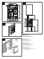 2
2
-
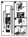 3
3
-
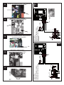 4
4
-
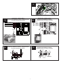 5
5
-
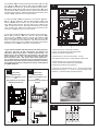 6
6
-
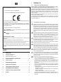 7
7
-
 8
8
-
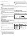 9
9
-
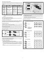 10
10
-
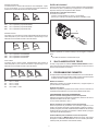 11
11
-
 12
12
-
 13
13
-
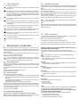 14
14
-
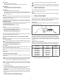 15
15
-
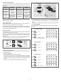 16
16
-
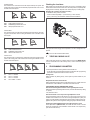 17
17
-
 18
18
-
 19
19
-
 20
20
-
 21
21
-
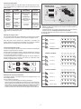 22
22
-
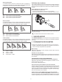 23
23
-
 24
24
-
 25
25
-
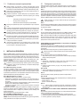 26
26
-
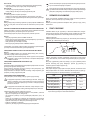 27
27
-
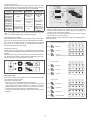 28
28
-
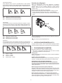 29
29
-
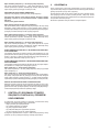 30
30
-
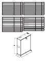 31
31
-
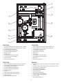 32
32
-
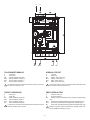 33
33
-
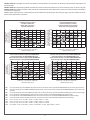 34
34
-
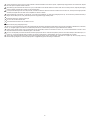 35
35
-
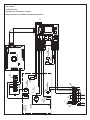 36
36
-
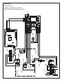 37
37
-
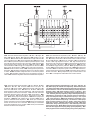 38
38
-
 39
39
-
 40
40


Beretta CONNECT BT LE Installer And User Manual
- Typ
- Installer And User Manual
- Niniejsza instrukcja jest również odpowiednia dla
w innych językach
- italiano: Beretta CONNECT BT LE
- français: Beretta CONNECT BT LE
- English: Beretta CONNECT BT LE
Inne dokumenty
-
DAB EVOPLUS SMALL 40/180 XM Instruction For Installation And Maintenance
-
 Elicent AXC Instrukcja obsługi
-
Ferroli KALIS 24 C – 34 C Caldera Bluehelix Hitech RRT Instrukcja instalacji
-
DAB E.SYBOX Instruction For Installation And Maintenance
-
Rehau 6-Zone Pump Relay Control Product Instructions
-
DeLOCK 60249 Karta katalogowa
-
DeDietrich MS 24 MI FF Instrukcja obsługi
-
 Purmo Euro Pump Unit Instrukcja obsługi
-
-
Ariston Andris Instrukcja obsługi

