Classic Exhibits VK-1089 Setup Instructions
- Typ
- Setup Instructions

www.classicexhibits.com
Step 1
Page 1 of 3
866.652.2100
© 2012
WHEN DISASSEMBLING ALUMINUM EXTRUSION, TIGHTEN ALL
SETSCREWS AND LOCKS TO PREVENT LOSS DURING SHIPPING
Order #XXXXX -
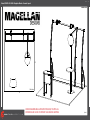
VK-1089 - Magellan Miracle - General Layout
10’
10’
Plan View

www.classicexhibits.com
Step 2
Page 2 of 3
866.652.2100
© 2012
WHEN DISASSEMBLING ALUMINUM EXTRUSION, TIGHTEN ALL
SETSCREWS AND LOCKS TO PREVENT LOSS DURING SHIPPING
Order #XXXXX - General Information
Using You Set-up Instructions:
The Visionary Designs Set-up Instructions for Magellan displays are created
specifically for your configuration. They are laid out sequentially, including an
exploded view of the entire display and a logical series of detailed steps for
assembly. We encourage you to study the instructions before attempting to
assemble your exhibit.
THIS IS VERY IMPORTANT!
Each page reminds you to tighten the setscrews after disassembling your
exhibit to prevent loss of the locks and setscrews (see below in red).
Cleaning & Packing Your Display:
1) Use care when cleaning aluminum extrusions or acrylic inserts. Use only
non-abrasive cleaners.
2) When cleaning laminate inserts or counter tops, use mild cleansers and
a soft material such as cotton.
3) Keep all display components away from extreme heat and long exposure
to sunlight to avoid warping and fading.
4) Retain all packing materials. It will make re-packing much easier and will
reduce the likelihood of shipping damage.
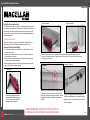
Hex Key Tool
Typical Connection Typical Connection
Most visionary design exhibits can
be assembled with the supplied Hex
Key Tool. Occasionally, a flat head
screwdriver may be required.
Detail A: Most horizontal extrusion connections have a patented expandable lock. This lock inserts into
the groove of an opposing extrusion. Tightening the lock with the Hex Key Tool expands the lock and creates
a strong positive connection.
Numbered
Label
Detail B: Each extrusion contains a numbered label that
corresponds to set-up instructions. The label is located
within a groove of the extrusion (when possible). Visionary
Design labels contain Black numbers unless otherwise
specified.
Horizontal Connection
Detail C: A rectangular connection bar with plastic
T Knobs is inserted between two horizontal extrusions
joined end-to-end. Turn the knobs clockwise to tighten.
Do Not Overtighten.

www.classicexhibits.com
Step 1
Page 1 of 3
866.652.2100
© 2012
WHEN DISASSEMBLING ALUMINUM EXTRUSION, TIGHTEN ALL
SETSCREWS AND LOCKS TO PREVENT LOSS DURING SHIPPING
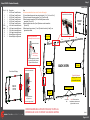
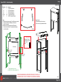
Order #XXXXX - Backwall Assembly
GREEN STAR indicates location
of connection lock with knob.
Knob
**Do not over tighten Knobs.**
RED STAR indicates location
of connection bar knob.
Turn Knob Clockwise
to Tighten Lock
Rear View of Display
**Do not over tighten Knobs.**
Knob
Knob
Connection
Bar
1
2
3
4
5
6
7a
8a
9
10
11
Part #
1
2
3
4
5
6
7a/7b
8a/8b
9
10
11
12
Qty
1
1
1
1
1
1
1/1
1/1
1
1
1
1
Description
48.5”h Lower Curved Extrusion
48.5”h Upper Curved Extrusion
48.5”h Lower Curved Extrusion
48.5”h Upper Curved Extrusion
48.5”h Lower Curved Extrusion
48.5”h Upper Curved Extrusion
44”w Lower Horizontal Extrusion
44”w Upper Horizontal Extrusion
23”w Lower Horizontal Extrusion
23”w Upper Horizontal Extrusion
Backwall Support Leg Extrusion
Backwall Support Leg Extrusion
Steps
Unit can be assembled face down on the floor then lifted upright.
1)
Connect backwall upper and lower verticals together [ 1 to 2, 3 to 4 and 5 to 6].
2) Connect horizontal extrusions together [7a to 7b and 8a to 8b].
3) Attach horizontal assemblies [7a/7b and 8a/8b] between vertical
assemblies [1/2 and 3/4].
4) Attach horizontal extrusions [9 and 10] between vertical assemblies
[3/4 and 5/6].
5) Attach support leg extrusions [11 and 12] to back of verticals [1 and 5], see
leg attachment detail.
7b
8b
A
A
A
B
B
12
Note: Slide connection
bar between extrusions and
tighten knobs to secure.
Velcro at top of bar
Velcro at
top of bar
Velcro at bottom of bar
Velcro at left
& right of bar Velcro at
left of bar
Velcro at
right of bar
Graphic Attachment
Apply graphic to back
of assembled backwall.
FRONT
VIEW
BACK
VIEW
BACK VIEW
Keep assembled
when shipping
Backside of backwall
Connect support leg to vertical
by placing lock into slot and
tighten with Allen Wrench.
Support Leg Attachment
(If accidentally removed from vertical)
Velcro at
bottom of bar

www.classicexhibits.com
Step 2
Page 2 of 3
866.652.2100
© 2012
WHEN DISASSEMBLING ALUMINUM EXTRUSION, TIGHTEN ALL
SETSCREWS AND LOCKS TO PREVENT LOSS DURING SHIPPING
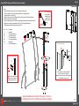
Order #XXXXX -
Header and Backwall Counter Assembly
Item
13
14a
14b
15
15a
15b
16
Description
Base Plate
47”h Vertical Extrusion
47”h Vertical Extrusion
37”h Vertical Extrusion
6”w Horizontal Extrusion
Flange Plate
42”w Vertical Extrusion
Qty.
1
1
1
1
1
1
1
Steps:
1) Attach vertical extrusions [14a,15] to base plate [13] with screws.
2) Connect verticals [14a and 15] with horizontal extrusion [15a] and attach
flange plate [15b] to vertical [15].
3) Slide counter top onto vertical [14a] and screw to flange plate [15b] with thumbscrews.
4) Attach vertical [14b] to vertical [14a].
5) Connect assembled vertical [14a/14b] to assembled backwall with horizontal extrusion [16].
6) Attach circular graphic to assembled vertical [14a/14b] using standoff screws.
7) Attach lights to assembled backwall where desired.
13
14a
14b
15
15a
16
Light Connection
Attach lights to
backwall where
desired and
tighten in place.
Graphic
Cap
Standoff
Barrel
Slide connector on back of standoff
barrels into groove of extrusion
and twist to secure in place. Secure graphic
to standoffs using screw caps.
Graphic Attachment
Screw
15b
*
*
*
*
Monitor Mount Attachment
Connectors
Attach monitor mount back
plate to connectors using
setscrews provided.

www.classicexhibits.com
Step 3
Page 3 of 3
866.652.2100
© 2012
WHEN DISASSEMBLING ALUMINUM EXTRUSION, TIGHTEN ALL
SETSCREWS AND LOCKS TO PREVENT LOSS DURING SHIPPING
Order #XXXXX -
Pedestal Assembly
Part Number
17
18
19
20
21/21a
22
Qty
1
1
1
1
4/2
2
Description
37.5”h Vertical Extrusion
37.5”h Corner Extrusion
37.5”h Corner Extrusion
37.5”h Vertical Extrusion
11”w Horizontal Extrusion
24.875”w Horizontal Extrusion
Steps
1)
Attach horizontal extrusions [21 and 21a] between vertical
extrusions [17&18 and 19&20], see Top View for
extrusion orientation.
2) Attach curved horizontal extrusions [22] between
corner extrusions [18 and 19], placing insert between
curved horizontals.
Sintra Insert
17
18
19
20
21a
21
22
22
21
21a
21
21
Top View
17
18 19
20
22
21 21
Shelf
Steps (Cont’d):
3) Place shelf atop lip of extrusions.
4) Set counter top atop assembled base.
Counter
Extrusions 21a and
22a have a lip for the
floor to rest
upon.
Lip for Shelf
Placement
Lip for Shelf
Placement
Lip
Extrusion Details:
**** Side assemblies must stay
assembled when shipping in jigged case

www.classicexhibits.com
866.652.2100
© 2011
WHEN DISASSEMBLING ALUMINUM EXTRUSION, TIGHTEN ALL
SETSCREWS AND LOCKS TO PREVENT LOSS DURING SHIPPING
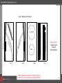
Order #XXXXX - Packing Instructions - Case 1
Extrusion 9 &10
Extrusion 7a, 7b, 8a, 8b and 16
Extrusion 4, 5, 6
Case 1: Backwall Components
Additional Items:
Halogen Lights
Graphics
Setup Hardware
Extrusion 1, 2, 3
Extrusion 11
Extrusion 12
Extrusion 14a, 14b, and 15
Counter Top
Base
Level 1 Level 2 Level 3
Level 4
15a

www.classicexhibits.com
866.652.2100
© 2012
WHEN DISASSEMBLING ALUMINUM EXTRUSION, TIGHTEN ALL
SETSCREWS AND LOCKS TO PREVENT LOSS DURING SHIPPING
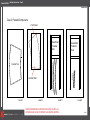
Order #XXXXX - Packing Instruction - Case 2
Case 2: Pedestal Components
Level 1 Level 2 Level 3 Level 4
Front Insert
Internal Shelf
Counter Top
Curved Extrusions # 22
Assembled
Pedestal
Side
Assembled
Pedestal
Side
21(2)
-
 1
1
-
 2
2
-
 3
3
-
 4
4
-
 5
5
-
 6
6
-
 7
7


Classic Exhibits VK-1089 Setup Instructions
- Typ
- Setup Instructions
w innych językach
- English: Classic Exhibits VK-1089
Powiązane artykuły
-
Classic Exhibits VK-2094 Setup Instructions
-
-
-
-
-
-
-
-
-