
M12 x 1
27
O
12
60PL
PCL
6
O
Baumer Electric AG
Hummelstrasse 17
CH − 8501 Frauenfeld
( +41 (0) 52 728 11 55
Weitere Baumer-Kontakte finden Sie unter:
For further Baumer contacts go to:
Autres contacts Baumer sous :
Ulteriori informazioni di contatto Baumer sono
disponibili al seguente indirizzo:
Encontrará otros contactos de Baumer en:
Dalsze informacje kontaktowe do firmy Baumer
znajdują się na stronie:
Адреса других представительств Baumer:
www.baumer.com
PCL
M12 x 1
27
O
12
60915PL
6
O
SW 22
M18 x 1.5
SAP NR. 90159
DE
|
EN
|
FR
|
IT
|
ES
|
PL
|
RU
DE
Änderungen vorbehalten
Right of modifications reserved
Modifications réservées
Con riserva di modifiche
Reservado el derecho a efectuar modificaciones
Zastrzegamy sobie prawo do wprowadzania zmian
Возможны изменения
03.08.2017
Strömungssensoren mit IO-Link / mit 2 Analogausgängen
Flow Sensors with IO-Link / with 2 analog outputs
Capteurs de débit avec IO-Link / avec 2 sorties analogiques
Sensori di flusso con IO-Link/2 uscite analogiche
Sensores de flujo con IO-Link / con 2 salidas analógicas
Czujnik przepływu ze złączem IO-Link / 2 wyjścia analogowe
Датчики потока с IO-Link или 2 аналог. выходами
Die ausführliche Betriebsanleitung ist unter www.baumer.com zum
Download verfügbar und nachzulesen. / Complete operating instructions
are available for download and reading at www.baumer.com. / La
notice d’instructions détaillée est disponible en téléchargement sous
www.baumer.com./Le istruzioni operative complete sono disponibili
per il download e la consultazione all’indirizzo www.baumer.com./
Las instrucciones de uso detalladas están disponibles para su descarga
y consulta en www.baumer.com./ Szczegółowa instrukcja obsługi
dostępna jest do przeczytania i pobrania na stronie www.baumer.com./
Подробное руководство по эксплуатации можно скачать на сайте
www.baumer.com.
PF20S
PF20H
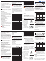
Anschlussbilder
Connection Diagrams
Schémas de raccordement
Schemi di collegamento
Esquemas de conexión
Schemat połączeń
Схемы электрических соединений
Informationen zu dieser Anleitung
• Diese Anleitung gilt für die Produkte PF20S und PF20H.
• Sie ermöglicht den sicheren und effizienten Umgang mit
dem Produkt.
• Diese Anleitung ist Teil des Produkts und muss während
der gesamten Lebensdauer aufbewahrt werden.
• Außerdem müssen die örtlichen Unfallverhütungsvor-
schriften und die nationalen Arbeitsschutzbestimmungen
beachtet werden.
• Das Produkt unterliegt der technischen Weiterentwicklung,
so dass Hinweise und Informationen in dieser Betriebs-
anleitung ebenfalls der Änderungen unterliegen können.
Die aktuelle Version finden Sie unter www.baumer.com im
Download-Bereich des Produktes.
HINWEIS!
Die Betriebsanleitung muss vor Gebrauch sorgfältig
gelesen und für späteres Nachschlagen aufbewahrt
werden.
Bestimmungsgemäße Verwendung
Dieser Sensor misst die Fließgeschwindigkeit wässriger
Medien in geschlossenen Rohrsystemen.
Der Baumer-Strömungssensor arbeitet nach dem
kalori metrischen Messprinzip. Dies ermöglicht es neben der
Fließgeschwindigkeit ebenfalls die Medientemperatur zu über-
wachen. Der Sensor erfasst die Änderungen beider Prozess-
kennwerte und wandelt diese in ein elektrisches Signal um.
PF20x-xx1xx mit IO-Link:
Die Sensoren können über IO-Link parametriert und auf die
jeweilige Anwendung angepasst werden. Je nach Einstellung
und Anschluss stehen zwei Schaltausgänge oder 1 Schalt-
und 1 Analogausgang (4...20 mA/ 0...10 V) zur Verfügung.
PF20x-xx0xx 2 mal analog:
Der Sensor verfügt über 2 Analogausgänge (4...20 mA).
Nicht bestimmungsgemäße Verwendung
• Keine Sicherheitsbauteile gemäß der Richtlinie 2006/42 EG
(Maschinenrichtlinie).
• Das Produkt ist nicht für den Einsatz in explosions gefähr-
deten Bereichen geeignet.
• Das Produkt darf ausschließlich mit Zubehör von Baumer
oder mit von Baumer freigegebenem Zubehör verwendet
oder mit zugelassenen Produkten kombiniert werden.
Eine Liste des freigegebenen Zubehörs und Kombinations-
produkten ist abrufbar unter www.baumer.com auf der
Produktdetailseite.
GEFAHR!
Gefahr von Personen- oder Sachschäden bei
nicht bestimmungsgemäßer Nutzung!
Die bestimmungswidrige Verwendung kann zu
gefährlichen Situationen führen.
– Die Angaben zur bestimmungsgemäßen
Verwendung beachten.
Qualifikation des Personals
• Eine geeignete technische Ausbildung wird vorausgesetzt.
• Eine elektrotechnische Unterweisung im Unternehmen ist nötig.
• Das Fachpersonal benötigt (dauerhaften) Zugriff auf die
Betriebsanleitung.
GEFAHR!
Gefahr von Personen- oder Sachschäden bei
nicht sachgemäßer Inbetriebnahme und Wartung!
Schäden an Personal und Ausrüstung möglich.
– Zureichende Unterweisung und Qualifikation des
Personals.
Allgemeine Sicherheitshinweise
• Für die sichere Inbetriebnahme muss die umfassende.
Betriebsanleitung verwendet werden. Die jeweils aktuelle
Version finden Sie unter www.baumer.com im Download-
Bereich des Produktes.
• Die Betriebsanleitung vor Gebrauch des Produkts sorgfältig
durchlesen.
• Den Sensor vor Verunreinigungen und mechanischen
Einwirkungen schützen.
• Die Installation und Demontage des Produkts darf nur in
drucklosen und abgekühlten Rohrsystemen erfolgen.
Technische Daten
Bestellnummer
Technische Daten
PF20x-xx1xx PF20x-xx0xx
Sensorspezifische Daten
Messbereich Flow (im Medium-
temperaturbereich −25…125 °C)
10...400 cm/s
Einstellbereich Flow 10...400 cm/s —
Messbereich Temp −25…150 °C
Einstellbereich Temp −25…150 °C —
Medium Wasser
Messabweichung Flow/Temp 2 %/ ±1°C
Umgebungsbedingungen
Mediumstemperatur −25…150 °C
Umgebungstemperatur −25…80 °C
Elektrische Daten
Versorgungsspannung 12...32 V DC
Anzahl Schaltausgänge 2 —
Schaltstrom Schaltausgang 100 mA —
Spannungsabfall Schaltausgang < 1,5 V —
Anzahl Analogausgänge 1 2
Analogausgang
4...20 mA /
0...10 V
4...20 mA
Schutzklasse III
Schnittstelle IO-Link 1.1 —
Mechanische Daten
Material Gehäuse Edelstahl 1.4404
Medienberührende Werkstoffe Edelstahl 1.4404
Schutzart IP68, IP69K
Anschlussart M12×1, 4-polig
Länge der Anschlussleitung max. 30 m
Ausgangsfunktion
PNP/NPN/Gegentakt programmierbar ja —
Öffner/Schließer umschaltbar ja —
Bestellnummer
Technische Daten
PF20x-xx1xx PF20x-xx0xx
Schaltausgang Flow/Temp umschaltbar ja —
Analogausgang Flow/Temp umschaltbar ja —
Analogausgang Strömung O2
Analogausgang Temperatur O1
Anschlussbild 139 141
Weitere Technische Daten sind auf dem Datenblatt und der
ausführlichen Betriebsanleitung des Sensors nachzulesen.
VORSICHT!
Gefahr von Personen- oder Sachschäden bei
Nichtbeachtung der Druckfestigkeit.
– Druckfestigkeit aller Komponenten im System
beachten. Druckfestigkeit im Datenblatt bezieht sich
auf Sensorstab. Druckfestigkeit des Systems ist u.a.
von den verwendeten Befestigungskomponenten
(Adapter) abhängig und maximal so hoch wie der
angegebene Wert für die schwächste Komponente.
Lieferumfang
• Strömungssensor PF20S oder PF20H
• Quickstart
Montage
• Das Produkt bei der Montage vor Verunreinigung schützen.
• Entsprechende elektrische sowie mechanische Vorschriften,
Normen und Sicherheitsregeln sind zu beachten.
• Das Produkt vor mechanischen Einwirkungen schützen.
• Auf mechanisch feste Montage des Sensors achten.
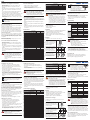
Einbauhinweise
Bedingungen zur korrekten Erfassung der Strömungs-
geschwindigkeit:
Für die korrekte Erfassung der
Strömungsgeschwindigkeit ist
die optimale Position der Mess-
spitze die Mitte des Rohres.
D
D/2
Für die korrekte Erfassung
der Strömungsgeschwindig
-
keit ist ausreichend Abstand
zu Querschnittsänderungen
und Rohrbögen zu halten.
5×D 3×D
Sensoren in geschlossen
Systemen und Steigleitungen
einbauen, in nach unten offe
-
nen Rohren ist die Erfassung
der Strömungsgeschwindig
-
keit fehlerhaft.
HINWEIS!
• Auf der Hülse des Sensors befindet
sich eine Markierung (siehe Abb.).
• Diese ist die Referenz (Startpunkt)
für die Prozessanschlusslänge
(siehe Datenblatt) und hilft den Sensor
korrekt im Rohrsystem zu positionieren.
Elektrischer Anschluss
• Den Sensor an 12…32 V DC anschließen.
Bei Betrieb mit IO-Link:
• Es muss ein IO-Link-Master mit Port Class A verwendet
werden, da bei Port Class A Pin 5 nicht angeschlossen ist.
• Bei größeren Störeinflüssen sollte eine geschirmte Leitung
verwendet werden.
Auslieferungszustand
PF20x-xx1xx PF20x-xx0xx
Funk-
tion
A1/01
(Pin 4)
Ausgang Schaltausgang Analogausgang
Physikalische Größe Strömung Temperatur
Ausgangsfunktion PNP NO 4…20 mA
Schaltpunkt 1 /
Start Analog
2 m/s −25 °C
Schaltpunkt 2 /
Ende Analog
1,5 m/s 150 °C
Funk-
tion
A2/02
(Pin 2)
Ausgang Analogausgang Analogausgang
Physikalische Größe Strömung Strömung
Ausgangsfunktion Strom 4…20 mA Strom 4…20 mA
Start Analog 0 m/s 0 m/s
Ende Analog 4 m/s 4 m/s
GEFAHR!
Gefahr von Personen- oder Sachschäden durch
elektrischen Strom!
Durch spannungsführende Teile sind Schäden an
Personal und Ausrüstung möglich.
– Anschluss des elektrischen Gerätes darf nur durch
entsprechendes Fachpersonal vorgenommen werden.
– Anschluss nur an SELV- und PELV-Systeme.
Rücksendung
• Aufgrund der gesetzlichen Vorschriften und zum Schutz der
Mitarbeiter, benötigt die Baumer AG die unterschriebene
Dekontaminationserklärung, bevor ihr Auftrag bearbeitet
werden kann.
• Das Formular ist unter www.baumer.com zu finden.
Umweltgerechte Entsorgung
Die Baumer AG nimmt unbrauchbare oder irreparable
Produkte nicht zurück. Bei der Entsorgung der Produkte
gelten jeweils gültigen länderspezifischen Vorschriften zur
Abfallentsorgung.
EU-Konformitätserklärung / EU Declaration
of Conformity / Déclaration UE de conformité/
Dichiarazione di conformità CE / Declaración
de conformidad CE / Deklaracja zgodności UE /
Заявление о соответствии требованиям ЕС
Die EU-Konformitätserklärung finden Sie unter
www.baumer.com im Download-Bereich des Produktes. /
The EU declaration of conformity can be found on our website
at www.baumer.com in download area. / Vous trouverez la dé-
claration UE de conformité sur www.baumer.com, dans la zone
de téléchargement du produit. / La Dichiarazione di conformi-
tà CE è disponibile all’indirizzo www.baumer.com, nell’area di
download del prodotto. / Encontrará la declaración de confor-
midad CE en www.baumer.com en la sección de descargas
del producto. / Deklarację zgodności UE można znaleźć na
stronie www.baumer.com w części do pobrania. / Заявление
о соответствии требованиям ЕС можно скачать по адресу
www.baumer.com на странице изделия.
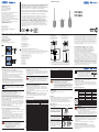
PL: Stablänge / Probe Length / Longueur de tige / Lunghezza della sonda /
Largo de la varilla / Długość pręta / Длина технологического соединения
PCL: Prozessanschlusslänge / Process Connection Lengthg / Longueur du raccord
procédé / Lunghezza connessione a processo / Longitud de la conexión a
proceso / Przyłącze procesowe / Длина технологического соединения
Schneid-Klemmring
Cutting/locking ring
Bague coupante/de serrage
Anello di bloccaggio/tagliente
Anillo de corte/de apriete
Pierścień izolacyjny
Срезное зажимное кольцо
Dichtkegel M18
Sealing cone M18
Cône d’étanchéité M18
Cono di tenuta M18
Cono de estanqueidad M18
Stożek uszczelniający M18
Уплотняющий конус
Andere Prozessanschlüsse siehe Produktselektor (www.baumer.com). Die Gehäuse -
abmessungen sind im jeweiligen Datenblatt zu finden. / See the product selector
for other process connections (www.baumer.com). Overall housing dimensions are
included in the respective data sheet. / Pour d‘autres raccords de process, se référer
au sélecteur de produits (www.baumer.com). Les dimensions du boîtier sont indiquées
dans les fiches techniques correspondantes. / Per ulteriori connessioni di processo
consultare il selettore prodotti (www.baumer.com). Le dimensioni del corpo sono
riportate nella corrispondente scheda tecnica. / Otros conectores al proceso, consulte
el selector de productos (www.baumer.com). Encontrará las dimensiones de la
carcasa en la hoja de datos correspondiente. / Pozostałe przyłącza procesowe można
znaleźć w wyszukiwarce produktów (www.baumer.com). Wymiary obudowy podano
na poszczególnych arkuszach z danymi technicznymi./ Прочие технологические
соединения см. в классификаторе продукции (www.baumer.com). Размеры корпуса
указаны в техпаспорте изделия.
+ Versorgungsspannung „+“
Supply Voltage “+”
Tension d’alimentation « + »
Tensione di alimentazione « + »
Tensión de alimentación « + »
Napięcie zasilania „+“
Напряжение питания “+”
– Versorgungsspannung „0 V“
Supply Voltage “0 V”
Tension d’alimentation « 0 V »
Tensione di alimentazione « 0 V »
Tensión de alimentación « 0 V »
Napięcie zasilania „0 V“
Напряжение питания “0 V”
A/
/ Schaltausgang Schließer (NO)/Schaltausgang Öffner (NC)/IO-Link
Switching Output (NO)/Switching Output (NC)/IO-Link
Sortie TOR, contact à fermeture (NO)/Sortie TOR, contact à ouverture (NC)/IO-Link
Uscita di commutazione contatto aperto (NO)/Uscita di commutazione contatto chiuso (NC)/IO-Link
Salida de conmutación contacto de cierre (NO)/Salida de conmutación contacto abierto (NC)/IO-Link
Zestyk zwierny wyjścia przełączającego (NO)/Zestyk rozwierny wyjścia przełączającego (NC)/IO-Link
Коммут. выход с замыканием (NO)/Коммут. выход с размыканием (NC)/IO-Link
T/SY Teach-in-Eingang/Synchronisation
Teach Input/Synchronization
Entrée d’apprentissage/Synchronisation
Entrée d’apprentissage/Synchronisation
Entrada teach/Sincronización
Wejście Teach-in/ synchronizacja
Вход обучения/синхронизации
O Analogausgang
Analog output
Sortie analogique
Uscita analogica
Salida analógica
Wyjście analogowe
Аналоговый выход

EN
FR
EN
FR
Information Concerning these Instructions
• These instructions apply to the products with ID codes
PF20S und PF20H.
• They make it possible to use the product safely and
efficiently.
• These instructions are an integral part of the product and
must be kept on hand for the entire duration of its service
life.
• Local accident prevention regulations and national work
safety regulations must be complied with as well.
• The product is subject to further technical development, and
thus the information contained in these operating instruc-
tions may also be subject to change. The current version
can be found at www.baumer.com in the product’s separate
download area.
NOTE!
The operating instructions must be read carefully
before using the product and must be kept on hand
for later reference.
Use for Intended Purpose
This sensor measures the flow velocities of oily and aqueous
media in closed piping systems.
The Baumer Flow Sensor functions in accordance with the
calorimetric measuring principle. This makes it possible to
monitor the temperature of the medium in addition to the
flow rate. The sensor detects changes to both characteristic
process values and converts them into an electrical signal.
PF20x-xx1xx with IO-Link:
The sensor’s parameters can be configured via IO-Link and
adapted to the respective application. Either 2 switching out-
puts, or 1 switching output and 1 analog output (4…20 mA /
0…10 V) are available depending on settings and connection
configuration.
PF20x-xx0xx 2-fold analog:
The sensor is equipped with 2 analog outputs (4…20 mA).
Use for Other than the Intended Purpose
• Not a safety component in accordance with 2006/42/EC
(Machinery Directive).
• The product is not suitable for use in potentially explosive
atmospheres.
• The product may only be used with accessories supplied
or approved by Baumer, or in combination with approved
products.
A list of approved accessories and combination products
can be accessed at www.baumer.com on the product
detail page.
DANGER!
Risk of personal injury or property damage in
case of use for other than the intended purpose!
Use for other than the intended purpose may lead
to hazardous situations.
– Observe instructions regarding use for intended
purpose.
Personnel Qualifications
• Suitable technical training is a prerequisite.
• In-house electronics training is required.
• Trained personnel must have uninterrupted access
to the operating instructions.
DANGER!
Risk of personal injury or property damage in case
of incorrect initial start-up and maintenance!
Personal injury and damage to equipment may occur.
– Adequate training and qualification of personnel.
General Safety Precautions
• The complete operating instructions must be used for safe
initial start-up. The respectively current version can be found
at www.baumer.com in the product’s separate download
area.
• Read the operating instructions carefully before using the
product.
• Protect the sensor against contamination and mechanical
influences.
• Installation and removal of the product is only permissible
in pressure-free piping systems which have been allowed
to cool down.
Technical Data
Order Number
Technical Data
PF20x-xx1xx PF20x-xx0xx
Sensor-Specific Data
Measuring range, flow (within a media
temperature range of −25 to 125° C)
10…400 cm/s
Setting range, flow 10…400 cm/s —
Measuring range, temperature −25 … 150 °C
Setting range, temperature −25…150° C —
Medium Water
Measurement error, flow/temperature 2 % / ±1 °C
Ambient Conditions
Media temperature −25…150 °C
Ambient temperature −25…80 °C
Electrical Data
Supply power 12…32 V DC
Number of switching outputs 2 —
Switching output switching current 100 mA —
Switching output voltage drop < 1.5 V —
Number of analog outputs 1 2
Analog output
4…20 mA /
0…10 V
4…20 mA
Protection class III
Interface IO-Link 1.1 —
Mechanical Data
Housing material Stainless steel 1.4404
Media contacting materials Stainless steel 1.4404
Protection IP68, IP69K
Connector type M12×1, 4-pin
Connection cable length up to 30 m
Output Function
Configurable as PNP, NPN or push-pull Yes —
Can be switched to NC or NO operation Yes —
Switching output, flow/temperature Yes —
Order Number
Technical Data
PF20x-xx1xx PF20x-xx0xx
Analog output, flow/temperature Yes —
Analog flow rate output O2
Analog temperature output O1
Wiring diagram 139 141
Further technical data can be found in the data sheet and in
the sensor’s complete operating instructions.
CAUTION!
Risk of personal injury or property damage in
case of non-compliance with pressure resistance
specification!
– Observe pressure resistance of all components
within the system. In the data sheet, the pressure
resistance entry makes reference to the sensor
rod. Amongst other factors, the pressure resistance
of the system depends on the utilized mounting
components (adapters), and is only as high as the
pressure resistance of the weakest component.
Scope of Delivery
• PF20S or PF20H flow sensor
• Quick-start guide
Installation
• Protect the product from contamination during installation.
• Observe all applicable electrical and mechanical
regulations, standards, and safety rules.
• Protect the product against mechanical influences.
• Make sure that the sensor is mounted in a mechanically
secure fashion.
Mounting
Conditions for correct detection of the flow rate:
In order to correctly detect the
flow rate, the tip of the sensor
is positioned ideally in the
middle of the pipe.
D
D/2
Adequate distance from pipe
bends and points at which
cross-sections change must
be maintained in order to
correctly detect the flow rate.
5×D 3×D
Install sensors in closed
systems and riser pipes
because detection of the flow
rate is faulty in pipes which
are open at the bottom.
NOTE!
• There’s a marking on the
sensor’s sleeve (see figure).
• This is a reference point (starting
point) relative to the length of the
process connection (see data
sheet), and provides assistance in correctly
positioning the sensor within the piping system.
Electrical Connection
• Connect the sensor to 12 to 32 V DC.
When operated with IO-Link:
• An IO-Link master with class A port must be used because
pin 5 is not connected in the case of a class A port.
• In the case of excessive interference, a shielded cable
should be used.
Default Settings
PF20x-xx1xx PF20x-xx0xx
Func-
tion,
A1/01
(pin 4)
Output Switching output Analog output
Physical quantity Flow Temperature
Output function PNP NO 4 to 20 mA
Switching point 1 /
start analog
2 m/s −25° C
Switching point 2 /
end analog
1.5 m/s 150° C
Func-
tion,
A2/02
(pin 2)
Output Analog output Analog output
Physical quantity Flow Flow
Output function
Current: 4 …
20 mA
Current: 4 …
20 mA
Start analog 0 m/s 0 m/s
End analog 4 m/s 4 m/s
DANGER!
Risk of personal injury or property damage
due to electric current!
Voltage conducting parts may cause personal
injury or damage to equipment.
– The electric device may only be connected by
appropriately qualified personnel.
– Connect to SELV and PELV systems only.
Returns
• Due to legal regulations and for the protection of
employees, Baumer AG requires a signed declaration
of decontamination before processing your order.
• The corresponding form is available at www.baumer.com.
Proper Disposal
Baumer AG does not accept the return of unusable or
irreparable products. Respectively valid national waste
disposal regulations apply to product disposal.
Informations sur cette notice
• Cette notice concerne les produits PF20S et PF20H.
• Elle permet un maniement sûr et efficient du produit.
• Cette notice fait partie du produit et doit être conservée
pendant toute sa durée de vie.
• Il faut par ailleurs respecter les règlements locaux de
prévention des accidents et la réglementation nationale
sur la sécurité au travail.
• Le produit est soumis à une évolution technique, de sorte
que les remarques et les informations contenues dans cette
notice d’instructions peuvent également être sujettes à
modifications. La version actuelle se trouve sur
www.baumer.com, dans la zone de téléchargement du
produit.
REMARQUE !
La notice d’instructions doit être lue attentivement
avant l’emploi et conservée pour consultation
ultérieure.
Utilisation conforme
Ce capteur mesure la vitesse d’écoulement de fluides aqueux
dans des systèmes fermés de conduits.
Le capteur de débit de Baumer fonctionne selon le principe
de mesure calorimétrique. Il permet de surveiller la tempéra-
ture du fluide, en plus de sa vitesse d’écoulement. Le capteur
détecte les variations des deux valeurs caractéristiques du
process et les convertit en signal électrique.
PF20x-xx1xx avec IO-Link :
Les capteurs peuvent être paramétrés via IO-Link et adaptés à
l’application respective. Selon leur réglage et leur raccorde-
ment, ils mettent à disposition 2 sorties TOR ou bien 1 sortie
TOR et 1 sortie analogique (4...20 mA/ 0...10 V).
PF20x-xx0xx 2 fois analogique :
Le capteur dispose de 2 sorties analogiques (4...20 mA).
Utilisation non conforme
• Le produit n’est pas un composant de sécurité au
sens de la directive 2006/42 CE (directive Machines)
• Le produit ne convient pas à une utilisation en
environnements à atmosphère explosible
• Le produit doit être uniquement utilisé avec des accessoires
de Baumer ou validés par Baumer ou combiné avec des
produits homologués.
Une liste des accessoires validés et des produits utilisables
en combinaison peut être consultée sur www.baumer.com
sur la page des détails du produit.
DANGER ! Risque de blessures ou de dommages
matériels en cas d’utilisation non conforme !
L’utilisation non conforme peut conduire à des
situations dangereuses.
– Respecter les indications sur l’utilisation conforme.
Qualification du personnel
• Une formation technique appropriée est requise.
• Une formation électrotechnique dans l’entreprise est
nécessaire.
• Le personnel qualifié nécessite un accès (permanent)
à la notice d’instructions.
DANGER ! Risque de blessures ou de dommages
matériels en cas de mise en service et de
maintenance incorrectes !
Blessures du personnel et endommagement de
l’équipement possibles.
– Formation et qualification suffisantes du personnel.
Consignes de sécurité générales
• Pour une mise en service sûre, il faut utiliser la notice d’instruc-
tions complète. La version actuelle respective se trouve sur
www.baumer.com, dans la zone de téléchargement du produit
• La notice d’instructions doit être lue attentivement avant
l’emploi du produit.
• Protéger le capteur des saletés et des effets mécaniques.
• L’installation et le démontage du produit ne doivent être
réalisés que dans des systèmes de conduits hors pression
et refroidis.
Caractéristiques techniques
N° de commande
Caractéristiques techniques
PF20x-xx1xx
PF20x-
xx0xx
Données spécifiques au capteur
Plage de mesure de débit (pour une
température du fluide de −25…125 °C)
10...400 cm/s
Plage de réglage de débit 10...400 cm/s —
Plage de mesure de température −25…150 °C
Plage de réglage de température −25…150 °C —
Fluide Eau
Écart de mesure débit/température 2 %/ ±1°C
Conditions ambiantes
Température du fluide −25…150 °C
Température ambiante −25…80 °C
Caractéristiques électriques
Tension d’alimentation 12...32 V c.c.
Nombre de sorties TOR 2 —
Courant commuté, sortie TOR 100 mA —
Chute de tension, sortie TOR < 1,5 V —
Nombre de sorties analogiques 1 2
Sortie analogique
4...20 mA /
0...10 V
4...20 mA
Classe de protection III
Interface IO-Link 1.1 —
Caractéristiques mécaniques
Matériau du boîtier Acier inoxydable 1.4404
Matériaux en contact avec les fluides Acier inoxydable 1.4404
Indice de protection IP68, IP69K
Type de raccordement M12×1, 4 contacts
Longueur du câble de raccordement max. 30 m
Fonction de sortie
PNP/NPN/push-pull programmables oui —
N° de commande
Caractéristiques techniques
PF20x-xx1xx
PF20x-
xx0xx
Commutable entre contact à ouverture/
fermeture
oui —
Sortie TOR débit/température commutable oui —
Sortie analogique débit/température
commutable
oui —
Sortie analogique, débit O2
Sortie analogique, température O1
Schéma de raccordement 139 141
D’autres caractéristiques techniques sont données dans la fiche
technique et dans la notice d’instructions complète du capteur.
PRUDENCE ! Risque de blessures ou de
dommages matériels si la résistance à la pression
n’est pas prise en compte.
– Tenir compte de la résistance à la pression de tous
les composants du système. La résistance à la
pression dans la fiche technique concerne la tige
du capteur. La résistance à la pression du système
dépend entre autres des composants utilisés pour la
fixation (adaptateur) et elle est au maximum égale à
la valeur indiquée pour le composant le plus faible.
Fournitures
• Capteur de débit PF20S ou PF20H
• Quickstart
Montage
• Protéger le produit de la saleté lors du montage.
• Respecter les prescriptions, normes et règles de sécurité
électriques ainsi que mécaniques applicables.
• Protéger le produit des effets mécaniques.
• Veiller à ce que le capteur soit solidement fixé.
Instructions de montage
Conditions pour une acquisition correcte de la vitesse
d’écoulement :
Pour l’acquisition correcte de la
vitesse d’écoulement, la position
optimale de la pointe de mesure est
au centre du tuyau.
D
D/2
Pour l’acquisition correcte de la
vitesse d’écoulement, respecter
une distance suffisante par rapport
aux changements de section et
aux coudes du tuyau.
5×D 3×D
Les capteurs doivent être montés
dans des systèmes et tuyaux de
montée fermés ; l’acquisition de la
vitesse d’écoulement est erronée
dans des tuyaux ouverts vers le bas.
REMARQUE !
• Une marque est apposée sur le tube
du capteur (voir figure).
• Elle sert de référence (point de départ)
pour la longueur du raccord procédé
(voir fiche technique) et aide à positionner correcte-
ment le capteur dans le système de conduits.
Raccordement électrique
• Raccorder le capteur à la tension 12…32 V c.c.
Fonctionnement avec IO-Link:
• Il convient d‘utiliser un maître IO-Link avec un port de
classe A, la broche 5 n‘y étant pas raccordée.
• En cas d’interférences plus importantes, il est recommandé
d’utiliser un câble blindé.
État à la livraison
PF20x-xx1xx PF20x-xx0xx
Fonc-
tion
A1/01
(broche
4)
Sortie Sortie TOR Sortie analogique
Grandeur physique Débit Température
Fonction de sortie PNP NO 4…20 mA
Point de
commu tation 1 /
début analogique
2 m/s −25 °C
Point de
commutation 2 /
fin analogique
1,5 m/s 150 °C
Fonc-
tion
A2/02
(broche
2)
Sortie Sortie analogique Sortie analogique
Grandeur physique Débit Débit
Fonction de sortie Intensité 4…20 mA Intensité 4…20 mA
Début analogique 0 m/s 0 m/s
Fin analogique 4 m/s 4 m/s
DANGER ! Risque de blessures ou de dommages
matériels par le courant électrique.
Blessures du personnel et endommagement de
l’équipement possibles par des pièces sous tension.
– Le raccordement électrique de l’appareil ne doit être
réalisé que par un personnel qualifié en conséquence.
– Raccordement uniquement à des systèmes TBTS et
TBTP.
Retour
• En raison des dispositions légales et pour la protection des
employés, Baumer AG doit disposer de la déclaration de
décontamination signée, avant de pouvoir traiter votre ordre.
• Le formulaire se trouve sur www.baumer.com Téléchar-
gement Conditions générales de vente (CGV) et retours.
Mise au rebut appropriée
La société Baumer AG ne reprend pas les produits inutili-
sables ou irréparables. Lors de la mise au rebut des produits,
respecter les réglementations nationales en vigueur sur
l’élimination des déchets.

SAP NR. 90160
IT
ES
Informazioni sulle presenti istruzioni
• Queste istruzioni si riferiscono al prodotto PF20S/PF20H.
• Di cui consentono un impiego efficiente e sicuro.
• Sono inoltre parte integrante della soluzione e devono
essere conservate per l'intero ciclo di vita del prodotto.
• In aggiunta alle presenti istruzioni, devono essere rispettate
le norme nazionali per la prevenzione degli infortuni e la
sicurezza sul lavoro.
• Il prodotto è soggetto a ulteriori sviluppi tecnici, pertanto
anche le indicazioni e le informazioni fornite in queste
istruzioni d'uso potrebbero subire modifiche. La versione
aggiornata del documento è disponibile all'indirizzo
www.baumer.com nell'area di download del prodotto.
NOTA
Prima dell'impiego del prodotto, leggere attentamen-
te le istruzioni per l'uso e conservarle per eventuali
successive consultazioni.
Impiego previsto
Questo sensore misura la velocità di scorrimento di sostanze
acquose in sistemi di tubazioni chiusi.
Il sensore di flusso Baumer funziona secondo il principio di
misurazione calorimetrico che, oltre alla velocità di scorri-
mento, permette di monitorare anche la temperatura della
sostanza. Il dispositivo rileva le modifiche di entrambi i valori
di riferimento di processo e le converte in segnali elettrici.
PF20x-xx1xx con IO-Link:
Il sensore può essere configurato tramite IO-Link e opportu-
namente adattato all'applicazione di destinazione. A seconda
dell'impostazione e del collegamento sono disponibili due
uscite di commutazione o un'uscita di commutazione e
un'uscita analogica (4-20 mA/ 0-10 V).
PF20x-xx0xx con 2 uscite analogiche:
Il sensore dispone di due uscite analogiche (4-20 mA).
Impiego non previsto
• Nessun componente di sicurezza conforme alla Direttiva
2006/42 CE (Direttiva Macchine).
• Il prodotto non è idoneo all'impiego in atmosfera
potenzialmente esplosiva.
• Il prodotto deve essere utilizzato esclusivamente con
accessori fabbricati o autorizzati da Baumer e associato
solo a prodotti approvati.
Un elenco degli accessori autorizzati e dei prodotti idonei
per l'impiego combinato è disponibile sulla pagina delle
informazioni dettagliate sul prodotto, all'indirizzo
www.baumer.com.
PERICOLO! In caso di impiego non a norma,
esiste il pericolo di lesioni personali o danni
materiali.
L'uso non conforme del prodotto può creare
situazioni rischiose.
– Seguire le indicazioni per l'impiego previsto.
Idoneità del personale
• Richiesta formazione tecnica adeguata.
• Richiesta esperienza in campo elettrotecnico in impresa.
• Il personale specializzato deve poter accedere stabilmente
alle istruzioni per l'uso.
PERICOLO! In caso di messa in funzione o
manutenzione non a regola d'arte, esiste il
pericolo di lesioni personali o danni materiali.
Possono verificarsi danni a persone e attrezzature.
– Verificare che il personale sia adeguatamente
addestrato e qualificato.
Informazioni di sicurezza generali
• Per una messa in funzione sicura, seguire tutte le istruzioni
per l'uso. La versione aggiornata del documento è
disponibile all'indirizzo www.baumer.com nella sezione
Download del prodotto.
• Leggere attentamente tali istruzioni prima di utilizzare il prodotto.
• Proteggere il sensore da contaminazioni e azioni meccaniche.
• Il montaggio e lo smontaggio del prodotto devono essere
eseguiti solo in sistemi di tubazioni raffreddati e privi di
pressione.
Specifiche tecniche
Numero d'ordine
Specifiche tecniche
PF20x-
xx1xx
PF20x-
xx0xx
Dati specifici del sensore
Campo di misurazione flusso (nella fascia di tem-
peratura della sostanza variabile da −25 a 125 °C)
10-400 cm/s
Campo di regolazione flusso 10-400 cm/s —
Campo di misurazione temp. −25-150 °C
Campo di regolazione temp. −25-150 °C —
Sostanza Acqua
Differenza di misurazione flusso/temp. 2%/ ±1 °C
Condizioni ambientali
Temperatura della sostanza −25-150 °C
Temperatura ambientale −25-80 °C
Dati elettrici
Tensione di alimentazione 12-32 V CC
Numero uscite di commutazione 2 —
Corrente di commutazione uscita di
commutazione
100 mA —
Caduta di tensione uscita di commutazione < 1,5 V —
Numero uscite analogiche 1 2
Uscita analogica
4-20 mA/0-
10 V
4-20 mA
Classe di protezione III
Interfaccia IO-Link 1.1 —
Dati meccanici
Materiale corpo Acciaio 1.4404
Materiale a contatto con le sostanze Acciaio 1.4404
Grado di protezione IP68, IP69K
Tipo di collegamento M12×1, 4 pin
Lunghezza del cavo di collegamento max 30 m
Funzione di uscita
Programmazione PNP/NPN/push-pull Sì —
Commutazione contatto chiuso/contatto aperto Sì —
Commutazione uscita di commutazione flusso/
temp.
Sì —
Commutazione uscita analogica flusso/temp. Sì —
Numero d'ordine
Specifiche tecniche
PF20x-
xx1xx
PF20x-
xx0xx
Uscita analogica flusso O2
Uscita analogica temperatura O1
Schema di collegamento 139 141
Per ulteriori informazioni tecniche, consultare la scheda
tecnica o le dettagliate istruzioni per l'uso del sensore.
ATTENZIONE! In caso di mancato rispetto delle
indicazioni relative alla resistenza alla pressione,
esiste il pericolo di lesioni personali o danni
materiali.
– Verificare la resistenza alla pressione di tutti i
componenti del sistema. La resistenza alla pressione
riportata nella scheda tecnica si riferisce alla sonda
del sensore. La resistenza alla pressione del sistema
dipende, tra le altre cose, dai componenti di fissag-
gio impiegati (adattatori) ed è pari al valore massimo
specificato specificato per i componenti più deboli.
Volume di consegna
• Sensore di flusso PF20S o PF20H
• Quickstart
Montaggio
• Proteggere il prodotto da contaminazioni durante il montaggio.
• Osservare le disposizioni elettriche e quelle meccaniche, le
norme e le regole di sicurezza.
• Proteggere il sensore da azioni meccaniche.
• Verificare che il montaggio del sensore sia meccanicamente
stabile.
Istruzioni di installazione
Condizioni per il corretto rilevamento della velocità di flusso:
Per il corretto rilevamento
della velocità di flusso, la
posizione ottimale della punta
di misura è il centro del tubo.
D
D/2
Per il corretto rilevamento
della velocità di flusso, è
necessario osservare una
distanza sufficiente per le
variazioni della sezione
trasversale e i tubi a gomito.
5×D 3×D
Installare i sensori in
condutture verticali e sistemi
chiusi. Nei tubi aperti verso
il basso, il rilevamento della
velocità di flusso non funziona
correttamente.
NOTA
• Sul manicotto del sensore è
presente una tacca (vedere la figura).
• Si tratta del contrassegno di riferimento
(punto iniziale) della lunghezza di
connessione processo (vedere la scheda tecnica) e
consente di posizionare correttamente il sensore nel
sistema di tubazioni.
Collegamento elettrico
• Collegare il sensore a fonti di 12-32 V CC.
In caso di impiego con IO-Link
• È necessario utilizzare un IO-Link master con Port
Class A, poiché con questa classe il pin 5 non è collegato.
• In caso di maggiori disturbi è consigliabile utilizzare
un cavo schermato.
Stato della consegna
PF20x-xx1xx PF20x-xx0xx
Fun-
zione
A1/01
(Pin 4)
Uscita
Uscita di com-
mutazione
Uscita analogica
Dimensione fisica Flusso Temperatura
Funzione di uscita PNP NO 4-20 mA
Punto di
commutazione 1 /
Inizio segnale
analogico
2 m/s −25 °C
Punto di commu-
tazione 2 / Fine
segnale analogico
1,5 m/s 150 °C
Fun-
zione
A2/02
(Pin 2)
Uscita Uscita analogica Uscita analogica
Dimensione fisica Flusso Flusso
Funzione di uscita
Corrente
4−20 mA
Corrente
4−20 mA
Inizio segnale
analogico
0 m/s 0 m/s
Fine segnale
analogico
4 m/s 4 m/s
PERICOLO! Pericolo di lesioni personali o danni
materiali per la presenza di corrente elettrica.
La presenza di componenti sotto tensione comporta
il rischio di danni a persone o attrezzature.
– Il collegamento del dispositivo elettrico deve essere
effettuato esclusivamente da personale specializzato.
– Collegamento solo a sistemi SELV e PELV.
Reso
• In conformità alle disposizioni di legge e per la protezione
del personale, Baumer AG richiede la dichiarazione di
decontaminazione firmata prima di poter elaborare l'ordine.
• L'apposito modulo può essere scaricato all'indirizzo
www.baumer.com.
Smaltimento conforme alle normative ambientali
Baumer AG non accetta la restituzione di prodotti inutilizzabili
o non riparabili. Per lo smaltimento del prodotto osservare le
direttive nazionali vigenti.
Información relativa a estas instrucciones
• Estas instrucciones son de aplicación para el producto
PF20x-11.xxx y PF20x-21.xxx.
• Permiten un manejo sencillo y eficiente del producto.
• Estas instrucciones forman parte del producto y deben
guardarse durante toda la vida útil de este.
• Además, hay que tener en cuenta la normativa en materia
de prevención de accidentes y las disposiciones nacionales
en materia de condiciones de trabajo.
• El producto está sometido a un proceso de mejora técnica
continuo, de igual manera que las instrucciones y la
información de estas instrucciones de uso están sujetas
a posibles modificaciones. Encontrará la versión actual
en www.baumer.com, en la sección de descargas del
producto.
¡NOTA!
Antes de nada, lea atentamente las instrucciones
de uso y consérvelas para consultas posteriores.
Utilización conforme a la finalidad de uso
Este sensor mide la velocidad de corriente de medios
acuosos en sistemas cerrados de tuberías.
El sensor de caudal de Baumer se basa en el principio
calorimétrico. Este permite controlar la velocidad de
caudal y la temperatura del medio. El sensor registra las
modificaciones de ambos parámetros y los convierte
en una señal eléctrica.
PF20x-xx1xx con IO-Link:
Los sensores pueden parametrizarse a través de IO-Link y
adaptarse a la aplicación correspondiente. En función del
tipo de configuración y de conexión hay disponibles 2 salidas
de conmutación, 1 salida de conmutación y 1 analógica
(4...20 mA/0...10 V).
PF20x-xx0xx 2 veces analógico:
El sensor dispone de 2 salidas analógicas (4...20 mA).
Utilización no conforme a la finalidad de uso
• Ningún componente de seguridad conforme a la Directiva
2006/42 EC (Directiva de máquinas).
• Este producto no es apto para el uso en atmósferas
potencialmente explosivas.
• Este producto ha de emplearse exclusivamente con
accesorios de Baumer o accesorios habilitados de Baumer
o combinarse con productos autorizados.
La lista de accesorios habilitados y productos combinados
se encuentra disponible en la página con información sobre
el producto en www.baumer.com.
¡PELIGRO! Riesgo de daños personales o
materiales en caso de utilización no conforme
a la finalidad de uso.
La utilización no conforme a la finalidad de uso
puede provocar situaciones de riesgo.
– Tenga en cuenta la información relativa a la
utilización conforme a la finalidad de uso.
Cualificación del personal
• Es condición indispensable contar con la formación técnica
adecuada.
• Es necesario impartir formación en electrotecnica en la
empresa.
• El personal especializado necesita acceso (permanente) a
las instrucciones de uso.
¡PELIGRO! Riesgo de daños personales o
materiales en caso de utilización no conforme
a la finalidad de uso.
Es posible que se produzcan daños personales y
daños en el equipamiento.
– Formación y cualificación suficiente del personal.
Aviso de seguridad general
• Para lograr una puesta en marcha segura, es necesario
consultar íntegramente las instrucciones de uso. Encontrará
la versión actual en www.baumer.com, en la sección de
descargas del producto.
• Leer atentamente el manual de instrucciones antes de
utilizar el producto.
• Es necesario proteger el sensor de los contaminantes y las
influencias mecánicas.
• La instalación y desinstalación del producto solo ha
de llevarse a cabo cuando el sistema de tuberías esté
despresurizado y en frío.
Datos técnicos
Número de pedido
Datos técnicos
PF20x-xx1xx
PF20x-
xx0xx
Datos del sensor
Rango de medición del flujo (en el rango de
temperatura del medio -25...125 °C)
10...400 cm/s
Distancia de ajuste Flujo 10...400 cm/s —
Rango de medición Temp −25…150 °C
Distancia de ajuste Temp −25…150 °C —
Medio Agua
Rango de medición Flujo/Temp 2 %/ ±1°C
Condiciones ambientales
Temperatura del medio −25…150 °C
Temperatura ambiente −25…80 °C
Datos eléctricos
Tensión de alimentación 12...32 V CC
Número de salidas de conmutación 2 —
Corriente de conmutación salida de conmutación 100 mA —
Caída de tensión salida de conmutación < 1,5 V —
Número de salida analógica 1 2
Salida analógica
4...20 mA /
0...10 V
4...20
mA
Categoría de protección III
Interfaz IO-Link 1.1 —
Datos mecánicos
Material de la Cubierta Acero inox 1.4404
Materiales en contacto con el medio Acero inox 1.4404
Clase de protección IP68, IP69K
Tipo de conexión M12×1, 4 polos
Longitud del cable de conexión máx. 30 m
Función de salida
Configurable PNP/NPN/Push-Pull sí —
Número de pedido
Datos técnicos
PF20x-xx1xx
PF20x-
xx0xx
Puede ajustarse en funcionamiento NC o NO sí —
Salida de conexión Flujo/Temp conmutable sí —
Salida analógica Flujo/Temp conmutable sí —
Salida analógica de flujo O2
Salida analógica de temperatura O1
Esquema de conexión 139 141
Es obligatorio consultar el resto de características técnicas de la
hoja de datos y las instrucciones de uso detalladas del sensor.
¡ATENCIÓN! Riesgo de daños personales o
materiales en caso de no tener en cuenta la
resistencia a la presión.
– Tenga en cuenta la resistencia a la presión de
todos los componentes del sistema. La resistencia
a la presión mencionada en la hoja de datos se
refiere a la varilla del sensor. La resistencia a la pre-
sión del sistema depende, entre otras cosas, de los
componentes de fijación (adaptadores) empleados
y ha de alcanzar como máximo el valor indicado
para el componente más débil.
Volumen de entrega
• Sensor de caudal PF20S o PF20H
• Instrucciones inicio rápido
Montaje
• Durante el montaje, proteger el producto contra impurezas.
• Deben observarse las correspondientes normativas, normas
y reglas de seguridad, tanto eléctricas como mecánicas.
• Proteger el producto de influencias mecánicas.
• Asegurarse de que el sensor esté montado mecánicamente fijo.
Instrucciones de instalación
Condiciones para el registro adecuado de la velocidad del flujo:
La posición óptima de la punta
de medición para conseguir un
registro fidedigno de la veloci-
dad de flujo es la parte central
de la tubería.
D
D/2
Para conseguir un registro
fidedigno de la velocidad de
flujo, es necesario mantener
una distancia suficiente hasta
los cambios de las secciones
transversales y los codos de
la tubería.
5×D 3×D
Montar los sensores en los
sistemas cerrados y las
tuberías verticales, con las
tuberías abiertas hacia abajo,
el registro de la velocidad del
flujo resulta incorrecto.
¡NOTA!
• En el manguito del sensor hay
una marca (ver imagen).
• Esta es la referencia (punto inicial)
de la longitud de la conexión a proceso
(ver hoja de datos) y ayuda a colocar
correctamente el sensor en el sistema de tuberías.
Conexión eléctrica
• Conectar el sensor a 12…32 V CC.
Funcionamiento con IO-Link
• Hay que utilizar un puerto IO-Link Master Clase A, ya
que en el puerto Clase A, el pin 5 no está conectado.
• En caso de perturbaciones significativas, sería necesario
utilizar un cable apantallado.
Estado de suministro
PF20x-xx1xx PF20x-xx0xx
Función
A1/01
(Pin 4)
Salida
Salida de
conmutación
Salida analógica
Magnitud física Flujo
Datos de
temperatura
Función de salida PNP NO 4…20 mA
Punto de
conmutación 1 /
Inicio analógico
2 m/s −25 °C
Punto de
conmutación 2 /
Extremo analógico
1,5 m/s 150 °C
Función
A2/02
(Pin 2)
Salida Salida analógica Salida analógica
Magnitud física Flujo Flujo
Función de salida
Corriente 4…20
mA
Corriente 4…20
mA
Inicio Analógico 0 m/s 0 m/s
Extremo analógico 4 m/s 4 m/s
¡PELIGRO! Riesgo de daños personales o
materiales debidos a la corriente eléctrica.
Las piezas sometidas a tensión pueden provocar
daños personales y daños en el equipamiento.
– La conexión del aparato eléctrico solo la debe llevar
a cabo el personal especialista correspondiente.
– Conexión exclusivamente a sistemas SELV y PELV.
Devolución
• En virtud de las disposiciones legales y para proteger a los
trabajadores, Baumer AG necesita firmada la declaración de
que el equipo ha sido descontaminado antes de procesar
la solicitud.
• Encontrará el formulario en www.baumer.com.
Eliminación respetuosa con el medio ambiente
Baumer AG no acepta la devolución de productos inutilizados
o irreparables. La eliminación de los productos se rige por las
normativas vigentes sobre eliminación de residuos del país.

PL
RU
O tej instrukcji obsługi
• Instrukcja ta dotyczy produktów PF20S i PF20H.
• Umożliwia ona bezpieczną i sprawną obsługę tego urządzenia.
• Instrukcja ta jest częścią produktu i należy przechowywać ją
przez cały okres eksploatacji.
• Ponadto należy przestrzegać lokalnych przepisów z zakresu
prewencji wypadkowej oraz krajowych przepisów prawa pracy.
• Produkt podlega rozwojowi technicznemu. W związku z
tym wskazówki i informacje zawarte w tej instrukcji obsługi
również mogą ulec zmianie. Aktualną wersję można pobrać
na stronie produktu w witrynie www.baumer.com.
WSKAZÓWKA!
Przed użyciem należy dokładnie przeczytać całą
instrukcję obsługi i zachować ją w celu wykorzystania
w przyszłości.
Stosowanie zgodne z przeznaczeniem
Czujnik ten mierzy natężenie przepływu mediów wodnych w
zamkniętych systemach rurowych.
Czujniki przepływu Baumer działają na zasadzie pomiaru
kolometrycznego. Poza mierzeniem prędkości przepływu
monitorują również temperaturę cieczy. Czujnik wykrywa
zmiany wartości obu parametrów procesu i konwertuje je
na sygnał elektryczny.
PF20x-xx1xx ze złączem IO-Link:
Parametry czujników można dostosować do dowolnego
zastosowania poprzez złącze IO-Link. W zależności od
ustawienia i połączenia dostępne są dwa wyjścia przełączające
lub 1 przełącznik i 1 wyjście analogowe (4...20 mA/0...10 V).
PF20x-xx0xx 2 razy analog:
Czujnik wyposażony jest w 2 wyjścia analogowe (4...20 mA).
Niewłaściwe użytkowanie
• Brak elementów bezpieczeństwa zgodnie z dyrektywą
2006/42 WE (dyrektywa maszynowa).
• Produkt nie nadaje się do stosowania w obszarach
zagrożonych wybuchem.
• Produkt można stosować wyłącznie z akcesoriami firmy
Baumer i akcesoriami przez nią zatwierdzonymi lub w
połączeniu z innymi zatwierdzonymi produktami.
Listę zatwierdzonych materiałów i kombinacji produktów
można pobrać ze strony www.baumer.com w części
poświęconej szczegółom produktu.
NIEBEZPIECZEŃSTWO!
Niebezpieczeństwo obrażeń ciała lub uszkodzeń
mienia wynikające z nieprawidłowego użycia!
Stosowanie niezgodne z przeznaczeniem może
prowadzić do niebezpiecznych sytuacji.
– Należy przestrzegać informacji dotyczących
stosowania zgodnego z przeznaczeniem.
Kwalikacje personelu
• Wymagane jest odpowiednie przeszkolenie techniczne.
• W zakładzie pracy dostępne muszą być instrukcje elektro-
techniczne.
• Wykwalifikowany personel musi mieć (stały) dostęp do
instrukcji obsługi.
NIEBEZPIECZEŃSTWO!
Niebezpieczeństwo obrażeń ciała lub uszkodzeń
mienia wynikające z nieprawidłowego
użytkowania i konserwacji!
Możliwe obrażenia ciała personelu i uszkodzenia
sprzętu.
– Odpowiednie szkolenie i kwalifikacje personelu.
Ogólne wskazówki bezpieczeństwa
• Należy ich przestrzegać, aby zapewnić bezpieczne
użytkowanie. Należy stosować się do instrukcji obsługi.
Aktualną wersję można pobrać ze strony produktu w
witrynie www.baumer.com
• Przed użyciem produktu należy uważnie przeczytać
instrukcję obsługi.
• Czujnik należy chronić przed zabrudzeniami oraz
uszkodzeniami mechanicznymi.
• Montaż i demontaż urządzenia można przeprowadzać
wyłącznie w zdekompresowanych i schłodzonych systemach
rurowych.
Dane techniczne
Numer zamówienia
Dane techniczne
PF20x-xx1xx PF20x-xx0xx
Dane specyczne dla czujników
Zakres pomiaru przepływu (w umiarkowa-
nym zakresie temperatur −25…125°C)
10...400 cm/s
Zakres ustawień przepływu 10...400 cm/s —
Zakres pomiaru temperatury −25…150°C
Zakres ustawień temperatury −25…150°C —
Medium Woda
Błąd pomiaru przepływu/temperatury 2 %/ ±1°C
Warunki otoczenia
Temperatura medium −25…150°C
Temperatura otoczenia −25…80 °C
Parametry elektryczne
Napięcie zasilania 12...32 V DC
Wyjście przełączające licznika 2 —
Wyjście przełączające prądu przełączania 100 mA —
Wyjście przełączające spadku napięcia < 1,5 V —
Wyjście analogowe licznika 1 2
Wyjście analogowe
4...20 mA /
0...10 V
4...20 mA
Klasa ochrony III
Interfejs
Złącze
IO-Link 1.1
—
Dane mechaniczne
Materiał obudowy Stal nierdzewna 1.4404
Materiały mające kontakt z mediami Stal nierdzewna 1.4404
Stopień ochrony IP68, IP69K
Typ połączenia M12×1, 4-pinowy
Długość przewodu przyłączeniowego to Maks. 30 m
Funkcje wyjścia
Możliwość programowania PNP/NPS/
układu przeciwsobnego
tak —
Przełączany zestyk zwierny/rozwierny tak —
Wyjście przełączające z funkcją pomiaru
przepływu/temperatury
tak —
Wyjście analogowe z funkcją pomiaru
przepływu/temperatury
tak —
Wyjście analogowe przepływu O2
Numer zamówienia
Dane techniczne
PF20x-xx1xx PF20x-xx0xx
Wyjście analogowe temperatury O1
Schemat okablowania 139 141
Dalsze dane techniczne można znaleźć na arkuszu danych i w
szczegółowych instrukcjach obsługi czujnika.
PRZESTROGA!
Niezastosowanie się do specykacji w zakresie
wytrzymałości na ściskanie może spowodować
obrażenia ciała lub uszkodzenia mienia!
– Należy przestrzegać wartości dotyczących wytrzy-
małości na ściskanie wszystkich komponentów
w systemie. Dane dotyczące wytrzymałości na
ściskanie dotyczą drążka czujnika. Wytrzymałość na
ściskanie systemu zależy między innymi od użytych
komponentów mocujących (adapterów) i określa ją
wartość najsłabszego komponentu systemu.
Zakres dostawy
• Czujnik przepływu PF20S lub PF20H
• Szybki start
Montaż
• W czasie montażu produkt należy chronić przed
zanieczyszczeniem.
• Przestrzegać obowiązujących elektrycznych i mechanicz-
nych regulacji, standardów i zasad bezpieczeństwa.
• Chronić produkt przed czynnikami mechanicznymi.
• Należy dopilnować mechanicznych aspektów montażu,
aby bezpiecznie zamocować czujnik.
Instrukcje dotyczące instalacji
Warunki prawidłowego pomiaru prędkości przepływu:
aby zapewnić prawidłowy
pomiar prędkości przepływu,
końcówkę pomiarową należy
umieścić w optymalnym poło-
żeniu, jakim jest środek rury.
D
D/2
Aby uzyskać prawidłowy
pomiar prędkości przepływu,
należy zachować odpowied-
nią odległość od ścianek oraz
zagięć rur, z uwzględnieniem
zmian w przekroju.
5×D 3×D
Czujniki umieszczone w
rurach otwartych na dole w
zamkniętych systemach oraz
pionach instalacyjnych zwrócą
nieprawidłowy pomiar prędko-
ści przepływu.
WSKAZÓWKA!
• Na tulei czujnika widoczne są
oznakowania (patrz. rys.).
• Stanowią one odniesienie (punkt
początkowy) dla długości przyłącza
procesowego (patrz arkusz z danymi technicznymi)
i pomagają prawidłowo umieścić czujnik w systemie
rurowym.
Połączenie elektryczne
• Czujnik należy podłączyć do sieci 12…32 V DC.
Podczas pracy ze złączem IO-Link:
• Zastosować należy złącze IO-Link-Master z portem klasy A,
które nie jest podłączone do 5-pinowego portu klasy A.
• W przypadku większych zakłóceń należy zastosować kabel
ekranowany.
Stan w momencie dostawy
PF20x-xx1xx PF20x-xx0xx
Funkcja
A1/01
(złącze
4)
Wyjście
Wyjście
przełączające
Wyjście
analogowe
Wielkość fizyczna Przepływ Temperatura
Funkcje wyjścia PNP NO 4…20 mA
Punkt
przełączania 1 /
początek analog.
2 m/s −25°C
Punkt
przełączania 2 /
koniec analog.
1,5 m/s 150°C
Funkcja
A2/02
(złącze
2)
Wyjście
Wyjście
analogowe
Wyjście
analogowe
Wielkość fizyczna Przepływ Przepływ
Funkcje wyjścia Prąd 4…20 mA Prąd 4…20 mA
Początek analog. 0 m/s 0 m/s
Koniec analog. 4 m/s 4 m/s
NIEBEZPIECZEŃSTWO!
Niebezpieczeństwo obrażeń ciała lub uszkodzeń
mienia powodowane prądem elektrycznym!
Części znajdujące się pod napięciem mogą
doprowadzić do obrażeń ciała i uszkodzeń sprzętu.
– Urządzenia elektryczne podłączać może wyłącznie
odpowiednio przeszkolony personel.
– Złącze wyłącznie do systemów SELV oraz PELV.
Zwroty
• Zgodnie z prawem oraz w celu ochrony pracowników,
przed rozważeniem wniosku firma Baumer AG wymaga
przedstawienia oświadczenia o odkażeniu.
• Formularz dostępny jest na stronie www.baumer.com.
Utylizacja przyjazna dla środowiska
Firma Baumer AG przyjmuje z powrotem niepotrzebne lub
nienaprawialne produkty. Podczas utylizacji produktów
zastosowanie mają przepisy dotyczące odpadów obowiązują-
ce w poszczególnych krajach.
Сведения об инструкции
• Данная инструкция действительна для изделий PF20S и
PF20H.
• Она содержит информацию, необходимую для безопас-
ной и эффективной эксплуатации изделия.
• Инструкция является неотъемлемой частью изделия и
подлежит хранению в течение всего срока службы.
• Кроме того, необходимо соблюдать местные предписа-
ния по предотвращению несчастных случаев и нацио-
нальные положения по технике безопасности.
• По мере технического совершенствования изделия
возможно внесение изменений в данную инструкцию.
Актуальную версию документа можно скачать на
странице изделия на сайте www.baumer.com.
УКАЗАНИЕ!
Перед началом эксплуатации необходимо внима-
тельно прочитать данную инструкцию и сохранить
ее для дальнейшего применения в справочных
целях.
Надлежащая эксплуатация
Датчик предназначен для измерения скорости потока
текучих сред в закрытых системах трубопроводов.
Датчик потока Baumer работает по калориметрическому
принципу измерения. Наряду с измерением скорости
потока он позволяет контролировать температуру среды.
Датчик регистрирует изменения обоих технологических
параметров и преобразует их в электрический сигнал.
PF20x-xx1xx with IO-Link:
с помощью интерфейса IO-Link можно настраивать пара-
метры датчиков в соответствии с конкретными требова-
ниями. В зависимости от настройки и подключения можно
использовать 2 коммутационных выхода или 1 коммутаци-
онный и 1 аналоговый выход (4...20 мА, 0...10 В).
PF20x-xx0xx 2-fold analog:
Датчик имеет 2 аналоговых выхода (4...20 мА).
Использование не по назначению
• Изделие не является элементом обеспечения
безопасности согласно Директиве ЕС для машинного
оборудования 2006/42 EG.
• Изделие не предназначено для применения во
взрывоопасных зонах.
• Изделие можно использовать только с оригинальны-
ми комплектующими Baumer, с одобренными Baumer
комплектующими либо в сочетании с допущенными
изделиями.
Список одобренных комплектующих и совместимых
изделий содержится на странице изделия на сайте
www.baumer.com.
ОПАСНОСТЬ!
Опасность телесных повреждений и матери-
альных убытков вследствие ненадлежащей
эксплуатации!
Ненадлежащая эксплуатация изделия может
привести к возникновению опасных ситуаций.
– Соблюдать все указания по надлежащей
эксплуатации.
Квалификация персонала
• Предполагается наличие соответствующего технического
образования.
• Требуется электротехнический инструктаж на
производстве.
• Технический персонал должен иметь постоянный
доступ к инструкции.
ОПАСНОСТЬ!
Опасность телесных повреждений и матери-
альных убытков вследствие ненадлежащего
ввода в эксплуатацию и техобслуживания!
Возможны травмы людей и повреждения
оборудования.
– Подробный инструктаж и квалификация
персонала.
Общие указания по технике безопасности
• Для безопасного ввода в эксплуатацию требуется нали-
чие полного руководства по эксплуатации. Актуальную
версию документа можно скачать на странице изделия
на сайте www.baumer.com.
• Перед началом эксплуатации изделия необходимо
внимательно прочитать инструкцию.
• Необходимо обеспечить защиту датчика от загрязнений и
механических воздействий.
• Монтаж и демонтаж изделия разрешается выполнять
только после сброса давления и охлаждения в системе
трубопроводов.
Технические характеристики
№ для заказа
Технические
характеристики
PF20x-xx1xx
PF20x-
xx0xx
Специальные характеристики датчика
Диап. измер. потока в диап. темп.
среды –25…125°C
10...400 см/с
Диап. настройки потока 10...400 см/с —
Диап. измерения темп. −25…150°C
Диап. настройки темп. −25…150°C —
Рабочая среда Вода
Погрешность измер. потока/темп. 2%/±1°C
Условия окружающей среды
Температура раб. среды −25…150 °C
Температура окр. среды −25…80°C
Электрические характеристики
Напряжение питания 12...32 В пост. тока
Кол-во коммут. выходов 2 —
Коммут. ток на коммут. выходе 100 мА —
Падение напряж. на коммут. выходе < 1,5 В —
Кол-вод аналог. выходов 1 2
Аналог. выход 4...20 мА/0...10 В 4...20 мА
Класс защиты III
Интерфейс IO-Link 1.1 —
Механические характеристики
Материал корпуса нерж. сталь 1.4404
Материалы, соприкасающиеся с
рабочей средой
нерж. сталь 1.4404
Степень защиты IP68, IP69K
Тип подключения M12×1, 4-полюсный
Длина соед. кабеля не более 30 м
Функция выхода
Программируемый PNP, NPN или
противофазный
да —
№ для заказа
Технические
характеристики
PF20x-xx1xx
PF20x-
xx0xx
Размыкающий или замыкающий
контакт, переключаемый
да —
Коммут. выход потока/температуры,
переключаемый
да —
Аналог. выход потока/температуры,
переключаемый
да —
Аналог. выход, поток O2
Аналог. выход, температура O1
Схема подключения 139 141
Прочие технические характеристики содержатся в техпа-
спорте и подробном руководстве по эксплуатации датчика.
ВНИМАНИЕ!
Опасность телесных повреждений и матери-
альных убытков вследствие несоблюдения
прочности на сжатие.
– Учитывать прочность на сжатие всех компонен-
тов системы. Указанные в техпаспорте значения
прочности на сжатие действительны для щупа
датчика. Предел прочности на сжатие системы
среди прочего зависит от используемых крепеж-
ных элементов (адаптер) и не превышает указан-
ного значения для наиболее слабого компонента.
Комплект поставки
• Датчик потока PF20S или PF20H
• Краткая инструкция
Монтаж
• На время монтажа необходимо обеспечить защиту
изделия от загрязнений.
• Соблюдать действующие предписания, нормативы и
правила техники безопасности для механического и
электрического подключения.
• Обеспечить защиту изделия от механических воздействий.
• Обеспечить плотность механического монтажа изделия.
Указания по установке
Условия правильного измерения скорости потока:
Для правильного измере-
ния скорости потока следует
разместить наконечник датчика
по центру трубы.
D
D/2
Для правильного измерения
скорости потока требуется
достаточное расстояние до
мест сужения, расширения или
изгибов трубы.
5×D 3×D
Датчики устанавливаются в за-
крытые системы и восходящие
линии. В открытых и нисходя
-
щих трубах не обеспечивается
правильное измерение скорости
потока.
УКАЗАНИЕ!
• На втулке датчика имеется
маркировка (см. рисунок).
• Она обозначает начало отсчета
длины технологического соединения
(см. техпаспорт) и помогает правильно
расположить датчик в системе трубопроводов.
Электрическое подключение
• Подключить датчик к источнику питания 12…32 В пост.
тока.
При работе с интерфейсом IO-Link:
• Необходимо использовать IO-Link-Master с портом
класса A, т.к. здесь не подключается контакт 5.
• При наличии значительных внешних помех следует
использовать экранированный кабель.
Состояние поставки
PF20x-xx1xx PF20x-xx0xx
Функ-
ция
A1/01
(конт. 4)
Выход Коммут. выход Аналог. выход
Физ. величина Поток Температура
Функция выхода PNP NO 4...20 мА
Точка перекл. 1 / нач.
точка аналог. выхода
2 м/с −25°C
Точка перекл. 2 / кон.
точка аналог. выхода
1,5 м/с 150°C
Функ-
ция
A2/02
(конт. 2)
Выход Аналог. выход Аналог. выход
Физ. величина Поток Поток
Функция выхода Ток 4...20 мА Ток 4...20 мА
Нач. точка аналог.
выхода
0 м/с 0 м/с
Кон. точка аналог.
выхода
4 м/с 4 м/с
ОПАСНОСТЬ!
Опасность телесных повреждений и
материальных убытков вследствие удара
электрическим током!
Токопроводящие компоненты могут стать причи-
ной травм людей и повреждений оборудования.
– Электрическое подключение должно выполнять-
ся только квалифицированным персоналом.
– Подключение только к системам безопасного и
защитного сверхнизкого напряжения.
Возврат товара
• Ввиду законодательных предписаний и в целях защиты
собственных сотрудников обработка заявки на возврат
товара в компании Baumer AG начинается только при
наличии подписанного заявления об обеззараживании.
• Бланк заявления можно скачать на сайте www.baumer.com.
Надлежащая утилизация
Компания Baumer AG не принимает обратно неисправ-
ные или не подлежащие ремонту изделия. Необходимо
соблюдать действующие национальные предписания по
утилизации отходов.
-
 1
1
-
 2
2
-
 3
3
-
 4
4


Baumer PF20S Instrukcja instalacji
- Typ
- Instrukcja instalacji
- Niniejsza instrukcja jest również odpowiednia dla
w innych językach
- español: Baumer PF20S Guía de instalación
- italiano: Baumer PF20S Guida d'installazione
- Deutsch: Baumer PF20S Installationsanleitung
- français: Baumer PF20S Guide d'installation
Powiązane artykuły
-
Baumer PF20S Instrukcja obsługi
-
-
Baumer PF55S instrukcja obsługi
-
-
-
-
-
-
-
Baumer LBFI Instrukcja obsługi