Hach ORBISPHERE 31 series Basic User Manual
- Typ
- Basic User Manual

DOC024.98.93016
ORBISPHERE Model 31xxx
Electrochemical Sensors
10/2018, Edition 11
Basic User Manual
Allgemeines Benutzerhandbuch
Manuale di base per l'utente
Manuel d'utilisation de base
Manual básico del usuario
Basisgebruikershandleiding
Grundlæggende brugervejledning
Podstawowa instrukcja obsługi
Allmän användarhandbok
Manual de utilizare de bază
Temel Kullanıcı Kılavuzu

English..............................................................................................................................3
Deutsch.......................................................................................................................... 18
Italiano............................................................................................................................ 36
Français......................................................................................................................... 52
Español.......................................................................................................................... 69
Nederlands....................................................................................................................86
Dansk............................................................................................................................103
Polski............................................................................................................................ 119
Svenska....................................................................................................................... 136
Română....................................................................................................................... 152
Türkçe...........................................................................................................................168
2

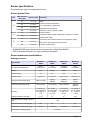
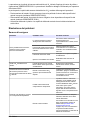
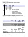
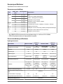
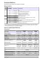
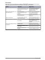
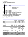
Sensor specifications
Specifications are subject to change without notice.
Sensor product line
Gas
Max. Pressure
rating (bar)
Sensor models Comments
O
2
20 31 11x.yz
Where :
x=Sensor special characteristics
(0 or 1; depending on application)
y=Membrane O-ring material
(0=EDPM; 1=Viton; 2=Kalrez; 4=Nitril)
z=Head material
(1=Stainless Steel; 2=Peek; 4=Hastelloy; 5=Titanium; 7= Monel)
Suffixes (when used):
A denotes a sensor with fast response to temperature change
E denotes an EEx certified sensor (Ex-Proof)
s denotes a Smart sensor
50 31 12x.yz
100 31 13x.yz
200 31 14x.yz
O
3
20 31 31x.yz
100 31 33x.yz
H
2
50 31 21x.yz
100 31 23x.yz
200 31 24x.yz
• All ORBISPHERE electrochemical sensor enclosures are certified IP68 / NEMA4
• PEEK (Polyetheretherketone) is a highly crystalline thermoplastic
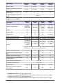
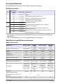
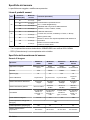
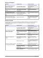
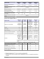
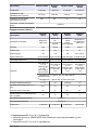
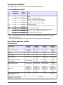
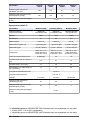
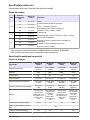
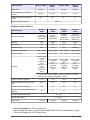
Sensor membrane specifications
Hydrogen sensors
Specification
Membrane
2956A
Membrane
2952A
Membrane
2995A
Membrane
29015A
Recommended applications
Trace
measurement
Low
concentration
Average
concentration
High
concentration
Material PFA Tefzel
®
Tedlar
®
Saran
Thickness [μm] 25 25 12.5 23
Calibration gas 1% pure H
2
10% pure H
2
100% pure H
2
100% pure H
2
Dissolved measurement range 0 ppb to 75 ppb
0 ppb to
300 ppb
0 ppb to
3200 ppb
0 ppb to
32 ppm
Gaseous measurement range 0 Pa to 5 kPa 0 Pa to 20 kPa 0 Pa to 200 kPa
0 kPa to
2000 kPa
Accuracy
The greater of
±1% of reading or
± 0.03 ppb, or ±
1 Pa
The greater of
±1% of reading
or ± 0.09 ppb,
or ± 6 Pa
The greater of
±1% of reading or
± 1 ppb, or ±
50 Pa
The greater of
±1% of reading
or ± 10 ppb, or
± 1 kPa
Integrated radiation dose limit 2 x 10
4
10
8
10
8
N/A
Expected current in air @ 1 bar 25°C
[μA]
N/A
Expected current in pure gas [μA] 150 50 5 0.5
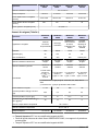
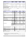
Temperature compensation range 0 to 50°C 0 to 50°C 10 to 45°C 10 to 45 °C
Temperature measuring range -5 to 100° C
English 3

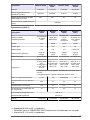
Specification
Membrane
2956A
Membrane
2952A
Membrane
2995A
Membrane
29015A
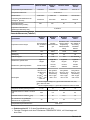
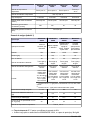
Response time
1
2 seconds 5 seconds 6 seconds 50 seconds
Recommended minimum liquid flow
rate
2
[mL/min]
50 to 220 40 to 200 20 to 70 20 to 40
Recommended minimum linear flow
rate
2
[cm/sec]
200 150 50 30
Recommended gaseous flow rate
[L/min]
0.005 to 3
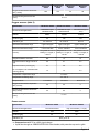
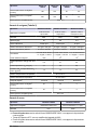
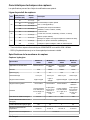
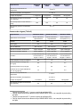
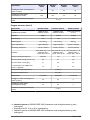
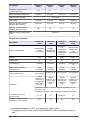
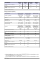
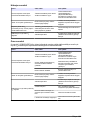
Oxygen sensors (table 1)
Specification
Membrane
2956A
Membrane
2958A
Membrane
29552A
Membrane
2952A
Recommended applications
Corrosion
control, De-
aerated water
Beverage, Lab.
applications
In line wort,
Air/O
2
injection,
Sewage
treatment
Corrosion
control, In line
beverage, De-
aerated water
Material PFA Tefzel
®
PTFE Tefzel
®
Thickness [μm] 25 12.5 50 25
Calibration gas Air Air Air Air / pure O
2
Dissolved measurement range 0 ppb to 20 ppm 0 ppb to 40 ppm 0 ppb to 80 ppm 0 ppb to 80 ppm
Gaseous measurement range 0 Pa to 50 kPa 0 Pa to 100 kPa 0 Pa to 200 kPa 0 Pa to 200 kPa
Accuracy
The greater of
±1% of reading
or ± 0.1 ppb
(1)
,
or ± 1 ppb
(2)
, or
± 0.25 Pa
The greater of
±1% of reading
or ± 1 ppb, or ±
2 Pa
The greater of
±1% of reading
or ± 2 ppb, or ±
5 Pa
The greater of
±1% of reading
or ± 2 ppb, or ±
5 Pa
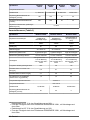
(1)
Accuracy is ± 0.1 ppb for 410, 510, 362x, 360x and 3655 instruments
(2)
Accuracy is ± 1 ppb for 366x and 3650 instruments
Integrated radiation dose limit 2 x 10
4
10
8
N/A 10
8
Expected current in air @ 1 bar 25°C
[μA]
26.4 9.4 6.3 5.4
Expected current in pure O
2
[μA] 132 47 31.4 27
O
2
consumption in O
2
saturated water
at 25°C [μg/hour]
40 14 9.4 8
Temperature compensation range -5 to 60°C
Temperature measuring range -5 to 100° C
Response time
3
7.2 seconds 9.5 seconds 90 seconds 38 seconds
Recommended minimum liquid flow
rate
4
[mL/min]
180 120 50 50
1
Response time at 25°C for a 90% signal change
2
Liquid flow through an ORBISPHERE 32001 flow chamber, with protection cap and no grille
3
Response time at 25°C for a 90% signal change
4
Liquid flow through an ORBISPHERE 32001 flow chamber, with protection cap and no grille
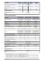
4 English

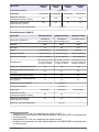
Specification
Membrane
2956A
Membrane
2958A
Membrane
29552A
Membrane
2952A
Recommended minimum linear flow
rate
4
[cm/sec]
200 100 30 30
Recommended gaseous flow rate
[L/min]
0.1 to 3
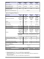
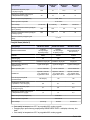
Oxygen sensors (table 2)
Specification Membrane 2935A Membrane 29521A Membrane 2995A
Recommended applications
Saturated to super
saturated levels
Saturated to super
saturated levels
In line hot wort (up to
70°C)
Material Halar
®
Tefzel
®
Tedlar
®
Thickness [μm] 25 125 12.5
Calibration gas Air / Pure O
2
Air / Pure O
2
Pure O
2
Dissolved measurement range 0 ppb to 400 ppm 0 ppb to 400 ppm 0 ppb to 2000 ppm
Gaseous measurement range 0 Pa to 1000 kPa 0 Pa to 1000 kPa 0 Pa to 5000 kPa
Accuracy
The greater of ±1% of
reading or ± 10 ppb, or
± 20 Pa
The greater of ±1% of
reading or ± 10 ppb, or
± 20 Pa
The greater of ±1% of
reading or ± 50 ppb, or
± 100 Pa
Integrated radiation dose limit N/A 10
8
10
8
Expected current in air @ 1 bar 25°C
[μA]
0.9 0.7 0.2
Expected current in pure O
2
[μA] 4.7 3.8 0.9
O
2
consumption in O
2
saturated water
at 25°C [μg/hour]
1.4 1.3 0.3
Temperature compensation range -5 to 60°C
Temperature measuring range -5 to 100° C
Response time
5
2.5 minutes 18 minutes 80 seconds
Recommended minimum liquid flow
rate
6
[mL/min]
25 25 5
Recommended minimum linear flow
rate
6
[cm/sec]
20 60 5
Recommended gaseous flow rate
[L/min]
0.1 to 3
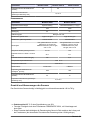
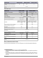
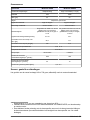
Ozone sensors
Specification Membrane 2956A Membrane 29552A
Recommended applications Trace measurement High concentration (> 1 mg/L)
Material PFA PTFE
Thickness [μm] 25 50
Calibration gas Span gas or air
5
Response time at 25°C for a 90% signal change
6
Liquid flow through an ORBISPHERE 32001 flow chamber, with protection cap and no grille
English 5

Specification Membrane 2956A Membrane 29552A
Dissolved measurement range 0 ppb to 50 ppm 0 ppb to 200 ppm
Gaseous measurement range 0 Pa to 10 kPa 0 Pa to 40 kPa
Accuracy
The greater of ±1% of reading (±
5% for sensors calibrated in air) or
± 5 ppb, or ±1 Pa
The greater of ±1% of reading (±
5% for sensors calibrated in air) or
± 20 ppb, or ± 4 Pa
Integrated radiation dose limit 2 x 10
4
N/A
Expected current in air @ 1 bar 25°C
[μA]
26.4 6.5
Expected current in pure gas [μA] 105 31.4
Temperature compensation range -5 to 45°C
Temperature measuring range -5 to 100° C
Response time
7
30 seconds 6 minutes
Recommended minimum liquid flow
rate
8
[mL/min]
350
9
100
9
Recommended minimum linear flow
rate
8
[cm/sec]
30 10
Recommended gaseous flow rate
[L/min]
0.01 to 3
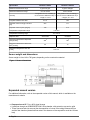
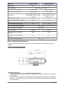
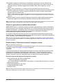
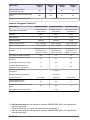
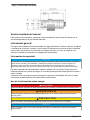
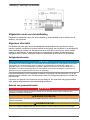
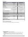
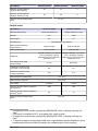
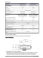
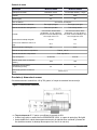
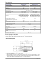
Sensor weight and dimensions
Sensor weight is from 140 to 700 grams, depending on the construction material.
Figure 1 Sensor dimensions
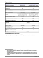
Expanded manual version
For additional information, refer to the expanded version of this manual, which is available on the
manufacturer's website.
7
Response time at 25°C for a 90% signal change
8
Liquid flow through an ORBISPHERE 32001 flow chamber, with protection cap and no grille
9
These flow rates take into account the decomposition of ozone in the tubing between the line
and the flow chamber (theoretical flow rates in the absence of decomposition would be 10 times
less)
6 English

General information
In no event will the manufacturer be liable for direct, indirect, special, incidental or consequential
damages resulting from any defect or omission in this manual. The manufacturer reserves the right to
make changes in this manual and the products it describes at any time, without notice or obligation.
Revised editions are found on the manufacturer’s website.
Safety information
N O T I C E
The manufacturer is not responsible for any damages due to misapplication or misuse of this product including,
without limitation, direct, incidental and consequential damages, and disclaims such damages to the full extent
permitted under applicable law. The user is solely responsible to identify critical application risks and install
appropriate mechanisms to protect processes during a possible equipment malfunction.
Please read this entire manual before unpacking, setting up or operating this equipment. Pay
attention to all danger and caution statements. Failure to do so could result in serious injury to the
operator or damage to the equipment.
Make sure that the protection provided by this equipment is not impaired. Do not use or install this
equipment in any manner other than that specified in this manual.
Use of hazard information
D A N G E R
Indicates a potentially or imminently hazardous situation which, if not avoided, will result in death or serious injury.
W A R N I N G
Indicates a potentially or imminently hazardous situation which, if not avoided, could result in death or serious
injury.
C A U T I O N
Indicates a potentially hazardous situation that may result in minor or moderate injury.
N O T I C E
Indicates a situation which, if not avoided, may cause damage to the instrument. Information that requires special
emphasis.
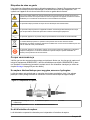
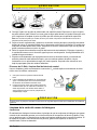
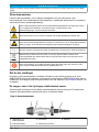
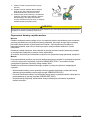
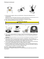
Precautionary labels
Read all labels and tags attached to the instrument. Personal injury or damage to the instrument
could occur if not observed. A symbol on the instrument is referenced in the manual with a
precautionary statement.
This is the safety alert symbol. Obey all safety messages that follow this symbol to avoid potential
injury. If on the instrument, refer to the instruction manual for operation or safety information.
This symbol indicates that a risk of electrical shock and/or electrocution exists.
This symbol indicates the presence of devices sensitive to Electro-static Discharge (ESD) and
indicates that care must be taken to prevent damage with the equipment.
This symbol, when noted on a product, indicates the instrument is connected to alternate current.
English 7

Electrical equipment marked with this symbol may not be disposed of in European domestic or
public disposal systems. Return old or end-of-life equipment to the manufacturer for disposal at no
charge to the user.
Products marked with this symbol indicates that the product contains toxic or hazardous substances
or elements. The number inside the symbol indicates the environmental protection use period in
years.
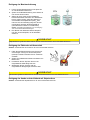
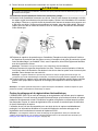
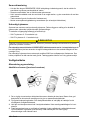
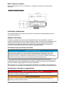
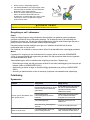
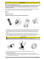
What you have received
Check that all mounting hardware is included. Note that, unless the sensor is part of ORBISPHERE
equipment that includes it, the sensor must be installed in an ORBISPHERE socket or flow chamber
that allows contact with the sample flow to be analyzed (refer to Installation on page 8 for details).
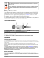
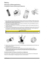
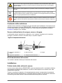
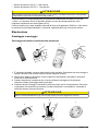
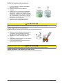
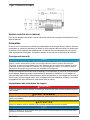
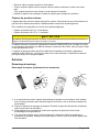
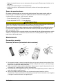
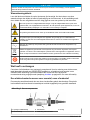
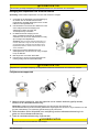
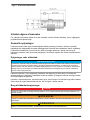
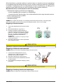
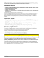
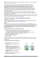
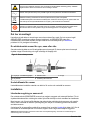
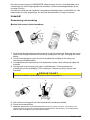
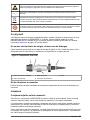
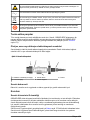
An oxygen, ozone, or hydrogen electrochemical sensor
The sensor head is protected by a screw-on plastic storage cap. A plastic screw-on base protects the
connection socket, and provides at the same time a suitable stand.
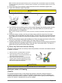
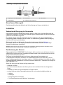
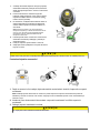
Figure 2 Sensor components
1 Storage and calibration cap 3 Sensor base 5 Collar
2 Protection cap 4 Connection to instrument
A sensor maintenance kit
The maintenance kit includes the material needed to service and maintain the sensor.
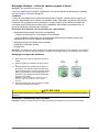
Installation
Initial sensor cell cleaning
Your ORBISPHERE electrochemical sensor has been thoroughly cleaned and tested at the factory.
To protect the electrodes from oxidation, the cell has been filled with electrolyte and a membrane has
been installed.
However, shipping and storage conditions can adversely affect electrochemical sensor cells,
therefore a sensor service (cell cleaning & membrane replacement) must be performed before using
the sensor.
To perform a sensor service, see the instructions in the section entitled Maintenance on page 10. If
you are not familiar with sensor servicing, your Hach Lange representative will be glad to assist you.
Note: Electrochemical H
2
sensors do not require a complete cleaning procedure, as dechloridization and
rechloridization processes are normally not required.
Sensor positioning
Unless the sensor is part of the ORBISPHERE equipment that includes it, the sensor must be
installed in an ORBISPHERE socket or flow chamber, that allows the contact with the sample fluid to
be analyzed.
8
English

The sensor and measuring instrument are connected by a cable and two 10 pin connectors. The
standard sensor cable length is 3 meters, but extension cables of up to 1,000 meters are available,
still retaining the same signal sensitivity. If the model 28117 pressure sensor is used, the maximum
cable length is 50 meters.
Ensure that the sensor will be mounted:
• perpendicular to the pipe
• on a horizontal pipe section (or on flow-ascending vertical pipe)
• minimum of 15 meters away from the pump's discharge side
• in a place where the sample flow is stable and rapid, and as far as possible from:
• valves
• pipe bends
• the suction side of any pumps
• a CO
2
injection system or similar
Note: There may be situations where not all the above conditions can be met. If this is the case, or you have any
concerns, please consult your Hach Lange representative to appraise the situation and define the best applicable
solution.
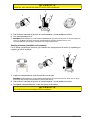
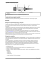
Sensor insertion
• Insert the sensor straight into the flow chamber or socket. Do not twist the sensor.
• Hand tighten the attaching collar.
• Connect the sensor cable.
• Check for leaks; replace O-rings if product leaks are visible.
Instructions for micro volume flow chambers
Do not twist the sensor when inserting it into a micro volume flow chamber. This rotation may twist
the protection cap, thus changing the membrane position. This can modify the membrane measuring
conditions, and affect measurement precision.
Sensor removal
• If not using the ORBISPHERE 32003 insertion/extraction valve you will need to shut off the sample
flow and drain the sampling circuit of liquid.
• Remove the sensor cable connected at the sensor end.
• Hold the sensor body in one hand to avoid rotation, and unscrew the collar with the other hand.
• Pull the sensor straight out of the socket or flow chamber.
• Install the sensor storage cap and sensor base (to protect the connection).
External pressure sensor
The system can be fitted with an external pressure sensor. This enables a measure of fraction of gas
under variable pressure conditions during gas phase measurement.
Two models are available, depending on applied pressure:
• 28117 Pressure sensor 0 - 5 bar absolute
• 28117C Pressure sensor 0 - 1 bar absolute
C A U T I O N
Do NOT exceed the pressure range of the sensor. This would permanently deform the sensor membrane, thus
delivering incorrect pressure values in the future.
The external sensor connects to the ORBISPHERE measuring equipment with a 1 meter cable and a
4 pin connector (an optional extension cable can be used, but total length should not exceed
50 meters).
English
9

The external pressure sensor can be installed in the model 32002.xxx multi parameter flow chamber.
It is held in place by a blue threaded collar. Tightness is assured by the O-ring on the sensor seat.
Maintenance
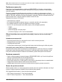
Disassembly and assembly
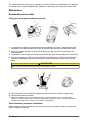
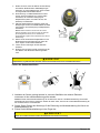
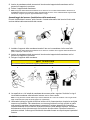
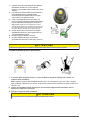
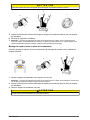
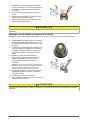
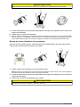
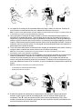
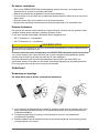
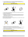
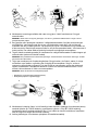
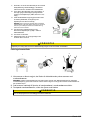
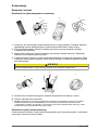
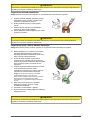
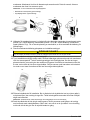
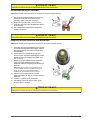
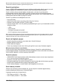
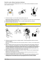
Taking the sensor apart (membrane removal)
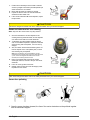
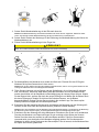
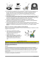
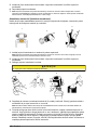
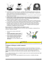
1. 2. 3. 4.
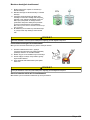
1. It is important to install the electrochemical sensor standing on its base. This base offers good
protection for the delicate connector socket, at the same time providing a suitable work stand.
2. Remove the plastic storage cap. Unscrew the protection cap, using the tool provided in the
maintenance kit.
3. Pay attention to the components inside the protection cap. Note the assembly order of each item.
4. Pull up the attaching ring with the tool provided in the maintenance kit. Remove the membrane
and mask (if applicable). Drain the electrolyte into a sink and rinse the sensor cavity with tap
water.
C A U T I O N
Avoid eye or skin contact with electrolyte which can be slightly corrosive.
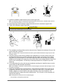
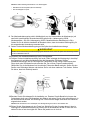
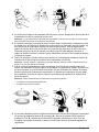
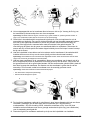
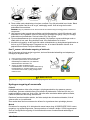
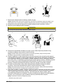
5.
6.
7.
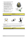
5. Insert the prongs of the membrane support removal tool into the membrane support holes.
6. Unscrew the membrane support.
7.
Note: The membrane support is individually machined and paired with the sensor. For correct sensor
operation, it is ESSENTIAL to keep a membrane support with its respective sensor. Should the membrane
support require replacement, contact your Hach Lange representative.
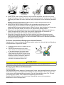
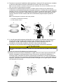
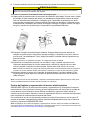
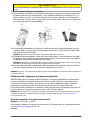
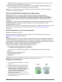
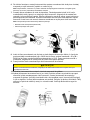
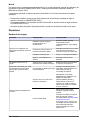
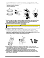
Sensor assembly (membrane installation)
Before starting the sensor reassembly, proceed to the sensor maintenance section for anode and
cathode cleaning instructions.
10
English

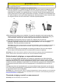
1.
2.
3.
1. Install the membrane support with the groove on the upper side.
Note: The membrane support is individually machined and paired with the sensor. Therefore make sure that
the correct membrane support is used on the correct sensor.
2. Insert the prongs of the membrane support removal tool into the membrane support holes.
3. Tighten the membrane support finger tight.
C A U T I O N
Too much torque will damage the sensor electrodes.
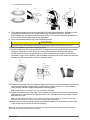
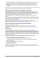
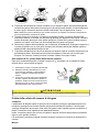
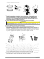
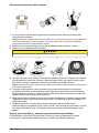
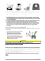
4. 5. 6. 7.
4. The membrane mounting surface must be clean and even. Replace the membrane O-ring on the
sensor head with a new one.
Note: The 29039.4 Nitril O-ring can be reused if it is still in good condition. Membrane O-rings are part of the
protection cap kit.
5. Using the syringe or bottle nozzle included in the maintenance kit, fill up the sensor cavity with
electrolyte. Be careful not to touch the electrodes with the needle, as a scratch on the surface
may lead to loss of performance. Tilt the sensor slightly and inject into the lower hole, pushing
bubbles out at the upper hole. Gently tap on the sensor side to move trapped bubbles. Return the
sensor to the vertical position. The last drop of electrolyte should form a cupola on top of the
sensor tip.
6. In the maintenance kit, pick up the two part membrane mounting tool. Install the sleeve over the
sensor head (end with shoulder downwards).
Note: Once installed, a membrane cannot be reused. Avoid touching the membrane with bare fingers, as this
may affect its sensitivity.
7. Take a few membranes out of the storage box. Using tweezers included in the kit, pick up one
membrane of the stack, and gently place it on the sensor tip. Make sure it is centered, and no
bubble is trapped. If a sensor mask is used, place it directly on top of the membrane. The
membrane diameter is larger than sensor head diameter. This is normal, as the membrane will
fold over the sensor tip.
Note: Distinguish the membrane from the protection paper:
• The membrane is transparent (translucent).
English
11

• The protection paper is opaque.
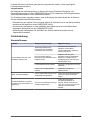
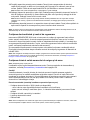
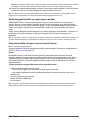
8. 9. 10. 11.
8. The membrane holding ring comes in two slightly different internal diameters, depending on the
membrane(s) total thickness (A = 29228 holding ring, membrane thickness < 50μ; B =
29229 holding ring, membrane(s) total thickness ≥ 50μ). For a correct membrane installation, be
sure to use the correct holding ring for the application.
9. Place the membrane holding ring on the installation tool tip.
C A U T I O N
To avoid damaging the membrane, make sure that the tool tip is totally clean and its surface is even.
10. Insert the installation tool inside the guiding sleeve.
11. Push the installation tool firmly downwards. This clasps the mounting ring onto the sensor head,
folding the membrane over the sensor tip. Remove the installation tool and guiding sleeve.
Visually check for correct ring placement, try to push it down with your fingers. Check that the
membrane is tight, with no wrinkles, and no bubbles are present. Rinse the sensor with tap water
and wipe dry with a clean cloth. Check for electrolyte leaks.
12.
13.
14.
12. Prepare the protection cap for installation. Replace all the parts inside the protection cap with new
ones (except the grille), and place them in the order they were removed. The Tefzel washers,
under the cap, should be slightly lubricated with silicone grease.
Note: The illustration is an example only. Your configuration may differ.
13. Tighten the protection cap finger tight. Then, complete the process using the tool provided in the
maintenance kit. Insert into each of the four holes in turn, and tighten as far as possible. Tighten
each hole only once.
Note: The grille inside the protection cap should be free to move during tightening. Therefore, and to avoid
damage to the membrane, do not touch the grille during the tightening process.
14. Always store the sensor with the storage cap and base installed. Put a few drops of clean water
in the storage cap to prevent the sensor cell drying.
Note: A sensor that has been taken apart or serviced must always be calibrated. Allow the sensor to settle for
30 minutes, before performing the sensor calibration.
12
English

Electrochemical cleaning and regeneration center
The ORBISPHERE 32301 is a very efficient cleaning and regeneration tool for electrochemical
sensors. This tool reverses the electrochemical process that is taking place in the sensor cell during
normal operation. This removes oxidation and at the same time regenerates the surface of the
electrodes. In addition, the regeneration center offers a continuity tester for checking the sensor
electronics.
Use of this tool is recommended for a noticeably extended sensor life. Detailed information on how to
use the cleaning and regeneration center is included in the 32301 Operator Manual.
Note: It is mandatory to use the 32301 Sensor Cleaning and Regeneration Center for servicing electrochemical H
2
sensors. This process is called dechloridization and rechloridization of the electrodes (see Hydrogen sensor cell
cleaning on page 15).
Chemical cleaning: oxygen and ozone sensor cell
Note: Not applicable for H
2
sensors.
The following supposes that the sensor has been taken apart. For disassembly and assembly
procedures, see Disassembly and assembly on page 10.
Conditions
Wear on the membrane, and chemical reactions within the sensor, requires that the sensor be
serviced regularly to restore its original sensitivity. Service includes electrode cleaning and
membrane replacement. A clear sign that a sensor maintenance is required is when measurements
are noticeably less stable than usual, and when a calibration does not improve the situation.
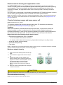
Method description (see following step-by-step procedure)
• Electrochemical cleaning with 32301 (if available)
… when not available or results are insufficient.
... for sensors used in harsh environments (e.g., hydrocarbon industry) or very dirty sensors.
• Anode and cathode chemical cleaning
• Central electrode polishing
• Final rinsing
Note: To eliminate any silver residue that ammonia cleaning cannot remove, it is sometimes required to repeat the
chemical cleaning using nitric acid (HNO
3
, not over 70% by weight).
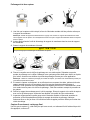
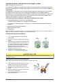
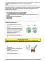
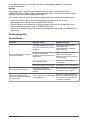
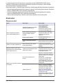
Membrane support cleaning
1. Empty and rinse the electrolyte reservoir under tap
water.
2. Rinse membrane support under water and wipe it
dry.
3. Check for the presence of any residue on the
surfaces. Residue can be removed by placing the
support in a container of nitric acid (HNO
3
, not over
70% by weight) until it recovers its original
appearance (normally within 30 seconds).
Note: Only use nitric acid to clean very dirty membrane
support.
4. Rinse one minute under tap water and check again
for surface cleanliness.
C A U T I O N
Nitric acid is dangerous! Please refer to the safety information from your chemical supplier.
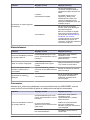
Electrodes ammonia cleaning
Note: Only use ammonia to clean very dirty sensors.
English
13

1. Fill the sensor electrolyte reservoir with a solution
of 25% by weight ammonium hydroxide (NH
4
OH) in
water and leave for 10 minutes.
2. Rinse with tap water for at least one minute.
3. Inspect the sensor head. The counter electrode
should be a silver-white color.
4. If the counter electrode still shows deposits, repeat
the procedure.
C A U T I O N
Ammonia is dangerous! Please refer to the safety information from your chemical supplier.
Anode and cathode nitric acid cleaning
Note: Only use nitric acid to clean very dirty sensors.
1. Check for the absence of silver deposit on the
central guard ring electrode walls, as such deposits
can make contact with the counter electrode.
2. To eliminate any silver residue inside the sensor
cell, it is sometimes required to repeat the chemical
cleaning using nitric acid (HNO
3
, not over 70% by
weight).
3. Also, the 32301 electrochemical cleaning does not
remove deposit on the cell’s plastic parts, so nitric
acid cleaning may be required.
Note: This procedure is not recommended for normal
maintenance, and should not be used more often than twice
a year, as the acid degrades the metal of the counter
electrode, thus reducing the sensor's life.
4. Place concentrated nitric acid into the sensor
electrolyte reservoir, and add 1 drop on the center
electrode.
5. Leave for no longer than 3 seconds.
6. Quickly empty the acid and rinse thoroughly under
tap water for one minute.
C A U T I O N
Nitric acid is dangerous! Please refer to the safety information from your chemical supplier.
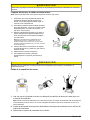
Sensor face polishing
1.
2.
3.
1. Once the sensor has been cleaned, the face of the center electrode must be polished together
with the membrane support.
14
English

Note: Install the membrane support with the groove on the upper side. The membrane support is individually
machined and paired with the sensor. Therefore make sure that the correct membrane support is used on the
correct sensor.
2. Insert the prongs of the membrane support removal tool into the membrane support holes.
3. Tighten the membrane support finger tight.
C A U T I O N
Too much torque will damage the sensor electrodes.
4. 5. 6. 7.
4. Place the dish with the polishing cloth on a flat surface. Spread a little polishing powder onto the
cloth. Mix with a few drops of water to get a grey, milky liquid. Make sure to use the correct
polishing powder for your application.
Note: Use one polishing cloth per sensor model, to prevent a possible contamination through metal particle
transfer.
5. Holding the sensor vertically, and using a circular motion, polish the sensor face for at least
30 seconds, until the electrodes are clean and shiny. This step may need to be repeated several
times. Make sure to avoid skin contact with the polishing cloth; it should be kept free of dust and
grease.
6. Remove the membrane support with installation tool. Rinse the support and sensor cavity with a
strong jet of clean water. Use distilled water if the water quality is doubtful.
7. Carefully inspect that the tiny groove between the center electrode and the guard ring electrode is
totally clean and free of polishing residue. Clean only with a strong water spray. The edge of a
paper sheet can be used to remove sticking residue.
O
3
Sensor only: final center electrode cleaning
Once the O
3
sensor has been successfully cleaned and polished, a final nitric acid treatment should
be applied, as follows:
1. Place the sensor in a vertical position on its base.
2. Fill the electrolyte reservoir with a few drops of
water, just enough to cover the outer electrode. The
center electrode must be kept dry.
3. Place a drop of nitric acid on the center electrode,
covering only the electrode and guard ring. Avoid
spilling acid into the water. Wait less than a minute,
then rinse thoroughly under tap water.
C A U T I O N
Nitric acid is dangerous! Please refer to the safety information from your chemical supplier.
Hydrogen sensor cell cleaning
Conditions
The hydrogen analyzer works on the principle that hydrogen molecules, passing through the
membrane, generate an electric current at the platinum anode surface. For this to take place, an
extremely clean metal surface is essential. If any film, grease or other impurity covers the platinum
surface, the reaction is impeded and may even be stopped.
English
15

In addition, the chemical reaction that takes place on the chloridized silver cathode leads to loss of
performance after a certain operation time.
As a result, a sensor service must be carried out to restore its original performance.
Method
The procedure for cleaning the H
2
electrochemical sensor requires the use of the ORBISPHERE
32301 Sensor Cleaning and Regeneration Center. This procedure is explained in detail in the
32301 Operator's Manual.
As an overview, H
2
electrochemical sensor cleaning consists of the following sequence of operations:
• Dechloridization of the cathode: This process removes the chloride film from the silver cathode
surface (carried out by the ORBISPHERE 32301).
• Rechloridization of the cathode: A layer of silver chloride is grown on the cathode's surface
(carried out by the ORBISPHERE 32301).
• Activation of the platinum anode: The center anode surface is polished, and treated with nitric acid.
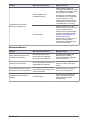
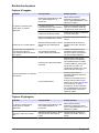
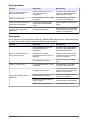
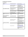
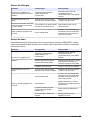
Troubleshooting
Oxygen sensor
Problem Probable cause Possible solution
Sensor won't calibrate, even after
thorough servicing.
Repeated calibrations go beyond
"expected limits" of instrument.
MOCA 3600 only: Select membrane
from "Options/Membrane" menu.
Then, calibrate the sensor.
Instrument internal barometric
pressure sensor needs calibration.
Calibrate internal barometer against
a certified barometer. Do not correct
for sea level !
Wet membrane interface.
Wipe dry with a tissue and re-
calibrate.
"H
2
S insensitivity" option enabled.
Disable on the measuring
instrument.
"0000" O
2
levels displayed.
Wrong reading scale "XXXX"
selected for display unit.
Change reading scale by selecting
"X.XXX, XX.XX or XXX.X".
Shorter than expected sensor
operation in relatively high dissolved
O
2
concentration.
High O
2
concentrations generate
deposits more quickly.
Install a less permeable membrane.
Turn off the analyzer when sensor is
not in a low O
2
concentration.
Unexpected or inaccurate dissolved
O
2
readings.
Air leak on product sample line.
Set flow rate to 100 mL/min. Wait
until stable, then slowly double this
flow rate.
The stable value of dissolved O
2
reading must be the same as
before. A variation related to flow
rate is a clear sign of an air leak in
the line.
High residual current.
Place sensor in de-aerated sample;
wait for low reading:
Check concentration against low
measurement limit (see tables in
Sensor membrane specifications
on page 3). If concentration is
significantly higher than low limit, try
a sensor service.
16 English

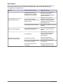
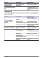
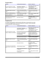
Hydrogen sensor
Problem Probable cause Possible solution
Sensor won't calibrate, even after
thorough servicing.
Repeated calibrations go beyond
"expected limits" of instrument.
MOCA 3600 only: Select membrane
from "Options/Membrane" menu.
Then, calibrate the sensor.
"0000" H
2
levels displayed.
Wrong reading scale "XXXX"
selected for display unit.
Change reading scale by selecting
"X.XXX, XX.XX or XXX.X".
Shorter than expected sensor
operation in relatively high H
2
concentration.
High H
2
concentrations require
more work from electrochemical
sensor.
Shut off analyzer when not needed.
Unexpected or inaccurate H
2
readings.
High residual current.
If concentration is significantly
higher than low limit, try a sensor
service.
Ozone sensor
When the O
3
sensor has been properly calibrated using the ORBISPHERE measuring instrument,
the sensor has to settle down for up to 24 hours when used in very low O
3
concentration conditions.
Problem Probable cause Possible solution
Sensor won't calibrate, even after
thorough servicing.
Repeated calibrations go beyond
"expected limits" of instrument.
MOCA 3600 only: Select membrane
from "Options/Membrane" menu.
Then, calibrate the sensor.
Instrument internal barometric
pressure sensor needs calibration.
Calibrate internal barometer against
a certified barometer. Do not correct
for sea level !
Wet membrane interface.
Wipe dry with a tissue and re-
calibrate.
"0000" O
3
levels displayed.
Wrong reading scale "XXXX"
selected for display unit.
Change reading scale by selecting
"X.XXX, XX.XX or XXX.X".
Unexpected or inaccurate dissolved
O
3
readings.
High residual current.
If concentration is significantly
higher than low limit, try a sensor
service.
Insufficient flow rate.
Regulate flow equivalent to
membrane specified levels.
Length of sample line allows O
3
time to react.
Reduce length of sample tubing.
Doesn't match lab samples.
Take samples at close proximity to
sensor.
English 17

Sensorspezifikationen
Die Spezifikationen können ohne Vorankündigung Änderungen unterliegen.
Produktlinie Sensor
Gas
Max. Druck
Belastbarkeit
(bar)
Sensormodelle Kommentare
O
2
20 31 11x.yz wobei:
x=spezielle Eigenschaften des Sensors
(0 oder 1; in Abhängigkeit von der Anwendung)
y=Material des O-Rings der Membran
(0=EDPM; 1=Viton; 2=Kalrez; 4=Nitril)
z=Material des Kopfes
(1=St Stahl; 2=Peek; 4=Hastelloy; 5=Titan; 7= Monel)
Suffixe (wenn verwendet):
A bezeichnet einen Sensor mit schneller Reaktion auf
Temperaturänderungen
E bezeichnet einen Sensor mit EEx-Zertifizierung (Ex-Proof)
s Bezeichnet einen Smart-Sensor
50 31 12x.yz
100 31 13x.yz
200 31 14x.yz
O
3
20 31 31x.yz
100 31 33x.yz
H
2
50 31 21x.yz
100 31 23x.yz
200 31 24x.yz
• Alle Gehäuse der elektrochemischen ORBISPHERE-Sensoren verfügen über die Zertifizierung
IP68 / NEMA4
• PEEK (Polyetheretherketon) ist ein hochgradig kristallisiertes Thermoplast
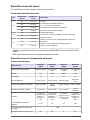
Spezifikationen der Membran des Sensors
Wasserstoffsensoren
Spezifikation Membran 2956A
Membran
2952A
Membran 2995A
Membran
29015A
Empfohlene Anwendungen Spurenmessung
Niedrige
Konzentration
Durchschnittliche
Konzentration
Hohe
Konzentration
Material PFA Tefzel
®
Tedlar
®
Saran
Stärke [μm] 25 25 12,5 23
Kalibrierungsgas 1% reiner H
2
10% reiner H
2
100% reiner H
2
100% reiner H
2
Messbereich gelöste Gase 0 ppb bis 75 ppb
0 ppb bis
300 ppb
0 ppb bis
3200 ppb
0 ppb bis
32 ppm
Messbereich gasförmige Medien 0 Pa bis 5 kPa 0 Pa bis 20 kPa 0 Pa bis 200 kPa
0 kPa bis
2000 kPa
Genauigkeit
Das größere
Wert von ±1%
der Messung
oder ± 0,03 ppb,
oder ± 1 Pa
Das größere
Wert von ±1%
der Messung
oder ±
0,09 ppb, oder
± 6 Pa
Das größere
Wert von ±1%
der Messung
oder ±1 ppb, oder
± 50 Pa
Das größere
Wert von ±1%
der Messung
oder ±10 ppb,
oder ± 1 kPa
Integrierter
Strahlungsdosisgrenzwert
2 x 10
4
10
8
10
8
N/A
Erwarteter Strom in Luft bei 1 bar
25°C [µA]
N/A
Erwarteter Strom in reinem Gas [µA] 150 50 5 0,5
18 Deutsch

Spezifikation Membran 2956A
Membran
2952A
Membran 2995A
Membran
29015A
Temperaturkompensationsbereich 0 bis 50°C 0 bis 50°C 10 bis 45 °C 10 bis 45 °C
Temperaturmessbereich -5 bis 100 °C
Reaktionszeit
1
2 Sekunden 5 Sekunden 6 Sekunden 50 Sekunden
Empfohlene Mindestflussrate der
Flüssigkeit
2
[mL/min]
50 bis 220 40 bis 200 20 bis 70 20 bis 40
Empfohlene lineare
Mindestflussrate
2
[cm/Sek.]
200 150 50 30
Empfohlene Flussrate des
gasförmigen Mediums [L/min]
0,005 bis 3
Sauerstoffsensoren (Tabelle 1)
Spezifikation
Membran
2956A
Membran
2958A
Membran
29552A
Membran
2952A
Empfohlene Anwendungen
Korrosionskontr
olle, entlüftetes
Wasser
Getränk,
Laboranwendun
gen
Bierwürze in der
Leitung Luft/O
2
-
Einspritzung,
Abwasseraufber
eitung
Korrosionskontr
olle, Getränk in
der Leitung,
entlüftetes
Wasser
Material PFA Tefzel
®
PTFE Tefzel
®
Stärke [μm] 25 12,5 50 25
Kalibrierungsgas Luft Luft Luft Air / reines O
2
Messbereich gelöste Gase
0 ppb bis
20 ppm
0 ppb bis
40 ppm
0 ppb bis
80 ppm
0 ppb bis
80 ppm
Messbereich gasförmige Medien 0 Pa bis 50 kPa
0 Pa bis
100 kPa
0 Pa bis
200 kPa
0 Pa bis
200 kPa
Genauigkeit
Das größere
Wert von ±1%
der Messung
oder ±
0,1 ppb
(1)
, oder
± 1 ppb
(2)
, oder
± 0,25 Pa
Das größere
Wert von ±1%
der Messung
oder ±1 ppb,
oder ± 2 Pa
Das größere
Wert von ±2%
der Messung
oder ±1 ppb,
oder ± 5 Pa
Das größere
Wert von ±2%
der Messung
oder ±1 ppb,
oder ± 5 Pa
(1)
Die Genauigkeit beträgt ± 0,1 ppb für die Instrumente 410, 510,
362x, 360x und 3655.
(2)
Die Genauigkeit beträgt ± 1 ppb für die Instrumente 366x und 3650.
Integrierter Strahlungsdosisgrenzwert 2 x 10
4
10
8
N/A 10
8
Erwarteter Strom in Luft bei 1 bar 25°C
[µA]
26,4 9,4 6,3 5,4
Erwarteter Strom in reinem O
2
[µA] 132 47 31,4 27
O
2
-Verbrauch in O
2
-gesättigtem
Wasser bei 25 °C [µg/Stunde]
40 14 9,4 8
Temperaturkompensationsbereich -5 bis 60 °C
1
Reaktionszeit bei 25 °C für eine Signaländerung von 90%
2
Fluss der Flüssigkeit durch eine Flusskammer ORBISPHERE 32001, mit Schutzkappe und
ohne Gitter
Deutsch 19

Spezifikation
Membran
2956A
Membran
2958A
Membran
29552A
Membran
2952A
Temperaturmessbereich -5 bis 100 °C
Reaktionszeit
3
7,2 Sekunden 9,5 Sekunden 90 Sekunden 38 Sekunden
Empfohlene Mindestflussrate der
Flüssigkeit
4
[mL/min]
180 120 50 50
Empfohlene lineare Mindestflussrate
4
[cm/Sek.]
200 100 30 30
Empfohlene Flussrate des gasförmigen
Mediums [L/min]
0,1 bis 3
Sauerstoffsensoren (Tabelle 2)
Spezifikation Membran 2935A Membran 29521A Membran 2995A
Empfohlene Anwendungen
Gesättigte bis
übersättigte Pegel
Gesättigte bis
übersättigte Pegel
Heiße Bierwürze in
der Leitung (bis zu
70°C)
Material Halar
®
Tefzel
®
Tedlar
®
Stärke [μm] 25 125 12,5
Kalibrierungsgas Air / reines O
2
Air / reines O
2
Reines O
2
Messbereich gelöste Gase 0 ppb bis 400 ppm 0 ppb bis 400 ppm 0 ppb bis 2.000 ppm
Messbereich gasförmige Medien 0 Pa bis 1000 kPa 0 Pa bis 1000 kPa 0 Pa bis 5.000 kPa
Genauigkeit
Das größere Wert von
±1% der Messung
oder ±10 ppb, oder ±
20 Pa
Das größere Wert von
±1% der Messung
oder ±10 ppb, oder ±
20 Pa
Das größere Wert von
±1% der Messung
oder ±50 ppb, oder ±
100 Pa
Integrierter Strahlungsdosisgrenzwert N/A 10
8
10
8
Erwarteter Strom in Luft bei 1 bar
25°C [µA]
0,9 0,7 0,2
Erwarteter Strom in reinem O
2
[µA] 4,7 3,8 0,9
O
2
-Verbrauch in O
2
-gesättigtem
Wasser bei 25 °C [µg/Stunde]
1,4 1,3 0,3
Temperaturkompensationsbereich -5 bis 60 °C
Temperaturmessbereich -5 bis 100 °C
Reaktionszeit
5
2,5 Minuten 18 Minuten 80 Sekunden
Empfohlene Mindestflussrate der
Flüssigkeit
6
[mL/min]
25 25 5
3
Reaktionszeit bei 25 °C für eine Signaländerung von 90%
4
Fluss der Flüssigkeit durch eine Flusskammer ORBISPHERE 32001, mit Schutzkappe und
ohne Gitter
5
Reaktionszeit bei 25 °C für eine Signaländerung von 90%
6
Fluss der Flüssigkeit durch eine Flusskammer ORBISPHERE 32001, mit Schutzkappe und
ohne Gitter
20 Deutsch
Strona się ładuje...
Strona się ładuje...
Strona się ładuje...
Strona się ładuje...
Strona się ładuje...
Strona się ładuje...
Strona się ładuje...
Strona się ładuje...
Strona się ładuje...
Strona się ładuje...
Strona się ładuje...
Strona się ładuje...
Strona się ładuje...
Strona się ładuje...
Strona się ładuje...
Strona się ładuje...
Strona się ładuje...
Strona się ładuje...
Strona się ładuje...
Strona się ładuje...
Strona się ładuje...
Strona się ładuje...
Strona się ładuje...
Strona się ładuje...
Strona się ładuje...
Strona się ładuje...
Strona się ładuje...
Strona się ładuje...
Strona się ładuje...
Strona się ładuje...
Strona się ładuje...
Strona się ładuje...
Strona się ładuje...
Strona się ładuje...
Strona się ładuje...
Strona się ładuje...
Strona się ładuje...
Strona się ładuje...
Strona się ładuje...
Strona się ładuje...
Strona się ładuje...
Strona się ładuje...
Strona się ładuje...
Strona się ładuje...
Strona się ładuje...
Strona się ładuje...
Strona się ładuje...
Strona się ładuje...
Strona się ładuje...
Strona się ładuje...
Strona się ładuje...
Strona się ładuje...
Strona się ładuje...
Strona się ładuje...
Strona się ładuje...
Strona się ładuje...
Strona się ładuje...
Strona się ładuje...
Strona się ładuje...
Strona się ładuje...
Strona się ładuje...
Strona się ładuje...
Strona się ładuje...
Strona się ładuje...
Strona się ładuje...
Strona się ładuje...
Strona się ładuje...
Strona się ładuje...
Strona się ładuje...
Strona się ładuje...
Strona się ładuje...
Strona się ładuje...
Strona się ładuje...
Strona się ładuje...
Strona się ładuje...
Strona się ładuje...
Strona się ładuje...
Strona się ładuje...
Strona się ładuje...
Strona się ładuje...
Strona się ładuje...
Strona się ładuje...
Strona się ładuje...
Strona się ładuje...
Strona się ładuje...
Strona się ładuje...
Strona się ładuje...
Strona się ładuje...
Strona się ładuje...
Strona się ładuje...
Strona się ładuje...
Strona się ładuje...
Strona się ładuje...
Strona się ładuje...
Strona się ładuje...
Strona się ładuje...
Strona się ładuje...
Strona się ładuje...
Strona się ładuje...
Strona się ładuje...
Strona się ładuje...
Strona się ładuje...
Strona się ładuje...
Strona się ładuje...
Strona się ładuje...
Strona się ładuje...
Strona się ładuje...
Strona się ładuje...
Strona się ładuje...
Strona się ładuje...
Strona się ładuje...
Strona się ładuje...
Strona się ładuje...
Strona się ładuje...
Strona się ładuje...
Strona się ładuje...
Strona się ładuje...
Strona się ładuje...
Strona się ładuje...
Strona się ładuje...
Strona się ładuje...
Strona się ładuje...
Strona się ładuje...
Strona się ładuje...
Strona się ładuje...
Strona się ładuje...
Strona się ładuje...
Strona się ładuje...
Strona się ładuje...
Strona się ładuje...
Strona się ładuje...
Strona się ładuje...
Strona się ładuje...
Strona się ładuje...
Strona się ładuje...
Strona się ładuje...
Strona się ładuje...
Strona się ładuje...
Strona się ładuje...
Strona się ładuje...
Strona się ładuje...
Strona się ładuje...
Strona się ładuje...
Strona się ładuje...
Strona się ładuje...
Strona się ładuje...
Strona się ładuje...
Strona się ładuje...
Strona się ładuje...
Strona się ładuje...
Strona się ładuje...
Strona się ładuje...
Strona się ładuje...
Strona się ładuje...
Strona się ładuje...
Strona się ładuje...
Strona się ładuje...
Strona się ładuje...
Strona się ładuje...
Strona się ładuje...
Strona się ładuje...
Strona się ładuje...
Strona się ładuje...
Strona się ładuje...
Strona się ładuje...
Strona się ładuje...
-
 1
1
-
 2
2
-
 3
3
-
 4
4
-
 5
5
-
 6
6
-
 7
7
-
 8
8
-
 9
9
-
 10
10
-
 11
11
-
 12
12
-
 13
13
-
 14
14
-
 15
15
-
 16
16
-
 17
17
-
 18
18
-
 19
19
-
 20
20
-
 21
21
-
 22
22
-
 23
23
-
 24
24
-
 25
25
-
 26
26
-
 27
27
-
 28
28
-
 29
29
-
 30
30
-
 31
31
-
 32
32
-
 33
33
-
 34
34
-
 35
35
-
 36
36
-
 37
37
-
 38
38
-
 39
39
-
 40
40
-
 41
41
-
 42
42
-
 43
43
-
 44
44
-
 45
45
-
 46
46
-
 47
47
-
 48
48
-
 49
49
-
 50
50
-
 51
51
-
 52
52
-
 53
53
-
 54
54
-
 55
55
-
 56
56
-
 57
57
-
 58
58
-
 59
59
-
 60
60
-
 61
61
-
 62
62
-
 63
63
-
 64
64
-
 65
65
-
 66
66
-
 67
67
-
 68
68
-
 69
69
-
 70
70
-
 71
71
-
 72
72
-
 73
73
-
 74
74
-
 75
75
-
 76
76
-
 77
77
-
 78
78
-
 79
79
-
 80
80
-
 81
81
-
 82
82
-
 83
83
-
 84
84
-
 85
85
-
 86
86
-
 87
87
-
 88
88
-
 89
89
-
 90
90
-
 91
91
-
 92
92
-
 93
93
-
 94
94
-
 95
95
-
 96
96
-
 97
97
-
 98
98
-
 99
99
-
 100
100
-
 101
101
-
 102
102
-
 103
103
-
 104
104
-
 105
105
-
 106
106
-
 107
107
-
 108
108
-
 109
109
-
 110
110
-
 111
111
-
 112
112
-
 113
113
-
 114
114
-
 115
115
-
 116
116
-
 117
117
-
 118
118
-
 119
119
-
 120
120
-
 121
121
-
 122
122
-
 123
123
-
 124
124
-
 125
125
-
 126
126
-
 127
127
-
 128
128
-
 129
129
-
 130
130
-
 131
131
-
 132
132
-
 133
133
-
 134
134
-
 135
135
-
 136
136
-
 137
137
-
 138
138
-
 139
139
-
 140
140
-
 141
141
-
 142
142
-
 143
143
-
 144
144
-
 145
145
-
 146
146
-
 147
147
-
 148
148
-
 149
149
-
 150
150
-
 151
151
-
 152
152
-
 153
153
-
 154
154
-
 155
155
-
 156
156
-
 157
157
-
 158
158
-
 159
159
-
 160
160
-
 161
161
-
 162
162
-
 163
163
-
 164
164
-
 165
165
-
 166
166
-
 167
167
-
 168
168
-
 169
169
-
 170
170
-
 171
171
-
 172
172
-
 173
173
-
 174
174
-
 175
175
-
 176
176
-
 177
177
-
 178
178
-
 179
179
-
 180
180
-
 181
181
-
 182
182
-
 183
183
-
 184
184
-
 185
185
-
 186
186


Hach ORBISPHERE 31 series Basic User Manual
- Typ
- Basic User Manual
w innych językach
- español: Hach ORBISPHERE 31 series
- italiano: Hach ORBISPHERE 31 series
- Deutsch: Hach ORBISPHERE 31 series
- svenska: Hach ORBISPHERE 31 series
- français: Hach ORBISPHERE 31 series
- Türkçe: Hach ORBISPHERE 31 series
- English: Hach ORBISPHERE 31 series
- dansk: Hach ORBISPHERE 31 series
- Nederlands: Hach ORBISPHERE 31 series
- română: Hach ORBISPHERE 31 series
Powiązane artykuły


Inne dokumenty
-
Hama 00186434 Air Quality Detector Instrukcja obsługi
-
Mettler Toledo InPro 6000 Amperometric O2 Sensors Instrukcja obsługi
-
OASE 73377 Product Instructions
-
Vogel's PFA 9103 Instrukcja obsługi
-
Sera mic pH Controller Information For Use
-
Grundfos AQC-D12 Installation And Operating Instructions Manual
-
flamco Flamcovent Smart Installation and Operating Instruction
-
-
3M DBI-SALA® Lad-Saf™ Detachable Cable Traveller 6160030, 1 EA Instrukcja obsługi
-