
Technical data Aero Vulkan
Voltage 230 V 230 V
Frequency 50 Hz 50 Hz
Power 19 W 19 W
Air flow 100 m3/h 120 m3/h
Insulation class II II
Protection IP-X4 IP-X4
User instruction
Aero 100
Aero 100B
Aero 100L
Aero 100P
Aero 100T
Aero 100HT
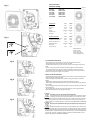
Fig. 1
+ -
% rh
+ -
T
Fig. 2
Fig. 3
Fig. 4
Fig. 5
Vulkan 100
Vulkan 100B
Vulkan 100L
Vulkan 100P
Vulkan 100T
Vulkan 100HT
EU / GUARANTEE CONDITIONS
-The producer grants a guarantee for a failure-free operation of the fan.
-The guarantee period is 24 months from the sale date.
-This Guarantee Certificate is valid only with a receipt confirming the date of pur-
chase.
- Claims under this guarantee should be made through the authorized dealer.
- The costs between of carriage to the dealer shall be borne by the purchaser.
- The producer shall not be liable for mechanical damage or when the purchaser
makes any construction changes in the product.
POLSKA / WARUNKI GWARANCJI
-
-
zakupu.
-
-
tora na nowy.
-
- W razie dokonania napraw lub zmian konstrukcyjnych przez osoby producent
Information for Users on Disposal of Old Equipment.
This symbol indicates that the electrical and electronic equipment should
not be disposed of as general household waste at its end-of-life. Instead,
the products should be handed over to the appliance collection points for
the recycling of electrical and electronic equipment., recovery and recycling in ac-
cordance with your national legislation and the Directive 2002/96/EC and 2006/66/
EC.
tu.
go przerobu., odzysku i recyklingu zgodnie z krajowym ustawodawstwem oraz w
zgodzie z Dyrektywami 202/96/EC i 206/66/EC
2009/07/07
Parametry techniczne Aero Vulkan
230 V 230 V
50 Hz 50 Hz
19 W 19 W
Wydatek powietrza 100 m3/h 120 m3/h
Klasa izolacji II II
IP-X4 IP-X4
Producer/Producent:
ELPLAST.com Sp.J.
ul. Konarskiego 20,
99-300 Kutno, Poland
e-mail: info@elplast.com

PRZEZNACZENIE
przewody wentylacyjne, w budynkach mieszkalnych zamieszka-
lub wybuch.
-
tym dzieci)
psychicznej.
- przeznaczony do zabawy dla dzieci.
-
-
do tego celu otwory w korpusie wentylatora.
-
-
lacji elektrycznej do listwy zaciskowej (3/Fig.1) zgodnie z wy-
-
tora.
-
-
ogniem.
-
wentylatora w wersji (HT) automatycznie po uzyskaniu wyma-
Wentylator pracuje w trybie czasowym w chwili kiedy dioda
-).
APPLICATION
The exhaust duct fans are ideal for bathrooms and toilet appli-
cations. They are used for supporting natural ventilation and
can be installed the areas with their own ventilation duct lines
with the exception of areas prone to corrosion and explosion.
- The equipment is not intended for use by persons (including
children) with reduced physical, sensory or mental ability.
- The equipment is not designed to be fun for children
INSTALLATION AND USAGE
- Please take off the front cover (1/Fig.1) using a small cross
screw driver (Screw—5/Fig.1).
- The fan should be fitted instead of the ventilation grill or in
the place prepared exactly for his kind of fans. For installation
please use the holes situated in a fan body.
- The fans with a pull switch and cable with a plug should be
plugged into the electric socket ~220-230V. In order to use the
fan please pull the cord to switch it on and off.
-The fans in basic version (B) with terminal block only or with
the electronic control systems (T, HT) should be connected
with the wiring system directly (Electric schema of fan installa-
tion: Fig.3,Fig.4,Fig.5). Please note that all wiring must com-
ply with current I.E.E. Wiring Regulations, if in any doubt con-
sult a qualified electrician.
-The fan with a pull switcher (4/Fig.1) enables temporary start-
ing and stopping of the fan by pulling the cord coming out of
the fan.
-The fixed cover should evenly adhere to the wall panel to
avoid distortion
- Every precaution should be taken to avoid reverse gas flow
to the open ventilation trunk or other open fire areas.
For the fans with the permanent electrical connection, the
electrical installation must have a switch with the distance
between the contacts of all poles of not less than 3 mm.
The (T) and (HT) fan versions have an embedded timer,
which needs to be set with an adjustable knob (T/Fig.2). The
range of the delay is 0,5-30 min. The activation is done by the
switch or in the (HT) fan version automatically when a certain
humidity level is reached.
When the LED light is pulsing the fan works in a timer mode.
The fan with a humidity sensor (HT) requires the setting of the
room humidity level. It is done by turning the adjustable knob
(% rh/Fig.2) to the extreme (-) position. The fan starts working
and the LED light sends continuous light. If the knob is turned
very slowly to the (+) position, the LED light begins pulsing. It
is the indication the required humidity level is reached.
The adjustments should be made in the dry room before
bathing or other water operations.
-
 1
1
-
 2
2


w innych językach
- English: ELPLAST Aero 100
Powiązane dokumenty
Inne dokumenty
-
Proline Power 2500 Operating Instructions Manual
-
Vents Silenta-M, Silenta-S Instrukcja obsługi
-
-
Barco MXRT-7400 instrukcja
-
 PowerWalker VFI 40000 TP 3/3 BI Instrukcja obsługi
-
-
Maico ECA 11 E Mounting And Operating Instructions
-
Master BG 100-200 Instrukcja obsługi
-
