
Kasutus- ja hooldusjuhend
Kuuma õhu generaator
BG 100 BG 150 BG 200
4031.811

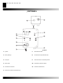
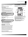
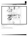
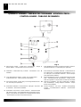
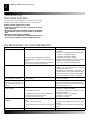
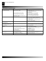
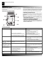
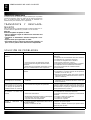
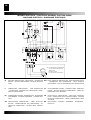
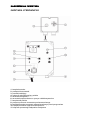
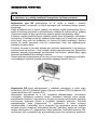
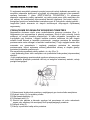
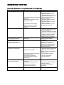
JUHTPANEEL
1. Juhttuli 7. Põleti kaitsmehoidik
2. Ainult juhtnupp 8. Ruumitermostaadi juhtmefiksaator
3. Voolujuhe 9. Ülekuumenemise termostaadi juhttuli
4. Põleti pistik 10. Ventilaatori peatamise juhttuli
5. Ventilaatori termostaat 11. Ventilaatori lähtestamine
6. Piirtermostaat käsitsi taaskäivitusega
BG 100, BG 150, BG 200
6
5
7
10
8
3
4
11
9
1
2
Joon. 0

KIRJELDUS
Hoiatus: Kasutamise ajal tuleb neljast küljest kaks jätta
avatuks, et vältida põlemiskambri ülekuumenemist.
BG ruumikütteseadmed on ette nähtud kasutamiseks väikestes
või keskmise suurusega ruumides ja hoonetes, kus on tarvis
püsiküttesüsteemi.
Soojus saadakse põlemise teel ja suitsusoojus suunatakse
värkesse õhku läbi põlemiskambri metallseinte ja soojusvaheti.
Suits ringleb sellist tüüpi põlemiskambris kaks korda.
Õhk ja suits läbivad eraldi torud, millest kumbki on keevitatud ja
tihendatud. Kui heitgaasid on pärast põlemist jahtunud, suuna-
takse need välja toru kaudu, mis tuleb ühendada korstna või
korstnalõõriga. Korsten või korstnalõõr peab olema suitsu
efektiivseks väljasuunamiseks piisavalt suur.
Põlemisel kasutatav õhk võetakse vahetult köetavast ruumist
või honest. Seetõttu on ülimalt oluline korraliku ventilatsiooni
olemasolu ruumis või hoones, et tagada piisava värske õhu
koguse pidev ringlus.
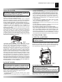
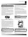
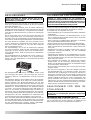
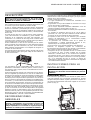
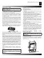
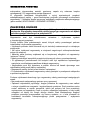
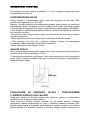
Õhuseadmel on neli külgava ja reguleeritavad ribid, mis
saadavad kuuma õhu soovitud suunda (Joon. 1).
BG kütteseadmed võivad töötada põletitega, mille jaoks
kasutatakse kütteõli, metaani (G20) või vedelgaasi (butaan
G30 ja propaan G31) ON-OFF tüübiga.
Tõsise rikke korral aktiveeritakse kolm kaitseseadet. Põleti juht-
seade, mis on paigaldatud põletile ja millel on taaskäivitusnupp,
peatab automaatselt põleti leegi kustumise korral. Käsitsi taas-
käivitatav ülekuumenemise termostaat L aktiveeritakse, kui
põlemiskambri temperatuur ületab seadistatud maksimaalse piiri;
hoiatustuli (9) süttib ja kütteseade lõpetab töö. Termorelee RM
aktiveeritakse, kui ventilaatori mootor hakkab kasutama maksi-
maalsest lubatud piirist rohkem elektrivoolu; hoiatustuli (10) süttib
ja kütteseade lõpetab töö.
Kui mõni nendest kaitseseadmetest aktiveerub, peate kontrollima
hoolikalt tegelikku probleemi enne, kui vajutate taaskäivitusnuppu
ja käivitate kütteseadme uuesti (“TÄHELDATUD VEAD,
PÕHJUSED JA ABINÕUD”).
ÜLDISED NÕUANDED
Hoiatus: Kasutada võib ainult tootja poolt valitud ja
tarnitud põleteid. Muud tüüpi põleti kasutamise korral ei
vasta kütteseade enam CE nõuetele.
Ruumikütteseade tuleb paigaldada, seadistada ja seda tuleb
kasutada vastavalt kehtivatele seadustele.
Allpool on toodud mõned üldised juhised, mida tuleb järgida:
•Järgige käesoleva juhendi juhiseid väga hoolikalt.
•Ärge paigaldage kütteseadet paikadesse, kus võib esineda
tule- või plahvatusoht.
• Kergestisüttiv materjal tuleb hoida kütteseadmest ohutus
kauguses (vähemalt 3 meetrit).
• Järgida tuleb kõiki tuleohutusnõudeid.
• Kütteseade peab paiknema korstna või korstnalõõri ja sobiva
elektrilise juhtkilbi lähedal.
• Ärge laske loomi ega lapsi kütteseadme lähedale.
• Pärast kasutamist veenduge, et katkestuslüliti on välja
lülitatud.Mistahes tüpi ruumikütteseadme kasutamisel on
kohustuslik:
• Mitte ületada kütteseadme maksimaalset soojuse
väljundtaset.
• Veenduda, et kütteseadmel on olemas piisav õhuvarustus ja
õhuringlus ning et miski ei takista õhu sissevõttu ja väljalaset.
Õhu liikumist võib takistada mitmel viisil, näiteks katete või
muude esemete asetamisega kütteseadmele või kütte-
seadme paigutamisega seinale või teisele suurele objektile
liiga lähedale. Ebapiisava õhuvarustuse korral võib põlemis-
kamber üle kuumeneda ja käsitsi taaskäivitatav ülekuumene-
mise termostaat aktiveeruda.
PAIGALDAMINE
Hoiatus: Alljärgnevaid toiminguid peab teostama
kvalifitseeritud personal.
KAUBAALUSE EEMALDAMINE
Ruumikütteseadme eemaldamiseks kaubaaluselt, millele see
on transportimiseks kinnitatud, kruvige lahti alumise paneeli
kinnituskruvi ja tõstke seade maha sobiva tõstevahendiga,
kasutades nelja punkti (a) (Joon. 2).
ELEKTRIÜHENDUSED JA SEADISTUSED
Hoiatus: Kütteseadme võrgutoide peab olema maanda-
tud ja sellel peab olema magnettermolüliti koos diferent-
siaaliga. Voolujuhe tuleb ühendada lülituskilbiga, millel
on katkestuslüliti.
Iga ruumikütteseadmega kuuluvad komplekti kaitse- ja juht-
seadmed, mis on seadme korrektse töö tagamiseks vältimatud.
Elektriline lülituskilp, ventilaatori termostaat ja käsitsi taas-
käivitatav ülekuumenemise termostaat on juba ühendatud.
Nüüd tuleb teostada järgmised toimingud:
KUUMA ÕHU GENERAATOR
a
a
a
a
Joon. 1
Joon. 2

KUUMA ÕHU GENERAATOR
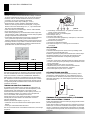
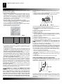
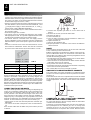
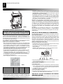
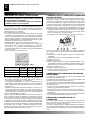
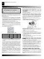
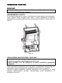
•Tabelis I on toodud kleebis kolmefaasilise toitega seadmetel.
Teostage elektriühendus pärast seda, kui olete läbi lugenud
kleebise, millel on toodud elektritoite andmed (Vt Tabel II).
Voolujuhe, mis ei kuulu seadmega komplekti:
peab olema HO7RN-F tüüpi (ristlõige 1, 5 mm²)
• tuleb ühendada seadme elektrilise lülituskilbiga juhtme-
klambri (3) abil ning ühendada klemmidega N, L ning ühe-
faasilise toite korral klemmidega N, R, S, T ja kolmefaasilise
toite korral (“ELEKTRISKEEM”).
• tuleb ühendada otse pealülituskilpi, millel on katkestuslüliti.
• ei tohi olla pikem kui 2 meetrit.
• Põleti tuleb paigaldada ja kinnitada kütteseadme külge sobi-
vate kruvidega. Põleti ja kütteseadme vahele tuleb paigutada
põletiga komplekti kuuluvad tihendid.
• Põleti tuleb ühendada kütusevarustusega ja põleti kalibreeri-
mine (“põleti kasutusjuhend”) peab vastama tehnilisel
kleebisel märgitud ruumikütteseadme maksimumvõimsusele.
• Ühendage tarvikud, nagu näiteks ruumitermostaadi või kella,
seadme elektrilise lülituskilbiga: elektrijuhe tuleb ühendada
juhtmefiksaatori (8) abil klemmidega 7 ja 8.
BG 100 BG 150 BG 200
Faaside arv 3 3 3
Pinge 230/400 230/400 230/400
Sagedus 50 50 50
Kui kõik need toimingud on teostatud, siis kontrollige hoolikalt,
kas kõik elektriühendused vastavad elektriskeemile ning kont-
rollige termostaadi F seadistust (“TEHNILISED ANDMED”).
Kütteseadme esmakordsel sisselülitamisel peate kontrollima,
kas ventilaator ei kasuta maksimaalsest lubatud piirist rohkem
elektrit. Lõpuks järgige põleti kasutusjuhendis toodud juhiseid,
et reguleerida põleti ruumikütteseadme sobivatele tehnilistele
andmetele vastavaks.
ÜHENDUS KUUMA ÕHU TORUDEGA
Ruumikütteseade tekitab soojust kuuma õhu väljastamise ja
hajutamise teel (Joon.1). Õhuseade kuulub komplekti ja selle
võib ühendada uute õhutorudega, kui kasutaja soovib
rahuldada konkreetseid vajadusi. Sellisel juhul ja eriti siis, kui
torude läbimõõt ja pikkus on muutunud või kui torupõlvede
arvu on muudetud, võib õhuväljund olla erinev.
Sellest tulenevalt on väga oluline kontrollida ja reguleerida
õhuväljundit, kui õhuseadmes või õhutorudes on tehtud
mistahes muudatusi.
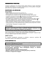
Kõikidel juhtudel tuleb tagada, et (Joon. 3):
• Ventilaator ei kasuta maksimaalsest lubatud piirist rohkem
elektrit.
• Õhukogus vastab ettenähtud tasemele.
Kui õhu vooluhulk erineb eelseadistatud väärtustest, siis toimige
järgmiselt:
1) Eemaldage sissetõmberest, mis paikneb seadme venti-
laatori mootori poolsel küljel.
2) Eemaldage kruvid (2) mootoriliugurilt.
3) Eemaldage rihm (1).
4) Keerake lahti poldid (3).
5) Pöörake rihmaratast päripäeva ja vastupäeva, et õhuvoolu
suurendada või vähendada.
6) Keerake kinni poldid (3).
7) Asetage sissetõmberest tagasi.
8) Korrake toiminguid 1-7, kuni õige õhu vooluhulk on
saavutatud.
VÄLJATÕMME
VÄLJATÕMME
Suitsuärastuslõõrid peavad olema terasest ja tüübiga T250
ning vastama standardile EN 1443.
Efektiivne põlemine ja põleti probleemivaba töö sõltuvad välja-
tõmbelõõri efektiivsusest. Seade tuleb ühendada korstna-
lõõriga vastavalt kehtivatele eeskirjadele ja järgmistele
juhistele:
• Suitsutoru peab olema võimalikult lühike ja kaldega ülespoole
• Torudes ei tohi olla järske paindeid ja torude läbimõõtu ei tohi
kunagi vähendada
• Igal kütteseadmel peab olema oma korsten
•
Väljatõmbelõõr peab vastama vähemalt minimaalsele
kohustuslikule tasemele tehnilistes andmetes
• Korstnalõõri pikkus peab olema 1 meeter.
PÕLEMISJÄÄKIDE ANALÜÜS
Andurid, mis kontrollivad põlemisjääkide koostist ja suitsu
temperatuuri, tuleb paigutada nii, nagu näidatud joonisel 4.
Kui need testid on teostatud, tuleb anduri jaoks puuritud ava
tihendada materjaliga, mis talub kõrget temperatuuri ja tagab
toru õhukindluse.
ÜHENDUS KÜTUSEVARUSTUSEGA JA ÜLEMINEK
ÜHELT GAASITÜÜBILT TEISELE
Põleti ühendamiseks kütusevarustusega järgige põleti kasutus-
juhendis toodud juhiseid
Põleti võib kasutada nii metaangaasi kui vedelgaasi. Käesolev
kütteseade on eelnevalt seadistatud metaangaasi G20 kasuta-
miseks. Üleminekuks metaangaasilt vedelgaasile või vastupidi
lugege põleti kasutusjuhendit, mis kuulub käesoleva juhendiga
komplekti.
230V- 3~- 50Hz
400V- 3~- 50Hz
1
4
3
2
200 mm
Tab. 1
Tab. 2
Joon. 3
Joon. 4
[V]
[Hz]
•

Põleti kasutusjuhendiga on kaasas ümbrik, milles on varuõhu-
klapp ja kleebis, mis näitab gaasitüüpi, mida põleti peaks
kasutama.
KASUTUSJUHISED
SISSELÜLITAMINE
• Seadke juhtnupp (2) positsioonile “0”.
• Lülitage sisse katkestuslüliti elektrilisel lülituskilbil.
• Seadme käsitsi juhtimise korral pöörake juhtnupp positsiooni
. Põleti käivitub, põlemiskamber soojeneb ja seejärel käivi-
tub ventilaator.
• Seadme automaatse töö korral seadke ruumitermostaat soovi-
tud tasemele ja pöörake juhtnupp (2) positsiooni : kütte-
seade käivitub ja peatub nüüd automaatselt.
• Kui kütteseade pärast ülalpool kirjeldatud toimingute teosta-
mist ei käivitu, lugege käesoleva juhendi Veaotsingu peatükki.
VÄLJALÜLITAMINE
Hoiatus: Ärge peatage kunagi kütteseadet, lülitades
lihtsalt elektrilise lülituskilbi katkestuslüliti välja.
Elektrivarustuse võib lahti ühendada alles siis, kui venti-
laator on täielikult peatunud.
Käsitsi juhtimise korral pöörake juhtnupp (2) positsiooni “0” või
lülitage automaatjuhtimise juhtnupp välja.
Põleti peatub, ventilaator lülitab aga ennast sisse ja välja, kuni
põlemiskamber on täielikult jahtunud.
VENTILATSIOON
Juhtnupu pööramisel sümbolile töötab kütteseade ventilaatori
püsirezhiimis.
HOOLDUS
Hoiatus: Alljärgnevaid toiminguid peab teostama kvalifitseeri-
tud personal.
Hoiatus: Enne mistahes hooldustööde teostamist tuleb
kütteseade vooluvõrgust lahti ühendada. Selleks:
• Peatage seade nii, nagu kirjeldatud ülalpool
• Lülitage välja katkestuslüliti elektrilisel lülituskilbil.
• Oodake, kuni kütteseade on jahtunud.
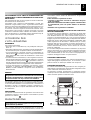
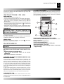
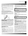
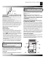
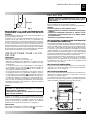
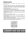
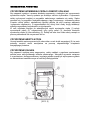
SOOJUSVAHETI JA PÕLEMISKAMBRI
PUHASTAMINE
Kütteseadme efektiivse töö tagamiseks tuleb soojusvahetit ja
põlemiskambrit puhastada pärast pikaajalist kasutamist ning
sagedamini, kui tahma koguneb liiga palju. Tahm koguneb
juhul, kui korstna väljatõmme pole piisav, kütus on madala
kvaliteediga, põleti on valesti reguleeritud või kütteseadet
lülitatakse liiga tihti sisse ja välja. Kui kütteseade hakkab
sisselülitamisel vibreerima, on tahma tõenäoliselt liiga palju.
Soojusvaheti (1) sisemiste osade juurde pääsemiseks
eemaldage põleti (2), eemaldage ülemine tagapaneel (3),
vaheti kontrollpaneelid (4) ja vaheplaadid (5). Eemaldage
tahm või võõrkehad tolmuimeja või torupuhastusseadmega.
VENTILAATORI PUHASTAMINE
Eemaldage mustus või võõrkehad sissetõmberesti võrgust
(6) ja puhastage vajaduse korral tiivik imemisseadmega.
PÕLETI PUHASTAMINE
Kütteseadme efektiivse töö tagamiseks peab volitatud hooldus-
tehnik põletit regulaarselt hooldama. Kõik puhastus-, hooldus-
ja reguleerimistööd tuleb teostada nii, nagu kirjeldatud põleti
kasutusjuhendis.
KÜTTESEADME TRANSPORT JA TEISALDAMINE
Kütteseadme teisaldamiseks või transportimiseks asetage see
kõrgendatud alusele ja tõstke kahveltõstukiga üles.
Hoiatus: enne seadme teisaldamist:
• Lülitage see välja nii, nagu kirjeldatud ülalpool.
• Ühendage elektrivarustus lahti, tõmmates pistiku
välja.
• Oodake, kuni kütteseade on jahtunud
• Ärge püüdke kunagi kütteseadet käsitsi tõsta.
See võib põhjustada vigastusi.
KUUMA ÕHU GENERAATOR
1
3
6
2
4
5
Joon. 5

KUUMA ÕHU GENERAATOR
VEAOTSING
AbinõuPõhjusProbleem
Kütteseade ei käivitu
2. Pealüliti vale positsioon
3. Ruumitermostaadi vale seadistus
4. Kaitseseade (põleti, termostaat L) jäi
pärast remonti uuesti käivitamata
1. Kontrollige pealüliti tööd ja positsiooni
1. Kontrollige voolujuhet
1. Kontrollige elektriühendusi
1. Kontrollige kaitsmeid
2. Seadke pealüliti õigesse positsiooni
3. Kontrollige ruumitermostaadi seadistust
3. Kontrollige ruumitermostaadi tööd
4. Vajutage vastavat taaskäivitusnuppu
Termostaat L aktiveerub
1. Kontrollige positsiooniregistreid, avasid jt.
1. Eemaldage võõrkehad õhutorudest ja ventilat-
sioonirestidest
1. Suurendage õhuvoolu ülekande reguleerimisega
mootori ja ventilaatori vahel
Termorelee RM aktiveerub
(hoiatustuli (9) süttib)
1. Ventilaatori liigne energiakulu
Põleti käivitub, leeki ei sütti ja
taaskäivituse tuli süttib
1. Põleti ei tööta korralikult
Ventilaator ei käivitu või käivitub
hilinemisega
1. Elektritoide puudub
2. F termostaat on rikkis
3. Mootorimähis põlenud või katkenud
4. Kondensaator põlenud
5. Mootorilaagrid blokeeritud
1. Kontrollige kaitsmeid
1. Kontrollige elektriühendusi
2. Kontrollige termostaati, seadistage ja vahetage
see, kui tarvis
3. Vahetage ventilaatori mootor
4. Vahetage kondensaator
5. Vahetage laagrid
Ventilaator vibreerib või tekitab
ebatavalist müra
1. Võõrkehad ventilaatori labadel
2. Ebapiisav õhuringlus
3. Veorihm on lõtv või liigendamata
1. Eemaldage võõrkehad
2. Eemaldage õhuringluse takistused
3. Reguleerige veorihma pingutust
Kutsuge volitatud hooldustehnik .1 Vale põleti.1 Ebapiisav soojus
1. Elektrivarustuse rike
1. Põlemiskamber on üle kuumenenud
1. Reguleerige ülekanne mootori ja ventilaatori
vahel
1. Vajutage taaskäivituse nuppu, et kütteseade
sisse lülitada. Kui sama probleem kordub,
kutsuge volitatud hooldustehnik
1. Kontrollige kütusevarustust

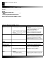
VASTATUSSERTIFIKAAT
Alljärgnev firma:
DESA Europe B.V. Postbus 271 - 4700 AG Roosendaal - NL
Deklareerib oma vastutusel, et seade
Kuuma õhu generaator
BG 100 - BG 150 - BG 200
Vastab järgmistele direktiividele:
98/37 CE, 91/368, 93/44, EMC 89/336, 92/31, 93/68, 73/23.
Roosendaal, 08/04/2004
Augusto Millan (tegevdirektor)

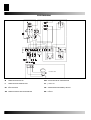
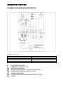
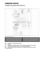
ELEKTRISKEEM
M VENTILAATORI MOTOR
RM VENTILAATORITE TERMORELEE
F VENTILAATORI TERMOSTAAT ST JUHTTULI
FB PÕLETI KAITSE SB VENTILAATORI PEATAMISE JUHTTULI
TM VENTILAATORITE KAUGKONTAKTOR BR PÕLETI
KÜTTEFILTER

ELEKTRISKEEM
TA RUUMITERMOSTAAT SL ÜLEKUUMENEMISE TERMOSTAADI JUHTTULI
PB PÕLETI
L PIIRTERMOSTAAT KÄSITSI TAASKÄIVITUSEGA
RV JUHTNUPP SOOJUS / O / AINULT VENTILATSIOON

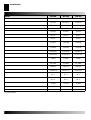
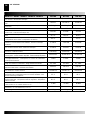
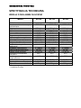
MUDEL
BG 100 BG 150 BG 200
Toide
230/240 V - 50 Hz
Õhuväljund
7.600 m³ 10.000 m³ 12.500 m³
Küttekulu
9,71 kg/h 14,71 kg/h 18,63 kg/h
Kütus
Gasolio - Õli - Heizöl - Gaasiõli - Kütus
Max. võimsus
115 kW 175 kW 220 kW
Efektiivsus
90,7 % 88,6 % 89,6 %
Suitsu temperatuur
C° 732C° 042
Ventilaatori energiakulu
1.780 W 2.340 kW 4.130 kW
Energiakulu kokku*
2.000 W 3.100 W 4.000 W
Suitsuvool*
232 Nm³/h 306 Nm³/h 400 Nm³/h
Saadaval olev staatiline rõhk
20 mm H2O 20 mm H2O 20 mm H2O
Põletatud gaaside rõhk*
1 mbar 1 mbar 1 mbar
Kohustuslik väljatõmbelõõr*
0,1 mbar 0,1 mbar 0,1 mbar
Lõõri läbimõõt
200 mm 200 mm 200 mm
Õhu väljalaskeosa
57x106 cm 59x117 cm 67x143 cm
Ventilaatori käivitustemperatuur
35 °C 35 °C 35 °C
Ohutu piirtemperatuuri seadistus
110 °C 85 °C 85 °C
Müratase 1 m kaugusel*
77 dBA 77 dBA 80 dBA
Mõõdud, Px Lx K
116x67x183 cm 171x69x183 cm 196x77x213 cm
Kaal
247 kg 297 kg 389 kg
*= Ecoflam põletiga
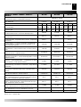
ÕLIVERSIOON

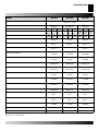
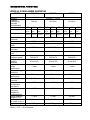
MUDEL
BG 100 BG 150 BG 200
Toide
230/240 V - 50 Hz
Õhuväljund
7.600 m³ 10.000 m³ 12.500 m³
Kütus
Kütusekulu
Gaasirõhk
Max. võimsus*
115 kW 175 kW 220 kW
Efektiivsus
90,7 % 88,6 % 89,6 %
Suitsu temperatuur
C° 732C° 042
Ventilaatori energiakulu
1.780 W 2.340 kW 4.130 kW
Energiakulu kokku*
2.000 W 3.100 W 4.000 W
Suitsuvool*
232 Nm³/h 306 Nm³/h 400 Nm³/h
Saadaval olev staatiline rõhk
20 mm H2O 20 mm H2O 20 mm H2O
Põletatud gaaside rõhk*
1 mbar 1 mbar 1 mbar
Kohustuslik väljatõmbelõõr*
0,1 mbar 0,1 mbar 0,1 mbar
Lõõri läbimõõt
200 mm 200 mm 200 mm
Õhu väljalaskeosa
57x106 cm 59x117 cm 67x143 cm
Ventilaatori käivitustemperatuur
35 °C 35 °C 35 °C
Ohutu piirtemperatuuri seadistus
110 °C 85 °C 85 °C
Müratase 1 m kaugusel*
77 dBA 77 dBA 80 dBA
Kaal
116x67x183 cm 171x69x183 cm 196x77x213 cm
Mõõdud, Px Lx K
247 kg 297 kg 389 kg
*= Ecoflam põletiga
Nm³/h= 15°C - 1013,25 mbar
G20 G30 G31
11,54
Nm³/h
9,08
kg/h
8,94
kg/h
20
mbar
29
mbar
37
mbar
G20 G30 G31
17,49
Nm³/h
13,75
kg/h
13,55
kg/h
20
mbar
29
mbar
37
mbar
G20 G30 G31
22,15
Nm³/h
17,42
kg/h
17,16
kg/h
20
mbar
29
mbar
37
mbar
GAASIVERSIOON

DESA ITALIA s.r.l.
via Tione, 12 - 37010 Pastrengo
(Verona) - Italy
www.desaitalia.com
DESA POLAND Sp. Z.o.o
ul Rolna 8, Sady
62-080 Tarnowo Podgorne, Poland
www.desapoland.pl -
DESA UK Ltd.
Unit 3 Easter Court Gemini
Business Park Warrington, Cheshire
WA5 7ZB United Kingdom

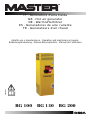
Libretto uso e manutenzione - Operation and maintenance manual -
Bedienungsanweisung - Manual del proprietario - Manuel de L’utilisateur
IT - Generatore d’aria Calda
GB - Hot air generator
DE - Warmlufterhitzer
ES - Generadores de aire caliente
FR - Generateurs d’air chaud
BG 100 BG 150 BG 200
4031.811

2
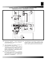
QUADRO COMANDI - TABLEAU DE COMMANDE - KONTROLLTAFEL -
CONTROL BOARD - TABLERO DE MANDOS
1. Spia tensone quadro - Control lamp - Kontrollampe - testigo
tensión tablero - Lampe temoin mise sous tension
7. Porta fusibile per bruciatore - Burner fuse holder - Sicherun-
gschalter für brenner - Porta fusible para quemador
2. Interruttore - Control knob only - Schalter - Conmutador - Com-
mutateur
8. Pressacabvo per termostato ambiente - Cable fastener for
room thermostat - Raumthermostat kabel führung - Pren-
sa cable para de termostato ambiente - Presse etoupe
pour thermostat d’ambiance
3. Cavo alimentazione elettrica - Power cord - Elektro kabel -
Cable alimentación - Cable electrique alimentation
9. Spia termostato di sicurezza - Overheat thermostat control
lamp - Überhitzungschutz kontrollampe - Testigo termo-
stato de seguridad - Lampe temoin securite de surchauffe
4. Presa per bruciatore - Burner plug - Sicherungschalter für bren-
ner - Enchufe para quemador
10. Spia blocco ventilatore - Fan stop control lamp - Ventilator
“aus” kontrollampe - Testigo bloqueo ventilador - Lampe
temoin arret ventilateur
5. Termostato ventilatore - Fan thermostat - Luftregler - Termosta-
to ventilador - Thermostat ventilateur
11. Riarmo ventilatore - Fan reset - Ventilator entriegelungs
schalter - Restablecimiento ventilador - Rearmement
ventilateur
6. Termostato di sicurezza a riarmo manuale - Limit thermostat
with manual restart - Sichereitsthermostat mit manueller entrie-
gelung - Termostato de seguridad con restablecimiento manual
- Thermostat de securite a rearmement manual
BG 100, BG 150, BG 200
6
5
7
10
8
3
4
11
9
1
2
Fig. 0

DESCRIZIONE
ATTENZIONE: Durante il funzionamento le alette non
devono esserecompletamente chiuse per evitare il surri-
scaldamentodella camera di combustione.
I generatori d’aria calda della serie BF sono destinati al riscalda-
mento di locali aventi medie o grandi dimensioni per i quali si
richiede un sistema di riscaldamento fi sso.
L’aria viene riscaldata utilizzando l’energia termica sviluppata
durante la combustione e trasmessa dai fumi caldi all’aria fresca
attraverso le superfi cie metalliche della camera di combustione,
del tipo a doppio giro di fumi, e dello scambiatore di calore.
Il canale di passaggio dell’aria e quello dei fumi sono separati
e realizzati con saldature e guarnizioni di tenuta. I prodotti della
combustione, dopo essersi raffreddati, sono convogliati ad un
condotto di scarico; tale condotto deve essere collegato ad un
camino o canna fumaria avente dimensioni tali da garantire
l’evacuazione dei fumi.
L’aria comburente, ossia quella necessaria alla combustione, viene
aspirata dal bruciatore che la preleva direttamente dall’ambiente
da riscaldare; tale ambiente, quindi, deve essere opportunamente
ventilato al fi ne di assicurare che il ricambio di aria sia suffi ciente.
Il condotto terminale di mandata dell’aria calda (10) é provvisto
di alette mobili da ruotare sino a indirizzare il fl usso di aria calda
nella direzione desiderata (cfr Fig. 1).
I generatori d’aria calda BG, possono funzionare con bru-
ciatori alimentati a gasolio, metano (G20) o GPL (butano, G30 e
propano, G31), aventi modalità di funzionamento ON-OFF.
Il funzionamento dell’apparecchio, infi ne, é controllato da tre
dispositivi di sicurezza che intervengono in caso di grave mal-
funzionamento. L’apparecchiatura di controllo del bruciatore,
montata sullo chassis del bruciatore stesso e dotata di pulsante
di riarmo, ne provoca l’arresto se la fi amma si spegne. Il termo-
stato di sicurezza a riarmo manuale, L, e il relé termico, RM, in-
tervengono arrestando il funzionamento del generatore: il primo
se la temperatura della camera di combustione supera il valore
limite preselezionato (la lampada (9) si illumina); il secondo se
l’assorbimento di corrente elettrica del motore del ventilatore su-
pera il valore limite (la lampada (10) si illumina). Se uno di questi
dispositivi di sicurezza interviene, si deve sempre ricercare la
causa dell’intervento ed eliminarla prima di premere il rispettivo
pulsante di riarmo e avviare il generatore (“INCONVENIENTI DI
FUNZIONAMENTO, CAUSE E RIMEDI”).
AVVERTENZE
ATTENZIONE: Possono essere utilizzati solamente i bru-
ciatori scelti eforniti dal costruttore. La marcatura CE della
macchinadecade se si sostituisce il bruciatore con un mo-
dello nonoriginale, seppure avente caratteristiche simili.
L’installazione, la regolazione e l’uso del generatore d’aria calda
devono essere eseguiti rispettando le regolamentazioni e le
leggi in vigore relative all’utilizzazione della macchina.
È buona regola assicurarsi che:
• le istruzioni contenute nel presente manuale siano seguite
scrupolosamente;
• il generatore non sia installato nelle aree a maggiore rischio di
incendio o di esplosione;
• materiali facilmente infi ammabili non siano depositati nelle vicinan-
ze dell’apparecchio (la distanza minima deve essere pari a 3 m);
• siano state adottate le misure necessarie per prevenire gli incendi;
• l’aerazione del locale nel quale si trova il generatore sia garan-
tita e sia suffi ciente al fabbisogno del generatore medesimo;
• l’apparecchio sia disposto nelle vicinanze di un camino e di un
quadro elettrico di alimentazione con caratteristiche conformi
a quelle dichiarate;
• il generatore sia controllato prima della messa in funzi-
one e sorvegliato regolarmente durante l’uso impedendo
l’avvicinamento di bambini e/o animali;
• al termine di ogni esercizio d’uso l’interruttore di sezionamento
sia disinserito.
È inoltre obbligatorio rispettare le condizioni di funzionamento
del generatore d’aria calda ed in particolare:
• non superare la potenza termica massima del focolare;
• assicurarsi che la portata d’aria non sia inferiore a quella nomi-
nale; si deve quindi controllare che non vi siano ostacoli od os-
truzioni ai condotti di aspirazione e/o di mandata dell’aria, come
teli o coperte adagiati sull’apparecchio, pareti od oggetti ingom-
branti vicini al generatore, etc. Se la portata d’aria è scarsa si
ha il surriscaldamento della camera di combustione e il conseg-
uente intervento del termostato di sicurezza a riarmo manuale.
ISTRUZIONI PER
L’INSTALLAZIONE
ATTENZIONE:Tutte le operazioni descritte in questo para-
grafo devono essere eseguite solo da personale profes-
sionalmente qualifi cato.
RIMOZIONE DEL PALLET
Per rimuovere il generatore d’aria calda dal pallet sul quale è
montato per il trasporto, svitare le viti di fi ssaggio del pannello
inferiore al pallet e sollevare la macchina con un adeguato orga-
no di sollevamento collegato nei quattro punti (a) (Fig. 2).
COLLEGAMENTI ELETTRICI E REGOLAZIONI
ATTENZIONE:La linea elettrica di alimentazione del genera-
tore deve essere provvista di messa a terra e di interruttore
magneto-termico con differenziale.
Il cavo di alimentazione elettrica deve essere allacciato ad
un quadro elettrico munito di interruttore di sezionamento.
La dotazione di serie del generatore d’aria calda comprende tutti
i dispositivi di controllo e di sicurezza indispensabili per il funzio-
namento della macchina: quadro elettrico, termostato ambiente
GENERATORE D’ARIA CALDA
3
IT
a
a
a
a
Fig. 2
Fig. 1

(2), termostato del ventilatore e termostato di sicurezza a riarmo
manuale sono già collegati.
Si devono ancora effettuare:
• l’allacciamento alla rete elettrica, da eseguirsi dopo aver con-
trollato le caratteristiche di alimentazione elettrica riportate
sull’etichetta adesiva (in Tab. I è indicata l’etichetta applicata
alle macchine con alimentazione trifase, in Tab. II il tipo di
alimentazione); il cavo di alimentazione, che non é compreso
nella dotazione di serie, deve essere:
• del tipo H07RN-F con sezione del fi lo pari a 1,5 mm²,
• inserito nel quadro elettrico del generatore attraverso il pressa-
cavo (3) e collegato ai morsetti N, L e , se monofase, o N, R,
S, T e , se trifase (“SCHEMA ELETTRICO”),
• collegato direttamente ad un quadro elettrico di alimentazione
munito di interruttore di sezionamento e
• avere lunghezza non superiore a 2 m;
BG 100 BG 150 BG 200
Numero di fasi 3 3 3
Tensione 230/400 230/400 230/400
Frequenza 50 50 50
• il montaggio del bruciatore, da fi ssare al generatore con le
apposite viti avendo cura di interporre la guarnizione fornita a
corredo del bruciatore;
• il collegamento del bruciatore alla linea di alimentazione del
combustibile e la taratura del bruciatore (manuale d’uso del
bruciatore) concordemente alla potenza termica max del ge-
neratore indicata sull’etichetta dei dati tecnici;
• l’eventuale collegamento del termostato ambiente o di altri ac-
cessori dell’impianto (come ad es., l’orologio) il cui cavo elet-
trico deve essere inserito nel quadro elettrico del generatore
attraverso il pressacavo (8) e collegato ai morsetti 7 e 8 della
morsettiera (“SCHEMA ELETTRICO”).
Dopo aver eseguito tutte le operazioni descritte e prima di av-
viare la macchina, é opportuno controllare i collegamenti elettrici
effettuati con quelli riportati sullo schema elettrico e controllare
la taratura del termostato F (“LA TABELLA DELLE CARATTE-
RISTICHE TECNICHE”). Al primo avviamento si deve sempre
controllare che l’assorbimento di corrente del ventilatore non
superi quello dichiarato.
Il bruciatore, infi ne, deve essere regolato seguendo le istruzioni
riportate sul relativo manuale d’uso concordemente ai dati tecni-
ci indicati per il generatore d’aria calda.
COLLEGAMENTO AI CONDOTTI DI MANDATA DELL’ARIA
CALDA
Il generatore d’aria calda è predisposto per il funzionamento condif-
fusione dell’aria attraverso il condotto di Fig. 1. Tale dispositivo può
essere sostituito con condotti di sezione opportuna collegati in serie,
sespecifi che esigenze di impiego lo richiedono; poiché il valore della
portata d’aria può variare si devono svolgere controlli e regolazioni
che devono sempre essere eseguiti ogni qualvolta cambiamenti signi-
fi cativi siano apportati al circuito di distribuzione dell’aria calda (modifi -
che alla lunghezza o al diametro dei tubi, al numero di curve, ecc.).
Si deve:
• verifi care che la corrente assorbita dal motore del ventilatore
non sia superiore al valore dichiarato;
• verifi care che la portata d’aria sia pari a quella nominale.
Se il valore della portata d’aria é diverso da quello specifi cato, si
devono effettuare le seguenti operazioni (Fig. 3):
1) smontare ed estrarre la griglia di aspirazione del lato motore-
ventilatore;
2) svitare la vite (2) della slitta del motore;
3) togliere la cinghia (1);
4) allentare i grani (3);
5) ruotare la parte mobile (4) della puleggia svitandola o avvitan-
dola per diminuire o aumentare rispettivamente la velocità di
rotazione e, quindi, la portata d’aria del ventilatore;
6) bloccare i grani (3);
7) montare la griglia di aspirazione;
8) ripetere le operazioni da (1) a (7) sino a quando la portata
dell’aria non raggiunge il valore nominale.
COLLEGAMENTO AL CONDOTTO DI EVACUAZIONE DEI
FUMI
I condotti di evacuazione dei fumi devono essere in acciaio e
del tipo T250 conformi alla norma EN1443.
Il rendimento di combustione ed il corretto funzionamento del
bruciatore dipendono dal tiraggio del camino. Il collegamento
alla canna fumaria deve essere effettuato rispettando le disposi-
zioni delle leggi vi-genti e osservando le seguenti prescrizioni:
• il percorso del raccordo fumario deve essere il più breve pos-
sibile e con pendenza ascendente;
• si devono evitare curve strette e riduzioni di sezione;
• deve essere predisposto un camino per ogni generatore di
aria calda;
• il tiraggio della canna fumaria deve essere almeno pari a quel-
lo prescritto
• la canna fumaria deve avere lunghezza pari ad 1 metro.
ANALISI DEI PRODOTTI DELLA COMBUSTIONE
Le sonde per il controllo della composizione dei prodotti della
combustione e della temperatura dei fumi devono essere posi-
zionate come indicato in Fig. 4.
Al termine delle prove di collaudo il foro praticato per l’inse-
rimento delle sonde deve essere sigillato con materiale che
garantisca la tenuta del condotto e sia resistente alle elevate
temperature.
GENERATORE D’ARIA CALDA
4
IT
200 mm
❏ 230V - 3~ - 50Hz
❏ 400V - 3~ - 50Hz
1
4
3
2
Tab. 1
Tab. 2
Fig. 3
Fig. 4
[V]
[Hz]

COLLEGAMENTO ALLA LINEA DI ALIMENTAZIONE DEL
COMBUSTIBILE E TRASFORMAZIONE DA UN TIPO DI GAS
AD UN ALTRO
Tale collegamento deve essere eseguito secondo le indicazioni
del manuale d’uso del bruciatore.
Il bruciatore a gas é del tipo a policombustibile e, quindi, può
funzionare con gas metano o G.P.L.. Il generatore d’aria calda é
fornito con il bruciatore già predisposto per il funzionamento con
gas metano, G20. Per la trasformazione da gas metano a G.P.L.
o viceversa si devono seguire le istruzioni del manuale d’uso
del bruciatore. Tale manuale è allegato al presente con busta
contenente l’eventuale orifi zio calibrato da sostituire (manuale
d’uso del bruciatore) e un’etichetta adesiva riportante il tipo di
gas per il quale la macchina è stata predisposta.
ISTRUZIONI PER
L’UTILIZZAZIONE
AVVIAMENTO
Per avviare il generatore:
• Assicurarsi che il commutatore (1) sia predisposto sulla posi-
zione “0” .
• Alimentare elettricamente il generatore agendo sull’interruttore
di sezionamento posto sul quadro elettrico di alimentazione.
• Se il funzionamento è manuale, spostare il commutatore (2)
nella posizione : il bruciatore si avvia e dopo alcuni minuti di
preriscaldamento della camera di combustione si avvia anche
il ventilatore.
• Se il funzionamento è automatico, si deve regolare il valore de-
siderato della temperatura del termostato ambiente e spostare
il commutatore (2) nella posizione : il generatore si avvia e si
arresta automaticamente quando la temperatura dell’ambiente
è rispettivamente minore o maggiore del valore selezionato.
• Se dopo tali operazioni il generatore non funziona, si deve
consultare il paragrafo “INCONVENIENTI DI FUNZIONA-
MENTO, CAUSE E RIMEDI” e scoprire la causa del mancato
funzionamento.
ARRESTO
ATTENZIONE: Non si deve mai arrestare il funzionamento
del generatore disinserendo l’interruttore di sezionamento
del quadro di alimentazione. L’alimentazione elettrica deve
essere disinserita solo dopo l’arresto del ventilatore.
Per arrestare l’apparecchio bisogna agire sul commutatore (2),
spostandolo nella posizione “0”, se il funzionamento è manuale,
o sul termostato ambiente se il funzionamento è automatico. Il
bruciatore si arresta e il ventilatore continua a funzionare, av-
viandosi più volte, fi no al completo raffreddamento della camera
di combustione.
VENTILAZIONE
Per ottenere il funzionamento del generatore nel modo di sola
ventilazione continua, si deve spostare il commutatore (2) nella
posizione con simbolo .
MANUTENZIONE
ATTENZIONE: Tutte le operazioni descritte in questo
paragrafo devono essere eseguite solo da personale pro-
fessionalmente qualifi cato.
Per il regolare funzionamento dell’apparecchio è necessario
effettuare periodicamente le seguenti operazioni, avendo cura
di escludere la linea elettrica di alimentazione del generatore
prima di iniziare.
Prima di iniziare l’ operazione si deve:
• Arrestare la macchina secondo le indicazioni del para-
grafo precedente,
• Disinserire l’alimentazione elettrica agendo sull’interruttore
di sezionamento posto sul quadro elettrico di alimenta-
zione
• Attendere che il generatore si raffreddi.
PULIZIA DELLO SCAMBIATORE DI CALORE E DELLA CA-
MERA DI COMBUSTIONE
Per mantenere elevata l’effi cienza e prolungare la durata della
macchina, l’operazione descritta in questo paragrafo deve es-
sere effettuata almeno una volta al termine della stagione di
esercizio o più frequentemente se vi è un’eccessiva quantità di
fuliggine; la presenza di quest’ultima può dipendere dal difettoso
tiraggio del camino, dalla pessima qualità del combustibile, dalla
cattiva regolazione del bruciatore o dall’alternarsi più o meno
frequente delle fasi di accensione ed arresto del bruciatore. È
opportuno prestare attenzione durante il funzionamento: pul-
sazioni all’avviamento possono essere dovute ad eccessiva
presenza di fuliggine.
Per accedere alla parte interna dello scambiatore (1), dopo aver
rimosso il bruciatore (2), si deve smontare il pannello posteriore
superiore (3) e quello d’ispezione dello scambiatore (4) estra-
endo i turbolenziatori (5): con uno scovolo o un’aspirapolvere si
asportano la fuliggine residua e le parti estranee.
PULIZIA DEL VENTILATORE
Si devono asportare eventuali corpi estranei intrappolati fra le
maglie della griglia di aspirazione (6) e, se necessario, si deve
pulire la ventola con utensili per soffi are aria compressa.
PULIZIA DEL BRUCIATORE
Per il buon funzionamento del generatore si deve eseguire pe-
riodicamente la manutenzione del bruciatore rivolgendosi ad un
centro autorizzato di assistenza tecnica.
Le operazioni di pulizia, manutenzione e regolazione devono
comunque essere svolte attenendosi scrupolosamente alle spe-
cifi che istruzioni riportate sul manuale d’uso.
GENERATORE D’ARIA CALDA
5
IT
1
3
6
2
4
5
Fig. 5

TRASPORTO E
MOVIMENTAZIONE
Per il trasporto e la movimentazione la macchina deve essere
adagiata su una pedana e sollevata con un carrello elevatore.
Prima di spostare l’apparecchio si deve:
Prima di spostare l’apparecchio si deve:
• Arrestare la macchina secondo le indicazioni del para-
grafo “ARRESTO”
• Disinserire l’alimentazione elettrica agendo sull’interruttore
di sezionamento posto sul quadro elettrico di alimenta-
zione
•Attendere che il generatore si raffreddi.
• Non tentare mai il sollevamento manuale del generatore: il
peso eccessivo potrebbe produrre danni fi sici rilevanti.
GENERATORE D’ARIA CALDA
6
IT
INCONVENIENTI DI FUNZIONAMENTO
Guasto Causa Rimedio
L’apparecchio non parte 1.Alimentazione elettrica mancante
2.Posizione errata dell’interruttore generale
3.Funzionamento irregolare del termostato am-
biente
4.Dispositivo di sicurezza (bruciatore, termostato
L) non riarmato dopo una riparazione
1.Verifi care la funzionalità e la posizione dell’
interruttore
1.Verifi care le caratteristiche della linea elettrica
1. Verifi care i collegamenti elettrici
1. Controllare l’integrità dei fusibili
2.Selezionare la posizione corretta
3.Verifi care che la posizione del T.A.sia corretta
3. Verifi care la funzionalità del termostato
4. Premere il rispettivo pulsante di riarmo
Intervento del termostato L 1.Surriscaldamento della camera di combustione 1.Controllare la portata di combustibile
1.Verifi care la corretta posizione di eventuali
serrande, bocchette, etc.
1.Rimuovere eventuali parti intrappolate nei
condotti dell’aria o nelle griglie di ventilazione
1. Aumentare la portata d’aria variando il rappor-
to di trasmissione tra motore e ventilatore
Intervento del relé termico RM
(la lampada (9) si illumina)
1. Eccessivo assorbimento di corrente del motore
del ventilatore
1. Regolare il rapporto di trasmissione tra il mo-
tore e il ventilatore
Il bruciatore si avvia, la
fi amma non si accende e la
spia del pulsante di riarmo si
illumina
1.Funzionamento irregolare del bruciatore 1.Se dopo aver premuto il pulsante di riarmo e
aver avviato il generatore l’inconveniente si ri-
pete per la seconda volta, rivolgersi al Servizio
di Assistenza Tecnica
Il ventilatore non si avvia o si
avvia in ritardo
1.Alimentazione elettrica mancante
2.Guasto del termostato F
3.Avvolgimento del motore bruciato o interrotto
4.Condensatore del motore bruciato
5.Cuscinetti del motore bloccati
1.Controllare l’integrità dei fusibili
1.Verifi care i collegamenti elettrici
2.Controllare il termostato, regolarlo ed even-
tualmente sostituirlo
3.Sostituire il motore del ventilatore
4.Sostituire il condensatore
5.Sostituire i cuscinetti
Rumorosità o vibrazioni del
ventilatore
1.Corpi estranei depositati sulle pale del ventila-
tore
2.Scarsa circolazione di aria
3. Cinghia di trasmissione allentata o non allinea-
ta
1.Asportare le parti estranee
2.Eliminare ogni possibile ostacolo al passaggio
dell’aria.
3. Regolare la tensione della cinghia di trasmis-
sione
Riscaldamento insuffi ciente 1.Capacità insuffi ciente del bruciatore 1.Rivolgersi al Servizio di Assistenza Tecnica

DESCRIPTION
Warning: During use, two of the four sides must be left open
so as to avoid overheating of the combustion chamber.
BG space heaters have been designed for use in small to me-
dium-sized rooms and buildings where a fi xed heating system
is required.
Heat is produced by combustion and the heat from the smoke is
transmitted to the fresh air through the metal walls of the combu-
stion chamber and the heat exchanger. Smoke circulates twice
in this type of combustion chamber.
Air and smoke pass through separated ducts, both of which are
welded and sealed. When, after combustion, the waste gases
have cooled down, they are expelled through a duct which must
be connected to a chimney or chimney fl ue. The chimney or
chimney fl ue must be big enough to guarantee that the smoke
is expelled effi ciently.
The air which is used in combustion is aspirated directly from the
room or building which is being heated. It is therefore of utmost
importance that the room or building is properly ventilated to
guarantee the continual circulation of enough fresh air.
The air head has four lateral openings and adjustable fi ns which
send the hot air in the desired direction (Fig. 1).
BG heaters can operate with burners thatare fuelled by heating
oil, methane (G20) or LPG (butane G30 andpropane G31) of the
ON-OFF type.
There are three safety devices which are activated in case of se-
rious malfunction. The Burner Control Device, which is mounted
on the burner and has a restart button, automatically stops the
burner if the fl ame goes out. The Overheat Thermostat, L, of the
manual restart type, is activated if the temperature of the com-
bustion chamber rises above the set maximum limit; the warning
light (9) lights up and the heater stops working. The Thermal
Relay, RM, is activated if the fan motor starts using more electric
current than the maximum permitted limit; the warning light (10)
lights up and the heater stops working.
If any of these safety devices are activated you should check
carefully what the problem actually is before pressing the restart
button and starting the heater up again (“OBSERVED FAULTS,
CAUSES AND REMEDIES”).
GENERAL ADVICES
Warning: Only the burners which are chosen and sup-
plied by the manufacturer can be used. If another type of
burner is used the heater will no longer comply with CE
regulations.
The space heater must be installed, set up and used in accor-
dance with existing laws.
Here are a few general guidelines which should be followed:
•Follow the instructions in this booklet very carefully.
•Don’t install the heater in places where there may be a risk of
fi re or explosion.
• Infl ammable material should be kept at a safe distance from
the heater (Minimum 3 meters).
• All fi re prevention regulations must be adhered to.
• The room or building that is being heated must be suffi ciently
ventilated so that the heater has enough air to function pro-
perly.
• The heater must be near a chimney or chimney fl ue and a sui-
table electric switchboard.
• Don’t let animals or children near the heater.
• After use make sure the disconnecting switch is off.
When using any type of space heater it is obligatory:
• not to exceed the maximum level of heat output of the furna-
ce.
• to make sure that there is adequate air circulation and air sup-
ply to the heater and that nothing is obstructing the aspiration
and expulsion of air. Movement of air may be obstructed in
various ways including placing covers or other objects on the
heater or positioning the heater too near a wall or other large
object. If there is insuffi cient air supply the combustion cham-
ber overheats and the overheat thermostat with manual restart
is activated.
INSTALLATION
Warning: Qualifi ed personnel must carry out the following
operations.
REMOVAL OF THE PALLET
To remove the space heater from the pallet on which it is atta-
ched for the transport, unscrew the fi xing screw of the inferior
panel and lift the machine with a suitable mean of lifting using
the four points (a) (Fig. 2).
ELECTRICAL CONNECTIONS AND SETTINGS
Warning The mains supply to the heater must be earthed
and have a magneto-thermal switch with differential.
The power cord must be connected to a switchboard tha-
th as a disconnecting switch.
Every space heater is supplied along with the safety and control
devices which are indispensable to the correct functioning of the
unit.
The electric switch board, the fan thermostat and the overheat
thermostat with manual restart have already been connected.
The following operations must now be carried out:
HOT AIR GENERATOR
7
GB
a
a
a
a
Fig. 1
Fig. 2

HOT AIR GENERATOR
8
GB
• Table I shows the adhesive label on units which have three-phase
supply. Connect to the electricity supply having read the adhesive
label that details electricity supply characteristics (See Table II).
The power cord, which is not supplied with the heater:•must be
of the HO7RN-F type (section 1, 5 mm²)
• must be connected to the unit electric switchboard by means of
the cable fastener (3) and connected to the terminals N, L and
,if single-phase supply, or to the terminals N, R, S, T and ,
if three-phase supply (“WIRING DIAGRAM”).
• must be connected directly to a mains switchboard that has a
disconnecting switch.
• must not be longer than 2 meters.
• The burner must be mounted and attached to the heather
with appropriate screws. The gaskets supplied with the burner
should be placed between the burner and the heater.
• The burner must be connected to the fuel supply and the
burners calibration (“burner Instruction manual”) unanimously
with themaximun space heater power signed on the technical
label.
• Connect accessories such as the room thermostat or clock to
the unit electric switchboard: electric wire must be connected
by means of the cable fastener (8) to the terminals 7 and 8.
BG 100 BG 150 BG 200
Number of phases 3 3 3
Tension 230/400 230/400 230/400
Frequency 50 50 50
Having completed all these operations check carefully that all
electrical connections correspond to the wiring diagram and
check the setting of thermostat F (“TECHNICAL SPECIFICA-
TIONS”). When the heateris fi rst turned on you must check that
the fan does not use more electricity than the maximum permit-
ted limit. Finally, follow the instructions in the Burner Instruction
Manual to regulate the burner unanimously to the suitable tech-
nical data for the space heater.
CONNECTION TO HOT AIR DUCTS
The space heater provides heat by releasing and dispersing hot
air (Fig.1). An airhead is supplied and it can be connected to new
air ducts if the user wishes to satisfy specifi c needs. In this case
and in particular if the diameter and length of the ducts have
been changed or if the number of bends has been modifi ed, air
output may vary. Consequently it is very important to check and
regulate air output when any modifi cation is made to airheads or
air ducts. In all circumstances you must ensure that (Fig. 3):
• The fan does not use more electricity than the maximum per-
mitted limit.
• The volume of air fl ow corresponds to the recommended le-
vel.
If the volume of fl ow rate air differs from preset values proceed
as follows:
1) Remove the aspiration grill which is on fan motor side of
theunit.
2) Remove the screws (2) from the motor slide.
3) Remove the belt (1).
4) Loosen the bolts (3).
5) Turn the pulley clockwise and anti-clockwise in order to in-
crease or reduce the volume of air.
6) Tighten the bolts (3).
7) Put back the aspiration grill.
8) Repeat operations 1-7 until the correct volume of airfl ow ha-
sbeen achieved.
DRAFT
The evacuation smoke fl ues have to be in steel and of the kind
T250, conforming to the norm EN 1443.
Effi cient combustion and trouble-free working of the burner de-
pend on effi cient fl ue draft. The unit must be connected to the
chimney fl ue in accordance with current legal regulations and in
line with the following guidelines:
• The tube that carries the smoke should cover as short a distan-
ce as possible and should slant upwards
• There should be no sharp bends in the tubes and the diameter
of the tubes must never be reduced
• Every heater must have its own chimney
• Flue draft must at least correspond to the minimum compulsory
level in the Technical Specifi cations
• the chimney fl ue has to have a length of 1 meter.
ANALYSIS OF COMBUSTION WASTE PRODUCTS
The probes which check the composition of combustion waste
products and smoke temperature must be positioned as indica-
ted in Fig. 4.
When these tests have been completed the hole that was drilled
for the probe must be sealed with a material which is resistant
to high temperatures and which ensures that the tube remains
airtight.
CONNECTION TO FUEL SUPPLY AND CHANGING
FROM ONE TYPE OFGAS TO ANOTHER
To connect the burner to the fuel supply, follow the instructions
in the Burner Instruction Manual
The burner can use both methane gas and LPG. This heater has
been predisposed to use methane gas, G20. To change from
methane gas to LPG or vice versa consult the Burner Instruc-
tion Manual which accompanies this manual. With the Burner
❏ 230V - 3~ - 50Hz
❏ 400V - 3~ - 50Hz
1
4
3
2
200 mm
Tab. 1
Tab. 2
Fig. 3
Fig. 4
[V]
[Hz]
Strona się ładuje...
Strona się ładuje...
Strona się ładuje...
Strona się ładuje...
Strona się ładuje...
Strona się ładuje...
Strona się ładuje...
Strona się ładuje...
Strona się ładuje...
Strona się ładuje...
Strona się ładuje...
Strona się ładuje...
Strona się ładuje...
Strona się ładuje...
Strona się ładuje...
Strona się ładuje...
Strona się ładuje...
Strona się ładuje...
Strona się ładuje...
Strona się ładuje...
Strona się ładuje...
Strona się ładuje...
Strona się ładuje...
Strona się ładuje...
Strona się ładuje...
Strona się ładuje...
Strona się ładuje...
Strona się ładuje...
Strona się ładuje...
Strona się ładuje...
Strona się ładuje...
Strona się ładuje...
Strona się ładuje...
Strona się ładuje...
Strona się ładuje...
Strona się ładuje...
Strona się ładuje...
Strona się ładuje...
-
 1
1
-
 2
2
-
 3
3
-
 4
4
-
 5
5
-
 6
6
-
 7
7
-
 8
8
-
 9
9
-
 10
10
-
 11
11
-
 12
12
-
 13
13
-
 14
14
-
 15
15
-
 16
16
-
 17
17
-
 18
18
-
 19
19
-
 20
20
-
 21
21
-
 22
22
-
 23
23
-
 24
24
-
 25
25
-
 26
26
-
 27
27
-
 28
28
-
 29
29
-
 30
30
-
 31
31
-
 32
32
-
 33
33
-
 34
34
-
 35
35
-
 36
36
-
 37
37
-
 38
38
-
 39
39
-
 40
40
-
 41
41
-
 42
42
-
 43
43
-
 44
44
-
 45
45
-
 46
46
-
 47
47
-
 48
48
-
 49
49
-
 50
50
-
 51
51
-
 52
52
-
 53
53
-
 54
54
-
 55
55
-
 56
56
-
 57
57
-
 58
58


w innych językach
Powiązane artykuły
-
Master GREEN 70-200 Instrukcja obsługi
-
-
-
-
-
-
-
-
-
Inne dokumenty
-
SOVELOR F30 Instrukcja obsługi
-
Steba 39.02.00 Karta katalogowa
-
Kroll PX105 Instrukcja obsługi
-
Mark GNSE series Technical Manual
-
 MALTEC Nagrzewnica Gazowa Grzejnik z Dmuchawą GAS-2500Wt Instrukcja obsługi
-
BALTUR TBG 60 ME 50Hz Use and Maintenance Manual
-
-
-
-
