
INSTALLATION AND MAINTENANCE MANUAL
HPWH 2.1 200/260 U02
HPWH 2.1 200/260 U02 S
EN DOMESTIC HOT WATER HEAT PUMP
Instruction for installation and maintenance
DE WARMWASSER – WÄRMEPUMPE
Montage-, Betriebs- und Wartungsanleitung
PL POMPY CIEPŁA DO CIEPŁEJ WODY
INSTRUKCJA MONTAŻU I URUCHOMIENI
NL WARMTEPOMP VOOR SANITAIR WARM WATER
Installatie- en onderhoudshandleiding
205101-N1-REV6

1

2
Contents
1. [EN] INTRODUCTION .................................................................................................................................4
2. TRANSPORT AND HANDLING ......................................................................................................................5
3. DESIGN CHARACTERISTICS ..........................................................................................................................8
4. IMPORTANT INFORMATION .................................................................................................................... 10
5. INSTALLATION AND CONNECTION .......................................................................................................... 11
6. COMMISSIONING. .................................................................................................................................... 16
7. OPERATING MODES. USER INTERFACE. INITIAL CONTROLLER ADJUSTMENT. ........................................ 17
8. CONTROLLER ADJUSTMENT. PARAMETERS............................................................................................. 21
9. EXTERNAL CONNECTIVITY ........................................................................................................................ 23
10. MAINTENANCE AND CLEANING. .............................................................................................................. 25
11. TROUBLESHOOTING ................................................................................................................................ 27
12. DISPOSAL. ................................................................................................................................................ 29
13. GUARANTEE. ............................................................................................................................................ 30
14. PRODUCT FICHE – Outdoor air heat pump (placed indoor side (EN16147:2017) ................................... 31
1. [DE] EINLEITUNG .................................................................................................................................... 32
2. TRANSPORT UND HANDHABUNG ............................................................................................................ 33
3. ALLGEMEINE BESCHREIBUNG DES GERÄTS ............................................................................................ 36
4. WICHTIGE INFORMATION ........................................................................................................................ 38
5. EINBAU UND ANKOPPELN ....................................................................................................................... 39
6. INBETRIEBNAHME.................................................................................................................................... 45
7. ARBEITSMODI. ANWENDERSCHNITTSTELLE. ANFÄNGLICHE EINSTELLUNGEN DES GERÄTS. ................. 45
8. EINSTELLUNGEN DER STEUERUNG. KENNZAHLEN .................................................................................. 49
9. ÄUSSERE VERBINDUNG. .......................................................................................................................... 52
10. WARTUNG UND REINIGUNG. .................................................................................................................. 55
11. BESEITIGUNG VON STÖRUNGEN. ............................................................................................................ 56
12. ENTSORGUNG ALS ABFALL. ..................................................................................................................... 59
13. GARANTIEBEDINGUNGEN. ....................................................................................................................... 59
14. PRODUKTKARTE – Thermopumpe mit Außenluft (für inneren Einbau (EN16147:2017) ........................ 61
1. [NL] INLEIDING ...................................................................................................................................... 62
2. VERVOER EN MANIPULATIE ..................................................................................................................... 63
3. ALGEMENE BESCHRIJVING VAN HET TOESTEL ........................................................................................ 66
4. BELANGRIJKE INFORMATIE ...................................................................................................................... 69
5. INSTALLATIE EN AANSLUITING ................................................................................................................ 70
6. INBEDRIJFSTELLING .................................................................................................................................. 75

3
7. BEDRIJFSMODI. GEBRUIKERSINTERFACE. OORSPRONKELIJKE INSTELLINGEN VAN HET TOESTEL. ......... 75
8. BEDIENINGSINSTELLINGEN. PARAMETERS ............................................................................................... 79
9. EXTERNE AANSLUITING. ........................................................................................................................... 82
10. ONDERHOUD EN REINIGING ..................................................................................................................... 84
11. FOUTEN OPLOSSEN. ................................................................................................................................. 86
12. VERWIJDEREN EN AFVOEREN ................................................................................................................... 89
13. GARANTIE. ................................................................................................................................................ 89
14. PRODUCTKAART – Warmtepompgebruikmakend van buitenlucht (voorinstallatiebinnenshuis
(EN16147:2017) .................................................................................................................................................... 91
1. [PL] WSTĘP .............................................................................................................................................. 92
2. TRANSPORT I OBSŁUGA ............................................................................................................................ 93
3. OGÓLNY OPIS URZĄDZENIA ...................................................................................................................... 96
4. WAŻNE INFORMACJE ................................................................................................................................ 99
5. MONTAŻ I PODŁĄCZENIE ........................................................................................................................ 100
6. URUCHOMIENIE ...................................................................................................................................... 105
7. TRYBY PRACY. INTERFEJS UŻYTKOWNIKA. USTAWIENIA WSTĘPNE URZĄDZENIA ................................. 105
8. USTAWIENIA STEROWANIA. PARAMETRY .............................................................................................. 109
9. POŁĄCZENIE ZEWNĘTRZNE. .................................................................................................................... 112
10. CZYSZCZENIE I KONSERWACJA. .............................................................................................................. 115
11. ROZWIĄZYWANIE PROBLEMÓW. ........................................................................................................... 116
12. UTYLIZACJA ODPADÓW .......................................................................................................................... 119
13. WARUNKI GWARANCYJNE ...................................................................................................................... 120
14. CHARAKTERYSTYKA PRODUKTU – Pompa ciepła na powietrze zewnętrzne (do montażu wewnętrznego
(EN16147:2017) .................................................................................................................................................. 121

4
1. INTRODUCTION
This installation and maintenance manual are to be considered an integral part of the heat pump (hereafter referred
to as equipment).
The manual must be kept for future reference until the heat pump itself has been dismantled. This manual is intended
for both the specialized installer (installers – maintenance technicians) as well as the end user. The installation modes to be
complied with in order to achieve a correct and safe operation of the equipment as well as methods of use and maintenance
are described in this manual.
In case of the sale of the equipment or the change of owner, the manual must accompany the equipment to its new
destination.
Before installing and/or using the equipment, read this instruction manual carefully and, in particular, chapter 4 related
to safety.
The manual must be kept together with the equipment and, in any case, it must always be at the disposal of the
qualified personnel in charge of installation and maintenance.
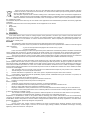
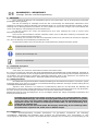
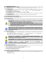
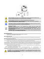
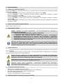
The following symbols are used inside the manual in order to quickly find the most important information:
Information on safety
Procedures to follow
Information/ Suggestions
1.1. Introduction
Dear Customer,
Thank you for having purchasing this product.
The producer, has always paid a great deal of attention to environmental problems, therefore, it has used technologies and
materials with a low environmental impact to manufacture its products in conformity with WEEE – RоHS (2011/65/ЕU and
2012/19/EU community standards.
1.2. Disclaimer
The conformity of the content of these user instructions with hardware and software has been submitted to thorough
verification. Regardless of this, it is still possible for some non-compliance to occur; therefore, no liability will be assumed for
complete conformity.
In the interest of achieving technical perfection, we reserve the right to carry out modifications to the equipment
construction or to data at any time whatsoever. Therefore, we do not accept any liability claims whatsoever attributable to
instructions, figures, drawings or descriptions, without prejudice to errors of any kind.
PRODUCER shall not be held responsible for damages attributable to misuse, improper use, or as a consequence of
unauthorized repairs or modifications.
WARNING! The equipment can be used by children of at least 8 years of age as well as by people with
reduced physical, sensory or mental abilities or by those who lack the necessary experience or
knowledge, as long as they are supervised or after they have received instructions relating to the safe
use of the equipment as well as explanations relating to the use of such equipment.
Children must not play with the equipment. Cleaning and maintenance intended to be carried out by the
user must not be performed by unsupervised children.
1.3. Copyright
These user instructions contain information protected by copyright. It is forbidden to photocopy, duplicate, translate
or record these user instructions on memory equipment, either in whole or in part without prior authorization of PRODUCER.
Any breaches shall be subject to the payment of compensation for any damage caused. All rights are reserved, including
those deriving from the issuing of patents or the registration of utility models.
EN
DOMESTIC HOT WATER HEAT PUMP
Instruction for installation and maintenance

5
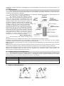
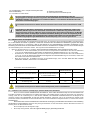
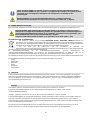
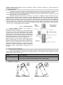
1.4. Operating principle
The equipment is capable of producing domestic hot water mainly by using heat pump technology. A heat pump is
capable of transferring thermal energy from a low temperature source to another with a higher temperature and vice versa.
The equipment uses circuit consisting of a compressor, an evaporator, a condenser and a throttle valve; a liquid/gas
coolant flows inside this circuit (see paragraph 4.6).
The compressor creates a difference in pressure inside the circuit that allows a thermodynamic cycle to be obtained:
this sucks the coolant fluid in through an evaporator, where the fluid itself evaporates at a low pressure by absorbing heat; it
is compressed and driven towards the condenser where the fluid condenses at a high pressure releasing the absorbed heat.
After the condenser, the fluid passes through the so-called “throttle valve” and by losing pressure and the temperature starts
to vaporize, it re-enters the evaporator and the cycle starts all over again.
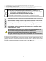
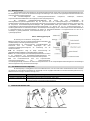
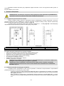
Fig.1 – Operating principle ►
The operating principle of the equipment is as follows
(Fig. 1):
I-II: The coolant fluid sucked in by the compressor, flows inside
the evaporator and while it evaporates, it absorbs the “ecological”
heat given by the air. At the same time, the ambient air is sucked
in by the equipment by a fan; the air loses its heat by passing
over the finned-tube battery of the evaporator;
II-III: The coolant gas passes inside the compressor and it
undergoes an increase in pressure that causes a rise in
temperature; transforming this into superheated steam;
III-IV: Inside the condenser, the coolant gas releases its heat to
the water inside the tank (boiler). This exchange process makes
it possible for the coolant to pass from superheated steam to a
liquid state by condensing at a constant pressure and undergoing
a reduction in temperature;
IV-I: The liquid coolant passes through the throttle valve. It
undergoes a sudden drop in both pressure and temperature and
it partially vaporizes bringing pressure and temperature back to
the initial conditions. The thermodynamic cycle can begin.
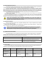
1.5. Available versions and configurations
The heat pump is available in two different versions, in relation to the thermal power (with or without additional heat
exchanger). Each version, in turn, can be set up in different configurations, depending on the possible integrations with other
heating sources (e.g. solar thermal, biomass power, etc.).
Version
Configuration description
HPWH 2.1 200/260 U02
Air source heat pump for the production of domestic hot water
HPWH 2.1 200/260 U02 S
Air source heat pump for the production of domestic hot water suitable for use with the solar
power system or additional heating unit.
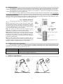
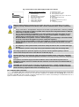
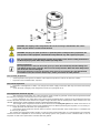
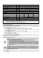
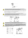
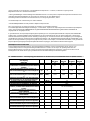
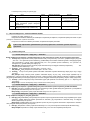
2. TRANSPORT AND HANDLING
Not allowed! Allowed!

6
While handling, do not catch the unit onto upper decorative panels! There is a risk to damage them!
Equipment is delivered on an individual transport pallet.
Use a fork-lift truck or a pallet truck in order to unload the equipment: it is opportune for these to have a load capacity
of at least 400 Kg.
The unpacking operations must be carried out carefully so as not to damage the appliance.
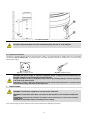
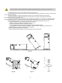
For a transport over short distance (provided that it is done with care), an inclination angle up to 30 degrees is
permitted
It is advised that the maximum permissible inclination angle of 45 degree is not exceeded. If transport in an
inclined position cannot be avoided, the unit should be taken into operation one hour after it has been moved into final
position.
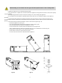
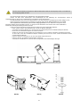
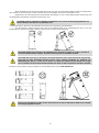
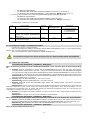
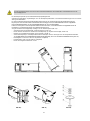
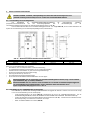
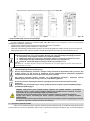
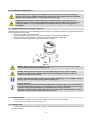
Please follow the described steps bellow in order to mount three supports (fig. 2a):
- Incline the appliance as per Fig. 2a;
- Unscrew the three bolts which hold the pallet to the water heater; Fig.2b
- Mount the adjustable feet directly to the appliance; * Fig.2c
- Put the storage tank in vertical position and adjust the level using the feet.
*If the adjustment feet are delivered in separate parts you can assemble them as follow (fig. 2d):
- put the part 1 on bolt 2 which is unscrewed from the pallet
- put the washer 3 which is removed from the pallet
- Screw on the nuts 4 which are delivered with the appliances
Fig. 2a;
Fig. 2b;
Fig. 2c;
Fig. 2d;

7
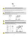
Fig. 2e;
The water heater must (in compliance with Article 20 of Standard EN 60335-1) be fixed to the
ground using the fixing bracket provided for this purpose according to Fig 2e.
After having removed the packaging, make sure that the unit is intact. If in doubt, do not use the equipment and seek
help from authorized technical staff.
In conformity with environmental protection regulations, make sure that all the accessories supplied have been
removed before discarding the packaging.
WARNING! Packaging items (staples, cardboard boxed, etc.) must not be left within the reach of
children as they are dangerous.
(*) Note: at the manufacturer’s discretion, the type of packaging may be subject to change.
For the entire period in which the equipment remains idle, waiting to be used, it is opportune to protect it from
atmospheric agents. Positions permitted for transporting and handling:
WARNING! During the product handling and installation stages, it is forbidden to put the upper part of
the device under any kind of stress whatsoever due to the fact that it is not of a structural nature.
Positions that are not permitted for transporting and handling purposes:
While handling, do not catch the unit onto upper plastic panels! There is a risk to damage them!

8
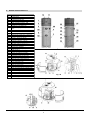
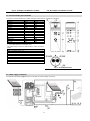
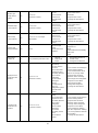
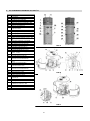
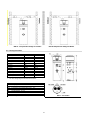
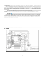
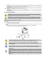
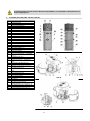
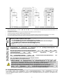
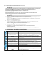
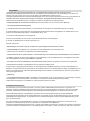
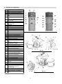
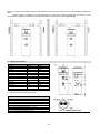
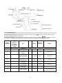
3. DESIGN CHARACTERISTICS
Pos.
1
Heat pump.
2
Control panel.
3
External PVC jacket.
4
Enameled storage tank
5
Upper storage tank probe. “T3”
6
Lower storage tank probe. “T2”
7
Refrigerant recharge needles.
8
Ambient air recirculation fan.
9
Electronically regulated expansion
valve.
10
High-efficiency finned evaporator.
11
Air inlet (∅ 160 mm).
12
Air outlet (∅ 160 mm).
13
Hermetically-sealed rotary compressor.
14
Compressor’s accumulator
15
(1.5 kW – 230 W) El. heater
16
Condenser outlet line - liquid
17
Condenser inlet line – hot gas
18
Replaceable magnesium anode.
19
Hot water outlet connection (G 1”).
20
Recirculation fitting (G ¾”).
21
Evaporator’s distributor
22
Condensates drain (G 3/4”).
23
Solar coil (G 1”)
24
Cold water inlet connection (G1”).
25
50 mm polyurethane insulation.
26
High pressure switch – automatic reset.
27
Safety thermostat, manual reset.
28
Controller box.
29
Probe for solar coil thermosensor.
30
Low pressure switch – automatic reset.
31
4-way defrosting valve
32
Upper decorative panel
33
Back decorative panel
34
Front decorative panel
35
Lower decorative panel (condense trap)
36
Condenser.
37
Protective fan grid
38
Return gas temperature “T5”
39
Coil temperature “T4”
40
Bolts M6x60
41
Ambient temperature “T1”
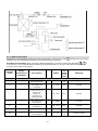
Fig. 3a
Fig. 3b
Fig. 3c

9
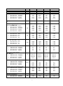
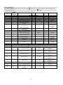
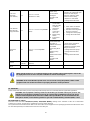
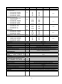
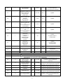
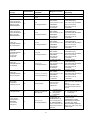
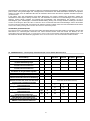
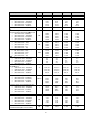
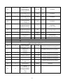
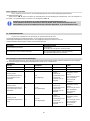
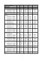
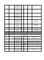
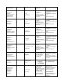
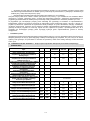
Descriptions
HP2.1 260S
HP2.1 260
HP 2.1 200S
HP2.1 200
Performance data acc. EN16147:2017
Load profile
XL
XL
L
L
Hot water temperature set point
°C
55
55
55
55
Heating up time; th
• (EN 16147:2017 – A20/W55)
• (EN 16147:2017 - A14/W55)
• (EN 16147:2017 - A7/W55)
• (EN 16147:2017 – A2/W55)
h:m
8:05
9:12
10:15
12:26
8:05
9:12
10:15
12:26
7:01
8:07
8:59
10:45
7:01
8:07
8:59
10:45
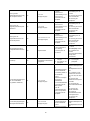
Heating up time in BOOST mode (A7/W10-
55)
h:m
4:21
4:21
3:47
3:47
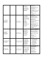
Average heat pump power consumption at
initial heat up Weh-HP / th
• (EN 16147:2017 A40/W55)
• (EN 16147:2017 – A20/W55)
• (EN 16147:2017 - A14/W55)
• (EN 16147:2017 - A7/W55)
• (EN 16147:2017 – A2/W55)
kW
0.462
0.452
0.440
0.420
0.428
0.462
0.452
0.440
0.420
0.428
0.474
0.463
0.451
0.428
0.436
0.474
0.463
0.451
0.428
0.436
Power consumption, standby period; Pes
• (EN 16147:2017 – A20)
• (EN 16147:2017 - A14)
• (EN 16147:2017 - A7)
• (EN 16147:2017 – A2)
kW
0.051
0.052
0.051
0.058
0.051
0.052
0.051
0.058
0.045
0.043
0.042
0.045
0.045
0.043
0.042
0.045
Daily electrical energy consumption; Qelec
• EN 16147:2017 – A20)
• (EN 16147:2017 - A14)
• (EN 16147:2017 - A7)
• (EN 16147:2017 – A2)
kWh
5.138
5.599
6.449
7.847
5.138
5.599
6.449
7.847
3.381
3.765
4.184
5.030
3.381
3.765
4.184
5.030
COPDHW;
• (EN 16147:2017– A20/W55)
• (EN 16147:2017 - A14/W55)
• (EN 16147:2017 - A7/W55)
• (EN 16147:2017 – A2/W55)
-
3.7
3.4
3.0
2.4
3.7
3.4
3.0
2.4
3.4
3.1
2.8
2.3
3.4
3.1
2.8
2.3
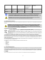
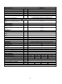
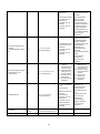
Water heating energy efficiency;
ηWH / ErP class
• (EN 16147:2017– A20/W55)
• (EN 16147:2017 - A14/W55)
• (EN 16147:2017 - A7/W55)
• (EN 16147:2017 – A2/W55)
%
158 / A+
145 / A+
124 / A+
103 / A
158 / A+
145 / A+
124 / A+
103 / A
146 / A+
138 / A+
118 / A+
101 / A
146 / A+
138 / A+
118 / A+
101 / A
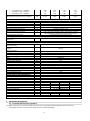
Annual electrical energy consumption; AEC
• (EN 16147:2017– A20/W55)
• (EN 16147:2017 - A14/W55)
• (EN 16147:2017 - A7/W55)
• (EN 16147:2017 – A2/W55)
kWh/a
1059
1154
1354
1628
1059
1154
1354
1628
695
742
867
1012
695
742
867
1012
Maximum volume of mixed water at 40oC
• (EN 16147:2017– A20/W55)
• (EN 16147:2017 - A14/W55)
• (EN 16147:2017 - A7/W55)
• (EN 16147:2017 – A2/W55)
l
352.6
350.4
350.8
349.9
340.3
338.2
338.1
337.8
265
263
262
259
275
273
272
269
Reference hot water temperature; θ’WH
°C
53.7
53.7
53.6
53.6
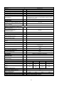
Rated heat output; Prated
• (EN 16147:2017 – A40/W55)
• (EN 16147:2017 – A20/W55)
kW
2.01
1.59
2.01
1.59
1.76
1.39
1.76
1.39

10
• (EN 16147:2017 - A14/W55)
• (EN 16147:2017 - A7/W55)
• (EN 16147:2017 – A2/W55)
1.33
1.20
0.98
1.33
1.20
0.98
1.16
1.05
0.88
1.16
1.05
0.88
Maximal heat output (Summer condition)
kW
2.305
2.305
2.305
2.305
Electrical data
Power supply
V
1/N/220-240
Frequency
Hz
50
Degree of protection
IPX4
HP maximum power consumption
kW
0.663+1,500 (e-heater) = 2,163
Electric heating element power
kW
1.5
Maximum current of appliance
A
3.1+6.5 (e-heater) = 9.6
Max. starting current of heat pump
A
13.5
Required overload protections
A
16A T fuse/ 16A automatic switch, characteristic C (to be
expected during installation on power supply systems)
Internal thermal protection
Safety thermostat with manual reset
Operating conditions
Min.÷ max temperature heat pump air intake
(90% R.H.)
°C
-10 ÷ 43
Min. ÷ max temperature installation site
°C
4 ÷ 40
Working temperature
Reference DHW temperature
(EN 16147:2017)
°C
55
Max. settable water temperature [with E-
heater]
(EN 16147:2017)
°C
65 [75]
Compressor
Rotary
Compressor protection
Thermal circuit breaker with automatic reset
Automatic safety pressure switch (high)
MPa
2.5
Automatic safety pressure switch (low)
MPa
0.1
Fan
Centrifugal
Available external pressure of heat pump
Pa
77
Ejection outlet diameter
mm
160
Nominal air capacity
m3/h
315 (98 Pa)
Motor protection
Internal thermal circuit breaker with automatic reset
Condenser
Aluminium; wrapped externally, not in contact with water
Refrigerant
R134a
Refrigerant charge
g
880
Global warming potential of the refrigerant
1430
CO2 equivalent (CO2e)
t
1287
Defrosting
Active with “4-way valve”
Sound emission data; EN12102:2013
Sound power Lw(A) indoor
dB(A)
53
Automatic anti-Legionella cycle
YES
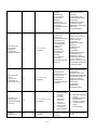
Water storage tank
Descriptions
HP2.1 260S
HP2.1 260
HP 2.1 200S
HP2.1 200
Water storage capacity
l
251
260
194
202
Solar heat exchanger surface
m2
1.2
n.a.
1.0
n.a.
Solar heat exchanger volume
l
7.5
n.a.
5.8
n.a.
Corrosion protection
Mg anode Ø33x400 mm
Thermal insulation
50 mm rigid PU
Maximum working pressure – storage tank
Bar
8
Transport weight
Kg
128
110
121
105
*The output data refers to new appliances with clean heat exchangers!!!
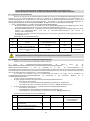
4. IMPORTANT INFORMATION
4.1. Conformity with European regulations
The EVHP heat pump is a device intended for domestic use in conformity with the following European directives:
• 2012/19/ЕU Directive on waste electrical and electronic equipment (WEEE);

11
• 2011/65/EU Directive on the restrictions of use of certain hazardous substances in electric and electronic equipment
(RoHS);
• Directive 2014/30/EU - Electromagnetic compatibility (EMC);
• Directive 2014/35/EU – Low Voltage Directive (LVD);
• Directive 2009/125/EC Eco design Requirements.
4.2. Degrees of protection provided by enclosures
The degree of protection of the equipment is equal to: IPX4.
4.3. Limitations of use.
WARNING!: This device has not been designed, nor is it intended for use within hazardous
environments (due to the presence of potentially explosive atmospheres –according to ATEX standards
or with a requested IP level exceeding that of the equipment) or in applications that require (fault-
tolerant, fail-safe) safety characteristics such as in circuit-breaking systems and/or technologies or in
any other context in which the malfunctioning of an application could cause death or injury to people
or animals or serious damage could be caused to objects or the environment.
N.B.: In the event of a product breakdown or fault, this could cause damage (to people, animals and
goods). It is necessary to arrange for a separate functional monitoring system with alarm functions in
order to avoid such damage being caused. Moreover, it is necessary to arrange for a back-up service
in case of failure!
4.4. Operating limits
The above-mentioned device is intended to be used exclusively for the heating of domestic hot water within the
foreseen limitations of use.
The equipment can only be installed and started up for the intended use within closed heating systems in conformity
with the EN 12828:2012 standard.
N.B.: The manufacturer shall not be held responsible under any circumstances in the event that the
equipment is used for other purposes than for which it has been designed and as regards any
installation errors or equipment misuse.
WARNING! It is forbidden to use the device for purposes other than those intended. Any other use is
to be considered improper and therefore not allowed.
N.B.: During the design and construction stage of the systems, current local rules and provisions are
complied with.
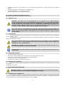
4.5. Fundamental safety rules
• The device must be used by adults;
• Do not open or disassemble the device when this is connected to the power supply;
• Do not touch the device with wet or humid body parts when barefoot;
• Do not pour or spray the device with water;
• Do not stand, sit and/or rest anything on the device.
4.6. Information on coolant used
This device contains fluorinated greenhouse gas included in the Kyoto protocol. Do not discard such gas into the
environment.
Coolant type: HFC-R134a.
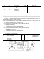
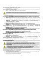
5. INSTALLATION AND CONNECTION
WARNING! Installation, commissioning and maintenance of the device must be performed by qualified
and authorised personnel. Do not attempt to install the device yourself.
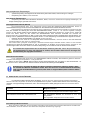
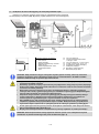
5.1. Preparation of the installation site
The installation of the device must be carried out in a suitable place in order to allow the normal use and adjustment
operations, together with ordinary and extraordinary maintenance to be performed. Therefore, it is important to allow the
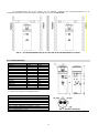
necessary working space by referring to the dimensions, shown in Fig. 4.

12
Fig. 4а - Minimum space and Non-ducted installation. Fig. 4b
X1
X2
X3
Y1
650 mm
650 mm
200 mm
300 mm
Moreover, the premises must:
• Have adequate water and power supply lines;
• Be available and ready for connection to the condense drain;
• Be available and ready with adequate discharge pipes in case of damage caused to the boiler or actuation of the safety
valve or breakage of pipes/connections;
• Have containment systems in case of serious water leaks;
• Be sufficiently lit (where appropriate);
• Not measure less than 20 m3;
• Be frost-proof and dry.
• Be horizontally installed or with small incline backwards: 1 … 3o see Fig 4b
WARNING! In order to avoid the propagation of mechanical vibrations, do not install the equipment on
floor slabs with wooden beams (e.g. in lofts).
WARNING! In order to avoid short circulation of air between inlet / outlet, always use two elbows
mounted in opposite direction when non-ducted installation is done! Fig.4
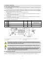
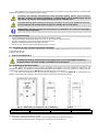
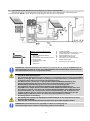
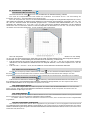
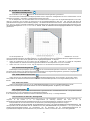
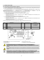
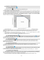
5.2. Ventilation connection
Apart from the space indicated in paragraph 5.1, the heat pump requires adequate ventilation.
It is necessary to create a dedicated air duct as indicated in the illustration (Fig. 5).
Moreover, it is important to ensure an adequate ventilation of the premises where the equipment is to be installed.
An alternative solution is indicated in the following illustration (Fig. 5a): this consists of a second duct that draws air
in from outside instead of directly from inside the premises.

13
Fig. 5 – Example of an air outlet duct Fig. 5a - Example of dual duct connection
Carry out the installation of each air duct taking care that:
• The weight of such does not adversely affect the equipment itself;
• Maintenance operations can be carried out;
• This is adequately protected so as to avoid the accidental intrusion of material inside the equipment itself;
• The maximum total allowable pressure drops for all components, including through holes for mounting on external wall,
within the pipe system must not exceed 77 Pa.
All Technical parameters shown in the table above, are guaranteed at air flow rate 315 m3/h at pressure
98Pa. So Please keep the following rules:
1. Use airduct pipe system with diameter Ø160mm
2. Maximum length of both inlet and outlet straight pipes must not exceed 12 meters!!!
3. Each elbow 90o, is equal to 2 m straight pipe.
4. Elbow 45o, is equal to 1.5 m straight pipe.
Examples:
four elbows 90o + 4m straight pipes, or two elbows 90o + 8m straight pipes, four elbows 45o + 6m straight pipes.
During operation, the heat pump tends to lower the ambient temperature if the external air duct is not
carried out.
An appropriate protection grid must be installed in line with the discharge pipe conveying air to the
outside with the aim of avoiding foreign bodies from entering the equipment. In order to guarantee
maximum device performance, the grid chosen must ensure low pressure loss.
In order to avoid the formation of condensate: insulate the air discharge pipes and the air duct cover
connections with steam-tight thermal cladding of an adequate thickness.
If it is considered necessary in order to prevent flow noise, sound mufflers can be mounted.
Fit the pipes, the wall through holes and the connections to the heat pump with vibration damping
systems.
WARNING! the simultaneous operation of an open-flue firebox (e.g. an open-flue fireplace) together with the heat
pump causes a dangerous environmental pressure drop. This could cause the backflow of exhaust gas into the
environment itself.
Do not operate the heat pump together with an open-flue firebox.
Use only sealed-chamber fireboxes (approved) with a separate duct for combustion air.
Keep the doors to the boiler room closed and hermetically sealed if they do not have a combustion air supply in
common with inhabited areas.
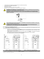
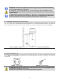
5.3. Particular installation conditions
One of the peculiarities of the heat pump heating system is represented by the fact that these units cause a
considerable reduction of the air temperature that is generally ejected from inside the home. Apart from being colder than the
ambient air, the exhaust air is also completely dehumidified; for this reason, it is possible to allow the air to flow back into the
home in order to cool specific environments or rooms during the summer.
Installation consists of the splitting of the discharge pipe to which two shutters are applied with the aim of directing
the air flow either towards the outside or the inside of the home (Fig. 6a, 6b).

14
Fig. 6a - Example of installation in summer Fig. 6b Example of installation in winter
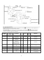
5.4. Device mounting and connection
The device must be installed on a stable, flat floor surface that is not subject to vibration.
Dimensions [±5mm]
260
200
h [mm]
2010
1720
a [mm]
1285
994
b [mm]
834
724
d [mm]
1285
995
f [mm]
1064
803
i [mm]
781*
681*
k [mm]
60
60
n [mm]
766*
681*
u [mm]
1440
1153
w [mm]
58
58
R [mm]
2055
1785
ØD [mm]
630
630
ØDF [mm]
160
160
M [mm]
260
260
* - for models with heat exchanger only!
The table below shows the characteristics of the connection
points.
CW - cold water inlet - G1"
HW - hot water outlet - G1"
IS - solar flow - G1"
OS - solar return - G1"
TS - thermosensor - G 1/2"
R - recirculation - G 3/4"
EE - opening for electrical element - G 11/2
MA - Mg anodes - G11/4
CD – condense drainage – G3/4
Fig. 7 – Overall dimensions
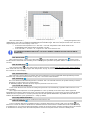
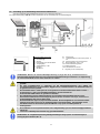
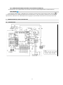
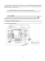
5.5. Water supply connections
The following illustration (Fig. 8) shows an example of a water supply connection.

15
Fig. 8 Connections to the water supply net and solar collector
Fig 8a
Obligatory elements to be installed:
1. Water inlet pipe
2. Shut-off valve
3. Inlet water pressure regulator
4. Back flow preventing valve
5. Safety valve – 8 Bar
6. Safety valves drainage
7. Safety valves drainage
8. Tank drainage valve
10. Expansion vessel
11. Solar Safety valve – 6 Bar
12. Solar expansion vessel.
15. Recirculating pump; I max = 5A (solar or
recirculation
16. Thermostatic mixing valve
17. Flow switch
18. External thermosensor (solar or
recirculation)
E. Heat pump controller
When the water hardness is particularly high (higher than 25°F), it is recommended to use a water
softener, properly calibrated and monitored; in this case the residual hardness should not fall below
15°F.
• Usage of this device at temperature and pressure level above prescribed leads to warranty violation!
• This device is intended for heating of potable water in liquid state. Using different fluids in different
states leads to warranty violation!
• Device’s heat exchangers are intended for use with circulating clean water and mixture of it plus
Propylene GLYCOL at liquid state. The presence of anticorrosion additives is obligatory. Using
different fluids in different states leads to warranty violation!
• Dissimilar Metals cause galvanic corrosion. Therefore pipes, joints and fittings of dissimilar metals
should be connected to the appliance by means of dielectric separators.
• Plastic pipes (PP) are permeable to oxygen. It is forbidden to connect the heat exchanger to system
made by PP pipes as well as to open circulation system! Abusing this rule will lead to corrosion
inside tube.
• It is obligatory for the system installer to fit an 8-bar safety valve No5 on the cold water intake pipe
(Fig. 8).
• It is forbidden a presence of any stop valves, taps between the safety valve and storage tank!
The safety equipment for protection against over pressure must be operated regularly in order to
remove limescale deposits and to check that it is not blocked (Fig. 8)
The drain pipe No6, connected to the safety valve must be installed sloping continuously downwards
and, in a place, where it is protected against the formation of ice (Fig. 8). Using a tundish is obligatory
(Fig.8a)
An expansion vessel No10 (Fig.8) should be installed in order to absorb water expansion due to
temperature variation. Pressure regulator No3 and expansion vessel should be calculated together by
qualified person.
WARNING! The heat pump for the production of domestic hot water is capable of heating water up to
more than 65°C. For this reason, as a protection against burns, it is necessary to install an automatic
thermostat mixing equipment No16 to the hot waterpipe (Fig. 8)
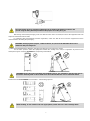
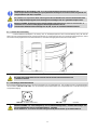
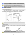
5.6. Condense drain connections
Condensate, that forms during the operation of the heat pump, flows through an appropriate discharge pipe (G 3/4”)
that passes inside cladding and it comes out on the side of the equipment. Use flexible hose Ø16 (69, fig. 9) to connect it to
the plastic nipple 68. This plastic part 68, should be handle with care in order to avoid damages. Connected the hose to a
siphon so that the condensate can flow freely (Fig. 9).

16
Fig. 9 - Example of condensate drain connection via siphon
The plastic nipple No68 (fig.9) should be manipulated gently, by hand, to avoid damages!
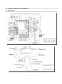
5.7. Electrical connections
The device is supplied already wired for the main power supply. It is powered through a flexible cable and a socket/plug
combination (Fig. 10 and Fig. 10a). An earthed Schuko socket with separate protection is needed for the connection to the
mains power supply.
Fig. 10 –A Schuko socket
Fig. 10a –Equipment plug
WARNING! The power supply to which the equipment will be connected must be protected by an
adequate residual current circuit breaker at least: 16A/230V
The type of residual current circuit breaker must be chosen by evaluating the type of electric equipment
to be used on the entire system.
With reference to the connection to the main power supply and the safety equipment (e.g. residual current
circuit breaker) comply with standard IEC 60364-4-41.
6. COMMISSIONING.
WARNING! Check that the equipment is connected to the earth cable.
WARNING! Check that the line voltage corresponds to that indicated on the equipment identification
plate.
WARNING! Do not exceed the maximum permitted pressure indicated in the “general technical data”
section; 8 Bar
WARNING! Check that the water circuit safety valve is working;
The commissioning procedure must be carried out by performing the following procedures:

17
6.1. Filling the tank with water.
Fill the boiler by opening inlet tap No2 (Fig. 8) and the tap hot water of your bathroom. The tank is fully filled with water,
when only water without air starts leaking trough the tap in the bathroom. Check that there are no leaks from gaskets and
connections. Tighten the bolts or connections where necessary;
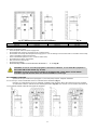
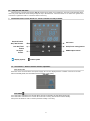
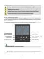
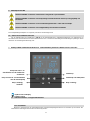
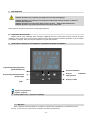
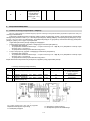
7. OPERATING MODES. USER INTERFACE. INITIAL CONTROLLER ADJUSTMENT.
- Display Symbol; - Button symbol
7.1. User interface – Buttons and their function explanation.
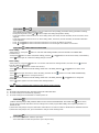
7.1.1. Power ‘ON’
When the unit is connected to the main power supply, all icons are displayed on the controller screen for 3 seconds.
After functionality check, the unit enters into the “standby” mode (OFF):
“Standby”
7.1.2. button
Press this button and hold it for 2 seconds when the unit is in standby, the unit will be turned ‘ON’.
Press this button and hold it for 2 seconds when the unit is running, the unit will be turned standby.
Short press this button to enter or exit the parameter setting or checking.
DOWN adjust button
Clock/Timer setting button
Set button
UP adjust
button
Unit ‘ON’/’OFF’
button
Electrical heater
‘ON’/’OFF’ button

18
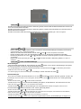
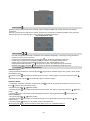
7.1.3. buttons And
- These are the multi-purpose buttons. They are used for the temp setting, parameter setting, parameter checking,
clock adjustment and adjustment of the timer.
- During running status, press or button to adjust the setting temperature directly.
- Press these buttons when the unit is on clock setting status, the hour(s) and the minute(s) of the clock time can be
adjusted.
- Press these buttons when the unit is on timer setting status, the hour(s) and the minute(s) of the timer ‘ON’/’OFF’
can be adjusted.
- Press and buttons at the same time and hold for 5 seconds, the buttons are locked.
- Press and buttons at the same time and hold for 5 seconds again, the buttons are unlocked.
7.1.4. button - TIMER AND CLOCK SETTING
Clock setting:
- After power on, short press button to enter the clock setting interface, hour and minute icons “88:88” flash
simultaneously;
- Short press button to switch hour/minute setting, press the and buttons to set the exact hour(s) and minute(s);
- Press button again to confirm the settings/changes and exit.
Timer setting:
- After power on, long press button for 5 seconds to enter the timer setting interface, the timer on icon and hour
icon “88:” flash simultaneously;
- Press the and buttons to set the exact hour(s).
- Press button to transfer to minute setting, minute icon “:88” flash, press the and buttons to set the exact
minute(s).
- Press button again to transfer to timer off setting, the timer off icon and hour icon “88:” flash simultaneously.
- Press the and buttons to change the hour(s).
- Press button to transfer to minute setting, minute icon “:88” flash, press the and buttons to change the
minute(s).
- Press button again to save and exit the timer setting interface.
Press button to cancel the timer, while the “timer setting” mode is active!!!
NOTE:
1) The timer ‘ON’ and timer ‘OFF’ functions can be set at the same time.
2) The timer settings are automatically repeating.
3) The timer settings are still valid after a sudden power cut.
7.1.5. button
1) When the heat pump is ON, press this button to turn ‘ON’ the electrical heater. The heater icon will be shown,
and the electrical heater will start to work according to the control program after “delay” time elapsed (parameter 3 –
default 30 min).
2) When the heat pump is ON, press this button and hold for 5 seconds to enable or disable the fan ventilation function.
3) When the heat pump is OFF, press this button to entry E-heater heating mode.
7.1.6. button
1) Check the temperatures and EXV open steps
-Press this button to enter temp and EXV open step checking.

19
-Press the and buttons to check the temp sensor values and EXV open steps (parameters A-F).
2) Check the system parameters (from 1 to 35)
-In any status, press this button and hold for 5 seconds, entry the system parameter checking interface.
-Press the and buttons to check the system parameters.
3) Adjust the system parameters. See 8.2. “Parameter list”
If no action is performed using the buttons for 10 seconds, the controller will exit and save the setting
automatically.
NOTE: The parameters have been set; the user cannot change the parameters optionally. Please ask a qualified
service person to do this when required.
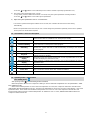
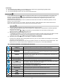
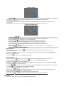
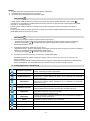
7.2. User interface - LED icons description
Hot water available
The icon indicates that the domestic hot water temperature has reached the set
point. The hot water is available for use. Heat pump is standby
Fan ventilation
The icon indicates that the fan ventilation function is enabled.
Electrical heating
The icon indicates that the electrical heating function is enabled. The electrical
heater will work according to the control program.
Defrosting
The icon indicates that the defrosting function is enabled. This is an automatic
function; the system will enter or exit the defrosting according to the internal
control program
Heating
The icon indicates that the unit is operating in Heating mode.
Key lock
The icon indicates the key lock function is enabled. The keys Will be deactivated
until this function is disabled
Left temperature
display
The display shows the set water temperature. In case any malfunction occurs, this
section will display the related error code.
Right temperature
display
When checking or adjusting the parameters, this section will display the related
parameter value
Time display
The display shows the clock time or timer time.
Timer ‘ON’
The icon indicates that the timer ‘ON’ function is enabled.
Timer ‘OFF’
The icon indicates that the timer ‘OFF’ function is enabled.
Error
The icon indicates there is a malfunction.
7.3. Operating modes - main function
7.3.1. Heating mode -
After pressing button , “Normal heating mode is activated.
Water temperature difference for compressor starting is used to control the compressor on or off. (Parameter 1 “water
temp. difference TS6”)
When lower tank temperature T2 is less than set temperature TS1-TS6, the compressor will work to heat the water
until reaching the set temperature “TS1 set”. “TS1 set” is an adjustable one by the user via main control display – Max value
by default is 65oC. In this mode if the ambient air temperature Т1 ≤ -10°C or > 44°C the compressor will turn OFF and
Electric heater will turn ON. If the ambient temperature Т1 arises to ≥ -8°C or < 42°C, Electric heater will turn OFF and
compressor will be turned ON.
Strona się ładuje...
Strona się ładuje...
Strona się ładuje...
Strona się ładuje...
Strona się ładuje...
Strona się ładuje...
Strona się ładuje...
Strona się ładuje...
Strona się ładuje...
Strona się ładuje...
Strona się ładuje...
Strona się ładuje...
Strona się ładuje...
Strona się ładuje...
Strona się ładuje...
Strona się ładuje...
Strona się ładuje...
Strona się ładuje...
Strona się ładuje...
Strona się ładuje...
Strona się ładuje...
Strona się ładuje...
Strona się ładuje...
Strona się ładuje...
Strona się ładuje...
Strona się ładuje...
Strona się ładuje...
Strona się ładuje...
Strona się ładuje...
Strona się ładuje...
Strona się ładuje...
Strona się ładuje...
Strona się ładuje...
Strona się ładuje...
Strona się ładuje...
Strona się ładuje...
Strona się ładuje...
Strona się ładuje...
Strona się ładuje...
Strona się ładuje...
Strona się ładuje...
Strona się ładuje...
Strona się ładuje...
Strona się ładuje...
Strona się ładuje...
Strona się ładuje...
Strona się ładuje...
Strona się ładuje...
Strona się ładuje...
Strona się ładuje...
Strona się ładuje...
Strona się ładuje...
Strona się ładuje...
Strona się ładuje...
Strona się ładuje...
Strona się ładuje...
Strona się ładuje...
Strona się ładuje...
Strona się ładuje...
Strona się ładuje...
Strona się ładuje...
Strona się ładuje...
Strona się ładuje...
Strona się ładuje...
Strona się ładuje...
Strona się ładuje...
Strona się ładuje...
Strona się ładuje...
Strona się ładuje...
Strona się ładuje...
Strona się ładuje...
Strona się ładuje...
Strona się ładuje...
Strona się ładuje...
Strona się ładuje...
Strona się ładuje...
Strona się ładuje...
Strona się ładuje...
Strona się ładuje...
Strona się ładuje...
Strona się ładuje...
Strona się ładuje...
Strona się ładuje...
Strona się ładuje...
Strona się ładuje...
Strona się ładuje...
Strona się ładuje...
Strona się ładuje...
Strona się ładuje...
Strona się ładuje...
Strona się ładuje...
Strona się ładuje...
Strona się ładuje...
Strona się ładuje...
Strona się ładuje...
Strona się ładuje...
Strona się ładuje...
Strona się ładuje...
Strona się ładuje...
Strona się ładuje...
Strona się ładuje...
Strona się ładuje...
Strona się ładuje...
Strona się ładuje...
Strona się ładuje...
-
 1
1
-
 2
2
-
 3
3
-
 4
4
-
 5
5
-
 6
6
-
 7
7
-
 8
8
-
 9
9
-
 10
10
-
 11
11
-
 12
12
-
 13
13
-
 14
14
-
 15
15
-
 16
16
-
 17
17
-
 18
18
-
 19
19
-
 20
20
-
 21
21
-
 22
22
-
 23
23
-
 24
24
-
 25
25
-
 26
26
-
 27
27
-
 28
28
-
 29
29
-
 30
30
-
 31
31
-
 32
32
-
 33
33
-
 34
34
-
 35
35
-
 36
36
-
 37
37
-
 38
38
-
 39
39
-
 40
40
-
 41
41
-
 42
42
-
 43
43
-
 44
44
-
 45
45
-
 46
46
-
 47
47
-
 48
48
-
 49
49
-
 50
50
-
 51
51
-
 52
52
-
 53
53
-
 54
54
-
 55
55
-
 56
56
-
 57
57
-
 58
58
-
 59
59
-
 60
60
-
 61
61
-
 62
62
-
 63
63
-
 64
64
-
 65
65
-
 66
66
-
 67
67
-
 68
68
-
 69
69
-
 70
70
-
 71
71
-
 72
72
-
 73
73
-
 74
74
-
 75
75
-
 76
76
-
 77
77
-
 78
78
-
 79
79
-
 80
80
-
 81
81
-
 82
82
-
 83
83
-
 84
84
-
 85
85
-
 86
86
-
 87
87
-
 88
88
-
 89
89
-
 90
90
-
 91
91
-
 92
92
-
 93
93
-
 94
94
-
 95
95
-
 96
96
-
 97
97
-
 98
98
-
 99
99
-
 100
100
-
 101
101
-
 102
102
-
 103
103
-
 104
104
-
 105
105
-
 106
106
-
 107
107
-
 108
108
-
 109
109
-
 110
110
-
 111
111
-
 112
112
-
 113
113
-
 114
114
-
 115
115
-
 116
116
-
 117
117
-
 118
118
-
 119
119
-
 120
120
-
 121
121
-
 122
122
-
 123
123
-
 124
124
-
 125
125


Tesy AquaThermica 260 S Instrukcja instalacji
- Typ
- Instrukcja instalacji
- Niniejsza instrukcja jest również odpowiednia dla
w innych językach
- Deutsch: Tesy AquaThermica 260 S Installationsanleitung
- English: Tesy AquaThermica 260 S Installation guide
- Nederlands: Tesy AquaThermica 260 S Installatie gids
Inne dokumenty
-
 Kaisai KHX-16PY3 Instrukcja obsługi
-
Nibe NIBE GBM 10-15 Installer And User Manual
-
 SolarPower SP4002 Installation and Owner's Manual
-
STIEBEL ELTRON WPKI-Set Operation Instruction
-
 Kratki MSK Instrukcja obsługi
-
Sony DSC-W55 Instrukcja obsługi
-
-
Kampmann Room thermostat, type 30155 Instrukcja instalacji
-
EUROSTER 11W Instrukcja obsługi
-
Gorenje TC120ZNT Instrukcja obsługi


