Samsung SCC-B2033B Instrukcja obsługi
- Kategoria
- Kamery ochrony
- Typ
- Instrukcja obsługi

ENG
DIGITAL COLOR CAMERA
user manual
SCC-B2333(P)
SCC-B2033P
imagine the possibilities
Thank you for purchasing this Samsung product.
To receive more complete service,
please register your product at
www.samsungsecurity.com
ENG RUS
POL
CZE
TUR

2 – DIGITAL COLOR CAMERA
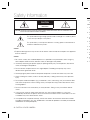
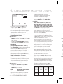
Safety information
CAUTION
RISK OF ELECTRIC SHOCK.
DO NOT OPEN
CAUTION: TO REDUCE THE RISK OF ELECTRIC SHOCK, DO NOT REMOVE REAR COVER. NO USER SERVICEABLE PARTS
INSIDE. REFER TO QUALIFIED SERVICE PERSONNEL..
This symbol indicates high voltage is present inside. It is dangerous to make any kind of
contact with any inside part of this product.
This symbol alerts you that important literature concerning operation and maintenance
has been included with this product.
WARNING
To prevent damage which may result in fi re or electric shock hazard, do not expose this appliance
to rain or moisture.
WARNING
Be sure to use only the standard adapter that is specifi ed in the specifi cation sheet. Using any
other adapter could cause fi re, electrical shock, or damage to the product
Incorrectly connecting the power supply or replacing battery may cause explosion, fi re, electric
shock, or damage to the product.
Do not connect multiple cameras to a single adapter. Exceeding the capacity may cause
abnormal heat generation or fi re.
Securely plug the power cord into the power receptacle. Insecure connection may cause fi re.
When installing the camera, fasten it securely and fi rmly. A falling camera may cause personal
injury.
Do not place conductive objects (e.g. screwdrivers, coins, metal things, etc.) or containers fi lled
with water on top of the camera. Doing so may cause personal injury due to fi re, electric shock,
or falling objects.
Do not install the unit in humid, dusty, or sooty locations. Doing so may cause fi re or electric
shock.
If any unusual smells or smoke come from the unit, stop using the product. In such case,
immediately disconnect the power source and contact the service center. Continued use in such
a condition may cause fi re or electric shock.
If this product fails to operate normally, contact the nearest service center. Never disassemble
or modify this product in any way. (SAMSUNG is not liable for problems caused by unauthorized
modifi cations or attempted repair.)
•
1.
2.
3.
4.
5.
6.
7.
8.
9.
W
e
CAUT
D
s
D
1
I
f
o
R
c
K
In
A
d
A
v
T
10.
1.
2.
3.
4.
5.
6.
7.
8.
9.

English – 3
ENG
d of
nce
nce
y
c
ed
k,
uch
e
zed
Safety information
When cleaning, do not spray water directly onto parts of the product. Doing so may cause fi re or
electric shock.
CAUTION
Do not drop objects on the product or apply strong shock to it. Keep away from a location
subject to excessive vibrationor magnetic interference.
Do not install in a location subject to high temperature (over 50°C), low temperature (below -
10°C), or high humidity. Doing so may cause fi re or electric shock.
If you want to relocate the already installed product, be sure to turn off the power and then move
or reinstall it.
Remove the power plug from the outlet when then there is a lightning. Neglecting to do so may
cause fi re or damage to the product.
Keep out of direct sunlight and heat radiation sources. It may cause fi re.
Install it in a place with good ventilation.
Avoid aiming the camera directly towards extremely bright objects such as sun, as this may
damage the CCD image sensor.
Apparatus shall not be exposed to dripping or splashing and no objects fi lled with liquids, such as
vases, shall be placed on the apparatus.
The Mains plug is used as a disconnect device and shall stay readily operable at any time.
10.
1.
2.
3.
4.
5.
6.
7.
8.
9.

4 – DIGITAL COLOR CAMERA
Important Safety Instructions
Read these instructions.
Keep these instructions.
Heed all warnings.
Follow all instructions.
Do not use this apparatus near water.
Clean only with dry cloth.
Do not block any ventilation openings. Install in accordance with the manufacturer’s instructions.
Do not install near any heat sources such as radiators, heat registers, or other apparatus (including
amplifi ers) that produce heat.
Do not defeat the safety purpose of the polarized or grounding-type plug. A polarized plug has two blades
with one wider than the other. A grounding type plug has two blades and a third grounding prong. The wide
blade or the third prong is provided for your safety. If the provided plug does not fi t into your outlet, consult
an electrician for replacement of the obsolete outlet.
Protect the power cord from being walked on or pinched particularly at plugs,
convenience receptacles, and the point where they exit from the apparatus.
Only use attachments/accessories specifi ed by the manufacturer.
Use only with cart, stand, tripod, bracket, or table specifi ed by the manufacturer, or
sold with the apparatus.
Unplug this apparatus when a card is used. Use caution when moving the cart/
apparatus combination to avoid injury from tip-over.
Refer all servicing to qualifi ed service personnel. Servicing is required when the apparatus has been
damaged in any way, such as powersupply cord or plug is damaged, liquid has been spilled or objects have
fallen into the apparatus, the apparatus has been exposed to rain or moisture, does not operate normally, or
has been dropped.
1.
2.
3.
4.
5.
6.
7.
8.
9.
10.
11.
12.
13.
14.

English – 5
ENG
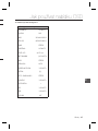
Contents
Introduction
Features 6
PRODUCT & ACCESSORIES 7
Part Names and Functions 8
Installation
Connecting the Auto Iris Lens Connector 11
Mounting the lens 11
Connecting cables and checking operation 12
How to use OSD Menu
Using Icons in the Menu 13
Main Menu 13
Profi le 14
Camera Setup 16
Intelligence 22
Privacy Zone Setup
24
Other Set 25
Communication 26
System Information 26
Language 26
Specifi cations
Specifi cations 28
es
wide
sult
have
y, or

6 – DIGITAL COLOR CAMERA
Introduction
FEATURES
High Resolution
This camera has realized high resolution of 600 lines using the top-notch full digital image processing and
special algorithm technologies.
Intelligent Motion Detection & Tracking
This is an intelligent function that automatically detects a motion of an object. You can set a virtual fence so it
sounds an alert if an object passes / enters /exits the virtual fence or virtual area.
XDR (eXtended Dynamic Range)
Actively controls the gamma compensation in the way it operates the ambient luminance contrast in a
certain pixel unit to determine the optimal visibility.
DAY/NIGHT
This function can make the IR Cut fi ltering function inactive under the illumination below the normal value.
High Sensitivity
It implements images of high sensitivity using the up-to-date SONY Super-HAD IT CCD..
Low Illumination
It uses the digital signal technologies such as low illumination and Day/Night functions that make your camera
identify objects even in the worst environment.
Superior Backlight Adjustment
When an object has a bright illumination or sunlight behind it, this camera automatically improves the
shaded object picture quality.
Digital Power Synchronization
The full digital Line Lock function directly adjusts the vertical camera synchronization to enhance the
operationability and reliability of this camera.
Output Signal Setting
You can set the following Video output signals: Image reversion (Horizontal, Vertical, or both), Privacy,
Horizontal/Vertical profi ling, and digital zooming.
OSD(On Screen Display) Menu
OSD menu is provided to display the status of camera and to confi gure the functions interactively.
Coaxial Cable Communication
This is a remote control function that overlaps the coaxial cable (for a transfer of the video signal) with the
control signal. In installation or repair, this helps you control the communication controller (optional) without
additional cabling.
❖
•
❖
•
❖
•
❖
•
❖
•
❖
•
❖
•
❖
•
❖
•
❖
•
❖
•
PRO
P❖
•
Came
•

English – 7
ENG
Introduction
and
t
e.
ra
t
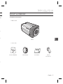
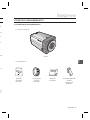
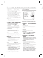
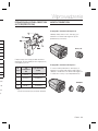
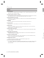
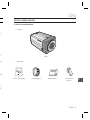
PRODUCT & ACCESSORIES
Product & Accessories❖
Accessories
•
Camera
Camera Holder(Mount)
Auto Iris
Lens Connector
User’s Manual
Main Product
•
C Mount Adapter

8 – DIGITAL COLOR CAMERA
Introduction
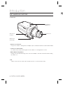
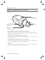
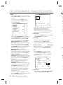
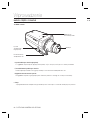
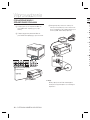
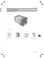
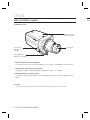
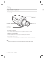
PART NAMES AND FUNCTIONS
Side View❖
Auto Iris Lens Connector
This groove is used for screwing the mount adapter, a part of the bracket where the camera will be installed.
Auto Iris Lens Control Cable
This cable transmits the power and signals from the camera for controlling the Auto Iris Lens.
Mount Adapter Fixing Grooves
These grooves are used when fi xing screws of the mount adapter connected to the bracket when installing
the camera on it.
•
•
•
Note :
When the camera lens becomes dirty, softly clean it with a lens tissue or a cloth soaked in pure ethanol.
–
Mount Adapter
Fixing Grooves
Camera Lens
Auto Iris Lens
Connector
Auto Iris Lens
Control Cable
R❖

English – 9
ENG
Introduction
alled.
ing
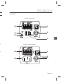
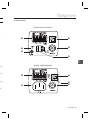
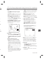
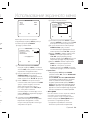
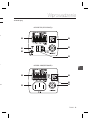
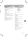
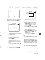
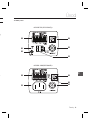
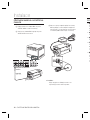
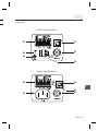
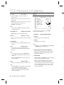
Rear Panel❖
n
o
r
q
p
s
<AC24/DC12V (B2333(P))>
n
o
q
s
<AC220V~240V(SCC-B2033P)>
p

10 – DIGITAL COLOR CAMERA
Introduction
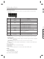
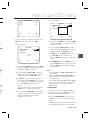
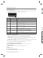
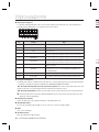
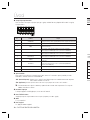
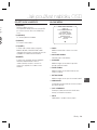
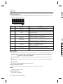
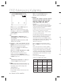
n Input/Output Connector
This connector has input and output ports for RS-485 control signals, DAY/NIGHT switching, and alarm
output signals.
No. Function Description
1 ALARM OUT
Alarm out port for motion detection. (Open collector type)
2 GND Grounding Port.
3 GND Grounding Port.
4 SHUTTER (S0)
This is a port for selecting an external high speed shutter mode.
If connected in LOW (0V), it will become ON inside.
5 SHUTTER (S1)
This is a port for selecting an external high speed shutter mode.
If connected in LOW (0V), it will become ON inside.
6 SHUTTER (S2)
This is a port for selecting an external high speed shutter mode.
If connected in LOW (0V), it will become ON inside.
7 5V OUT
Power supply port for RS-485 JIG. Use within typical DC +5V 100mA
8
DAY/NIGHT IN
This is a port for DAY&NIGHT conversion.
High(DC +3V~+5V) : DAY(COLOR) Mode,
Low(0V) : NIGHT(BW) Mode
9 RS-485 DATA-
This is a port for connection to RS-485 DATA- signal line.
10 RS-485 DATA+
This is a port for connection to RS-485 DATA+ signal line.
o SETUP Switch
This switch is used to set the function or property. When this switch is pressed for at least 2 seconds, the
MAIN MENU appears.
ef
(Left/Right)
: By pressing this switch left or right, you can move left or right on the menu or change the
displayed value.
cd
(Up/Down) :
By pressing this switch up or down, you can move up or down on the menu.
: When you press this switch in the menu, the selected function is confi rmed. To enter a submenu, press
this button.
p Power Display LED
When the power is normally connected, the red LED lights.
q Video OUT Port
This is connected to the Video Input Port of the monitor and it outputs the Video signals.
r GND
This is a grounding port.
s Power Connection Port
This is connected to the Power cable.
CO
CO
Conn
the A
P
N
1
2
3
4
No
–

English – 11
ENG
he
e the
ress
Installation
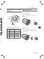
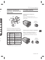
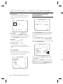
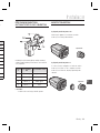
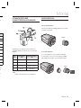
CONNECTING THE AUTO IRIS LENS
CONNECTOR
Connect each uncovered shutter control cables to
the Auto Iris Lens Connector as the following
Pin
No.
DC Control
Type
Video Control Type
1 Damp(-) Power (+12V)
2 Damp(+) Not applicable
3 Drive(+) Video Signal
4 Drive(-) Ground
Note :
You can switch a control type of the lens in the menu.
–
MOUNTING THE LENS
When using the CS lens
Mount the CS lens by rotating it clockwise as shown
in the picture:
When using the C lens
After mounting the C-mount adapter by rotating it
clockwise, turn the C lens clockwise until it is fi xed as
shown in the picture.
CS lens
C lens

12 – DIGITAL COLOR CAMERA
Installation
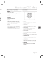
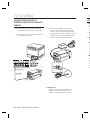
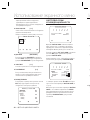
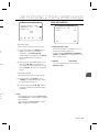
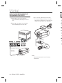
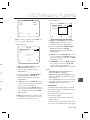
CONNECTING CABLES AND
CHECKING OPERATION
①
Connect one end of the BNC cable to the
VIDEO OUT Port on the rear of the camera.
② Connect another end of the BNC cable to the
VIDEO IN Port on the monitor.
③
Finally connect the power adapter to the
camera. You can connect 2 lines of the power
adapter to the camera using the Slot Head
screwdriver as shown in the picture.
(GND: cable with the white stripe line)
1 2
3 4
5 6
7
8
1
.
A
L
A
R
A
M
O
U
T
2
.
G
N
D
3
.
G
N
D
4
.
S
H
U
T
T
E
R
(
S
O
)
5
.
S
H
U
T
T
E
R
(S
1
)
6
.
S
H
U
T
T
E
R
(S
2
)
7
.
5
V
O
U
T
8
.
D
A
Y
/
N
I
G
H
T
I
N
Note :
Connect any power source of AC 24V and DC 12V
irrespective of polarity.
–
1
2
3
4
5
6
7
8
1
.
A
L
A
R
A
M
O
U
T
2
.
G
N
D
3
.
G
N
D
4
.
S
H
U
T
T
E
R
(
S
O
)
5
.
S
H
U
T
T
E
R
(
S
1
)
6
.
S
H
U
T
T
E
R
(
S
2
)
7
.
5
V
O
U
T
8
.
D
A
Y
/
N
I
G
H
T
I
N
Video In Terminal of Monitor Rear
Surface
BNC cable
Video Out Terminal
USI
E
B
sa
R
R
U
P
O
e
U
P
O
re
•
•
•
•
•

English – 13
ENG
wer
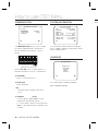
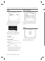
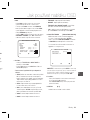
USING ICONS IN THE MENU
(EXIT)
Exits the menu setting.
Before you exits the menu setting, select SAVE to
save your settings, or select QUIT to cancel.
(RET)
Returns to the previous menu.
(HOME)
Returns to the main menu.
(SAVE)
Used to save your settings of MASK AREA,
PRIVACY ZONE and more.
Once you save your settings, they will remain
even if you select QUIT in the menu.
(DEL)
Used to deletes your settings of MASK AREA,
PRIVACY ZONE and more.
Once you delete your settings, they will not be
restored even if you select QUIT in the menu.
•
•
•
•
•
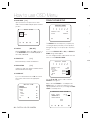
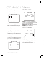
MAIN MENU
ÃÃMAIN MENUÃÃ
PROFILE
CAMERA SET
INTELLIGENCE
PRIVACY ZONE
OTHER SET
COMMUNICATION
SYSTEM INFO
LANGUAGE
PROFILE
You can set a mode according to the camera
installation conditions.
CAMERA SET
Confi gure Camera related functions and data.
INTELLIGENCE
You can confi gure the settings of motion
detection, tracking and more.
PRIVACY ZONE
You can confi gure the privacy related settings.
OTHER SET
You can confi gure for Factory Defaults, and more.
COMMUNICATION
Confi gures the settings regarding the RS-485
communication.
SYSTEM INFO.
Displays the system information including the
camera version and communication settings.
LANGUAGE
Select a preferred one from the supported
languages.
•
•
•
•
•
•
•
•
How to use OSD Menu

14 – DIGITAL COLOR CAMERA
How to use OSD Menu
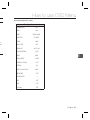
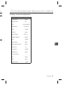
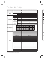
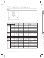
PROFILE
e
PROFILE
f
Ã
STANDARD
ITS
BACKLIGHT
DAY/NIGHT
GAMING
CUSTOM
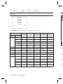
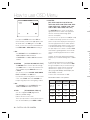
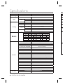
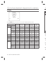
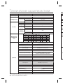
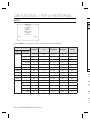
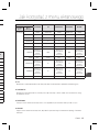
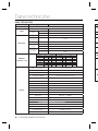
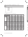
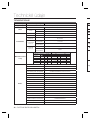
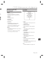
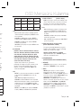
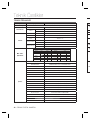
In the PROFILE menu, you can confi gure the following camera settings at once.
CAMERA SET Menu
STANDARD ITS BACKLIGHT DAY/NIGHT GAMING
Previous
Menu
Sub-menus
IRIS ALC ALC ALC ALC ALC
ALC -- ---
LENS DC DC DC DC DC
LEVEL 0 0 0 0 0
BACKLIGHT OFF OFF BLC OFF OFF
MOTION (F.FAST)--- (F.FAST)--- NORM (F.FAST)--- SLOW
DNR MID MID MID MID MID
SHUTTER OFF AUTO1/250 OFF OFF OFF
SENS-UP AUTOx4 AUTOx2 AUTOx4 AUTOx4 AUTOx4
XDR MID MID MID MID MID
DAY/
NIGHT
AUTO AUTO DAY AUTO DAY
NIGHT - - - - -
BURST OFF ON OFF OFF OFF
EXT -- ---
BURST OFF ON OFF OFF OFF
Pr
M
W
D
IT
It w
B
It w
D
It w
G
It w
❖
❖
❖
❖

English – 15
ENG
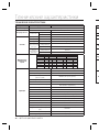
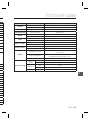
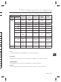
How to use OSD Menu
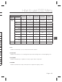
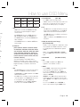
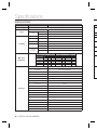
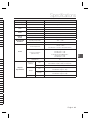
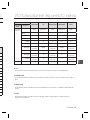
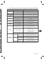
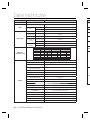
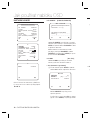
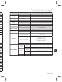
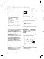
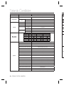
CAMERA SET Menu
STANDARD ITS BACKLIGHT DAY/NIGHT GAMING
Previous
Menu
Sub-menus
WHITE
BAL
DAY DAY/NIGHT DAY DAY/NIGHT DAY
DAY -- ---
MODE ATW2 ATW1 ATW1 ATW1 ATW1
RED00 000
BLUE 0 0 0 0 0
NIGHT - - - - -
BRIGHTNESS
User setting
allowed
MID
User setting
allowed
MID
User setting
allowed
MODE OFF ATW2 OFF ATW2 OFF
RED
User setting
allowed
0
User setting
allowed
0
User setting
allowed
BLUE
User setting
allowed
0
User setting
allowed
0
User setting
allowed
DETAIL 2 2 2 2 2
ITS
It will be set automatically so you can easily check the traffi c conditions.
BACKLIGHT
It will be set automatically so you can distinguish the object from the background in a severe backlighting scene.
DAY/NIGHT
It will be set automatically so it optimizes to the day or night conditions, respectively.
GAMING
It will be set automatically to help you take a picture in a regular indoor lighting condition.
❖
❖
❖
❖

16 – DIGITAL COLOR CAMERA
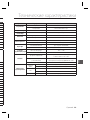
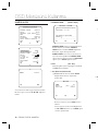
How to use OSD Menu
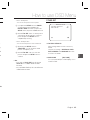
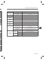
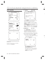
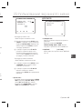
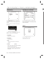
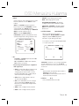
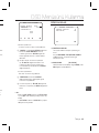
CAMERA SETUP
eCAMERA SETf
CAMERA ID OFF
IRIS ALC
MOTION (F.FAST)---
DNR MID
SHUTTER OFF
SENS-UP AUTO X4
FLICKERLESS (OFF)---
XDR MID
d
c
DAY/NIGHT AUTO
WHITE BAL
DIGITAL ZOOM
OFF
DETAIL [2]
V-SYNC INT
AGC COLOR SUP
LOW
REVERSE OFF
POSI/NEGA +
PIP OFF
d
c
DIS OFF
Setup the general functions of zoom camera module.
Use the
cdef
switch to select a menu item.
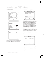
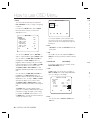
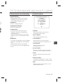
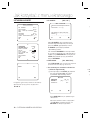
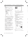
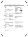
CAMERA ID [OFF, ON]
CAMERA ID
ABCDEFGHIJKLMNOPQRSTUVWXYZ0
123456789 :?-+*()/
SP
ffee
SP LOCATION
CAMERA-1..................
...........................
The CAMERA ID menu is used for you to assign
a unique name to a camera. If you press the
SETUP switch with the CAMERA ID menu
selected, you will see the appropriate screen.
You can enter up to 54 alphanumeric or
special characters for the CAMERA ID. Select
LOCATION and press the SETUP switch to
move the display position of the CAMERA ID.
IRIS [ALC, ELC]
The IRIS menu is used if you want to adjust the
intensity of radiation incoming to the camera.
ALC (Automatic Light Control)
① If you press the SETUP switch with an ALC-
based sub menu selected, you will see the
appropriate screen.
ALC
LENS DC
LEVEL [00]----I----
BACKLIGHT OFF
The LENS menu is used if you select a type of
the AI lens.
For normal operation, you must select DC for a
DC-type lens, and select VIDEO for a VIDEO-
type lens.
❖
❖
•
②
EL
①
•

English – 17
ENG
How to use OSD Menu
sign
ct
D.
he
LC-
e
e of
or a
O-
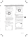
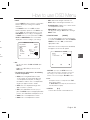
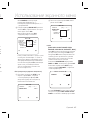
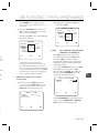
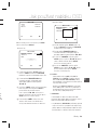
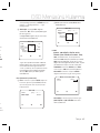
The LEVEL menu is used to adjust the
overall brightness, where “+” will increase the
brightness and “–” will decrease it.
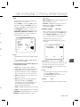
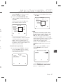
② If you set the BACKLIGHT option to BLC,
you will see a menu where you can set the
BLC area.
you can set the desired BLC zone by defi ning
the size and location.
ALC
LENS DC
LEVEL [00]----I----
BACKLIGHT BLC
AREA USER
<SIZE>
<LOCATION>
If you use an ordinary camera in a scene
with an intensive backlight, the object will be
displayed dark on the monitor affected by the
backlight. To solve this problem, you can use
the BLC(Back Light Compensation) function
to improve the sharpness of the image in
such a high contrast scene.
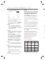
ELC (Electronic Light Control)
①
If you press the SETUP switch when the ELC
submenu is selected, the corresponding screen
appears. You can make the ELC (Electronic Light
Control) function active or not.
ELC
LEVEL [00]----I----
BACKLIGHT OFF
•
② In similar to ALC setting, you can specify the
BLC area.
ELC
LEVEL [00]----I----
BACKLIGHT BLC
AREA USER
<SIZE>
<LOCATION>
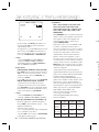
AGC
[OFF, VERY LOW, LOW, MID, HIGH, VERY
HIGH, USER, FIX]
The AGC (Auto Gain Control) menu is used to
set the AGC level of the camera. When the AGC
is active, the camera automatically increases the
sensitivity by amplifying the Video signal when
the strength of the signal falls below the normal
value.
If OFF or FIX mode is selected in the SENS-UP
menu, you can specify the AGC level.
If you press the SETUP switch with a USER
sub menu selected, you will see the appropriate
screen.
AGC USER
LEVEL [16]
In USER mode, you can break down the level in
16 steps from VERY LOW to VERY HIGH to your
preference.
❖

18 – DIGITAL COLOR CAMERA
How to use OSD Menu
AGC FIX
LEVEL [01]
If you press the SETUP switch with a FIX sub
menu selected, you will see the appropriate screen.
As a fi xed value of the AGC gain is used in FIX
mode, you can select one of the 16 detailed levels
from VERY LOW to VERY HIGH before fi xing it.
Note :
If the DAY/NIGHT menu of the CAMERA SET is set to
AUTO, the AGC menu will be deactivated.
If FLICKERLESS is set to ON, the AGC FIX mode will be
disabled.
MOTION
[S.SLOW, SLOW, NORM, FAST, F.FAST]
The MOTION menu is used to adjust the strength
of the AGC level for a control of the camera motion.
This is available only if the SENS-UP menu is set
to AUTO.
You can select one from S.SLOW, SLOW, NORM,
FAST and F.FAST for the AGC level.
If you monitor a fast moving object in a low contrast
scene, select F.FAST while select S.SLOW for a
hardly moving object in the same lighting condition.
Note :
If the DAY/NIGHT menu of the CAMERA SET is set to
AUTO, the MOTION menu will be deactivated.
DNR
[OFF,LOW,MID,HIGH, USER(1~16)]
You can confi gure the DNR (Digital Noise
Reduction) related settings.
Reduces the noise on the screen.
This is especially useful for a severely distorted screen.
You can set the level if you set DNR to USER.
–
–
❖
–
❖
SHUTTER
[OFF, AUTO 1/100(PAL:1/120), AUTO 1/250,
AUTO 1/500, AUTO 1/1000, AUTO 1/2000, AUTO
1/4000, AUTO 1/10K , 1/100(PAL:1/120), 1/250,
1/500, 1/1000, 1/2000, 1/4000, 1/10K , EXT]
The SHUTTER menu is used to set the fi xed
high-speed electronic shutter, auto high speed
electronic shutter and external high speed
electronic shutter(EXT).
You can select one of 7 options from 1/100(PAL:1/120)
to 1/10K for the fi xed high speed electronic shutter,
which is mostly used for imaging a fast moving object.
The auto high speed electronic shutter operates
as the fi xed high speed shutter in a high contrast
scene but automatically focuses the target if the
iris opens fully in a low contrast scene like in ELC
mode. When it gets brighter back, the mode will
switch to the fi xed high speed electronic shutter
mode.
However, the auto high speed shutter operates
properly only in a camera featuring a DC or VIDEO
lens.
In external high speed electronic shutter (EXT)
mode, you can select one of 8 modes from OFF
through 1/100(PAL:1/120) to 1/10K for the high
speed electronic shutter. It works as the high
speed electronic shutter. You can select an
option using SHUTTER(S0), SHUTTER(S1) and
SHUTTER(S2) on the rear.
Connect each of the terminals to GND.
See the below table for the operation.
SHUTTER(S0) SHUTTER(S1) SHUTTER(S2)
OFF
(NTSC: 1/60,
PAL:1/50)
OFF OFF OFF
1/100
(PAL:1/120)
ON OFF OFF
1/250 OFF ON OFF
1/500 ON ON OFF
1/1000 OFF OFF ON
❖
No
S
[O
X
X
X
X
F
F
A
d
e
b
m
No
–
–
–
–
❖
–
–
–
–

English – 19
ENG
How to use OSD Menu
UTO
0,
d
/120)
r,
ect.
es
ast
e
LC
will
er
s
DEO
FF
h
d
R(S2)
F
F
F
F
1/2000 ON OFF ON
1/4000 OFF ON ON
1/10K ON ON ON
Note :
If IRIS mode is set to ELC, the SHUTTER menu will be
deactivated as you adjust the brightness using the
electronic shutter.
If the SENS-UP function is set to AUTO, only items of
OFF and AUTO are available in the SHUTTER menu.
If the SENS-UP mode is set to FIX, the SHUTTER menu
will be deactivated.
If the FLICKERLESS function is set to ON, the SHUTTER menu
will be deactivated.
SENS-UP
[OFF, AUTO X2, AUTO X4, AUTO X6, AUTO
X8, AUTO X12, AUTO X16, AUTO X24, AUTO
X32, AUTO X48, AUTO X64, AUTO X96, AUTO
X128, AUTO X256, AUTO X512, FIX X2, FIX
X4, FIX X6, FIX X8, FIX X12, FIX X16, FIX X24,
FIX X32, FIX X48, FIX X64, FIX X96, FIX X128,
FIX X256, FIX X512]
Automatically detects the ambient level of
darkness in the dark or low contrast scene to
extend the accumulated time, keeping the image
bright and sharp; It can be also used as FIX
mode.
Note :
If the SHUTTER option is set to fi xed electronic shutter or
EXT mode, the SENS-UP menu will be deactivated.
If FLICKERLESS is set to ON, the FIX mode of the SENS-
UP menu will be disabled.
If the IRIS menu is set to ELC, the electronic shutter will
control the brightness so the SENS-UP function can not
be set to FIX mode, but to OFF or AUTO mode.
If the SHUTTER menu is set to AUTO, the SENS-UP
menu can be set to either OFF or AUTO mode.
–
–
–
–
❖
–
–
–
–
FLICKERLESS [OFF, ON]
If set to ON, the shutter speed will be fi xed to
1/100(PAL:1/120) second. This will prevent possible screen
distortion due to a mismatch between the vertical sync
frequency and the blinking frequency of the lighting.
Note :
If the IRIS function is set to ELC, the Flickerless menu will
be deactivated. If the SHUTTER menu is set to AUTO, FIX
or EXT mode, the Flickerless menu will be deactivated.
If the SENS-UP function is set to FIX mode, the Flickerless
menu will be deactivated.
If AGC is set to FIX mode, the FLICKERLESS function will
be disabled.
XDR (eXtended Dynamic Range)
[OFF, LOW, MID, HIGH]
Actively controls the gamma compensation in the
way it operates the ambient luminance contrast
in a certain pixel unit to determine the optimal
visibility.
Select one from OFF, LOW, MID and HIGH.
Closing to HIGH will increase the compensation
level.
DAY/NIGHT
[DAY,NIGHT,AUTO,EXT]
DAY
If set to DAY, it will be fi xed to DAY mode
regardless of the ambient conditions.
NIGHT
If set to NIGHT, it will be fi xed to Black-and-White
mode regardless of the ambient conditions.
If you press the SETUP switch with a NIGHT sub
menu selected, you will see a menu where you can
set Burst to OFF/ON.
If BURST is set to ON, the Burst signal will output
together with the black-and-white composite video
signal. If BURST is set to OFF, the Burst signal does
not output.
You can set the BURST option to OFF/ON, or
select to output the Burst signal in NIGHT mode.
❖
–
–
–
❖
❖
•
•

20 – DIGITAL COLOR CAMERA
How to use OSD Menu
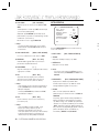
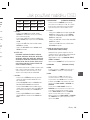
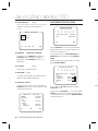
AUTO
The camera will automatically switch between
DAY and NIGHT mode, according to the lighting
condition.
If you press the SETUP switch with an AUTO-
based sub menu selected, you will see the
appropriate screen.
AUTO
BURST OFF
DAYÆNIGHT
BRIGHTNESS MID
DWELL TIME 2S
NIGHTÆDAY
BRIGHTNESS MID
DWELL TIME 5S
MASK AREA 1 2
You can set the BURST option to OFF/ON, or
select to output the Burst signal in NIGHT mode.
You can select from LOW, MID and HIGH for
the brightness of DAYÆNIGHT, which is a
brightness level in switching from the color fi lter
to Black-and-White. Closing to LOW from HIGH
will switch the fi lter in a low contrast scene.
The DWELL TIME of DAYÆNIGHT is a time
required to determine the need for switching the
fi l t e r .
You can select from LOW, MID and HIGH for
the brightness of NIGHTÆDAY, which is a
brightness level in switching from the Black-and-
White fi lter to color. Closing to LOW from HIGH
will switch the fi lter in a low contrast scene.
The DWELL TIME of NIGHTÆDAY is a time
required to determine the need for switching the
fi l t e r .
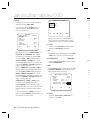
The MASK menu is used to prevent a fi lter
switch error or inability of determining the switch
in existence of a high spot light source at night.
If you press the SETUP switch in item 1 or 2 of
the MASK menu, you will see a menu where you
can specify an area to mask.
•
MASK AREA
<SIZE>
<LOCATION>
You can specify Mask 1 and 2 simultaneously.
The mask is used only for determining the fi lter
switch and any excessive bright area at night will
be masked.
Note :
If BACKLIGHT is set to BLC, the MASK AREA function will
be deactivated.
EXT
This enables an auto switch between DAY and
NIGHT mode using the interface with the external
sensor.
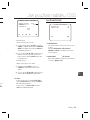
WHITE BAL [DAY/NIGHT]
If you want to adjust the color scheme, use the
WHITE BALANCE function.
DAY
In DAY mode, you can set the color values of
RED and BLUE. The screen will be displayed in
colors according to your settings.
WHITE BAL
DAY/NIGHT DAY
MODE AWC
RED [00]----I----
BLUE [00]----I----
R-GAIN [0248]
B-GAIN [0247]
Note :
You can set the values of R-GAIN and B-GAIN only in
AWC mode.
–
•
❖
•
–
NI
U
b
lu
If
b
if
D
In
B
d
No
Fo
5
•
–
–
–
•
•
•
•
•
Strona się ładuje...
Strona się ładuje...
Strona się ładuje...
Strona się ładuje...
Strona się ładuje...
Strona się ładuje...
Strona się ładuje...
Strona się ładuje...
Strona się ładuje...
Strona się ładuje...
Strona się ładuje...
Strona się ładuje...
Strona się ładuje...
Strona się ładuje...
Strona się ładuje...
Strona się ładuje...
Strona się ładuje...
Strona się ładuje...
Strona się ładuje...
Strona się ładuje...
Strona się ładuje...
Strona się ładuje...
Strona się ładuje...
Strona się ładuje...
Strona się ładuje...
Strona się ładuje...
Strona się ładuje...
Strona się ładuje...
Strona się ładuje...
Strona się ładuje...
Strona się ładuje...
Strona się ładuje...
Strona się ładuje...
Strona się ładuje...
Strona się ładuje...
Strona się ładuje...
Strona się ładuje...
Strona się ładuje...
Strona się ładuje...
Strona się ładuje...
Strona się ładuje...
Strona się ładuje...
Strona się ładuje...
Strona się ładuje...
Strona się ładuje...
Strona się ładuje...
Strona się ładuje...
Strona się ładuje...
Strona się ładuje...
Strona się ładuje...
Strona się ładuje...
Strona się ładuje...
Strona się ładuje...
Strona się ładuje...
Strona się ładuje...
Strona się ładuje...
Strona się ładuje...
Strona się ładuje...
Strona się ładuje...
Strona się ładuje...
Strona się ładuje...
Strona się ładuje...
Strona się ładuje...
Strona się ładuje...
Strona się ładuje...
Strona się ładuje...
Strona się ładuje...
Strona się ładuje...
Strona się ładuje...
Strona się ładuje...
Strona się ładuje...
Strona się ładuje...
Strona się ładuje...
Strona się ładuje...
Strona się ładuje...
Strona się ładuje...
Strona się ładuje...
Strona się ładuje...
Strona się ładuje...
Strona się ładuje...
Strona się ładuje...
Strona się ładuje...
Strona się ładuje...
Strona się ładuje...
Strona się ładuje...
Strona się ładuje...
Strona się ładuje...
Strona się ładuje...
Strona się ładuje...
Strona się ładuje...
Strona się ładuje...
Strona się ładuje...
Strona się ładuje...
Strona się ładuje...
Strona się ładuje...
Strona się ładuje...
Strona się ładuje...
Strona się ładuje...
Strona się ładuje...
Strona się ładuje...
Strona się ładuje...
Strona się ładuje...
Strona się ładuje...
Strona się ładuje...
Strona się ładuje...
Strona się ładuje...
Strona się ładuje...
Strona się ładuje...
Strona się ładuje...
Strona się ładuje...
Strona się ładuje...
Strona się ładuje...
Strona się ładuje...
Strona się ładuje...
Strona się ładuje...
Strona się ładuje...
Strona się ładuje...
Strona się ładuje...
Strona się ładuje...
Strona się ładuje...
Strona się ładuje...
Strona się ładuje...
Strona się ładuje...
Strona się ładuje...
Strona się ładuje...
Strona się ładuje...
Strona się ładuje...
Strona się ładuje...
Strona się ładuje...
Strona się ładuje...
Strona się ładuje...
Strona się ładuje...
Strona się ładuje...
Strona się ładuje...
Strona się ładuje...
Strona się ładuje...
Strona się ładuje...
Strona się ładuje...
Strona się ładuje...
Strona się ładuje...
-
 1
1
-
 2
2
-
 3
3
-
 4
4
-
 5
5
-
 6
6
-
 7
7
-
 8
8
-
 9
9
-
 10
10
-
 11
11
-
 12
12
-
 13
13
-
 14
14
-
 15
15
-
 16
16
-
 17
17
-
 18
18
-
 19
19
-
 20
20
-
 21
21
-
 22
22
-
 23
23
-
 24
24
-
 25
25
-
 26
26
-
 27
27
-
 28
28
-
 29
29
-
 30
30
-
 31
31
-
 32
32
-
 33
33
-
 34
34
-
 35
35
-
 36
36
-
 37
37
-
 38
38
-
 39
39
-
 40
40
-
 41
41
-
 42
42
-
 43
43
-
 44
44
-
 45
45
-
 46
46
-
 47
47
-
 48
48
-
 49
49
-
 50
50
-
 51
51
-
 52
52
-
 53
53
-
 54
54
-
 55
55
-
 56
56
-
 57
57
-
 58
58
-
 59
59
-
 60
60
-
 61
61
-
 62
62
-
 63
63
-
 64
64
-
 65
65
-
 66
66
-
 67
67
-
 68
68
-
 69
69
-
 70
70
-
 71
71
-
 72
72
-
 73
73
-
 74
74
-
 75
75
-
 76
76
-
 77
77
-
 78
78
-
 79
79
-
 80
80
-
 81
81
-
 82
82
-
 83
83
-
 84
84
-
 85
85
-
 86
86
-
 87
87
-
 88
88
-
 89
89
-
 90
90
-
 91
91
-
 92
92
-
 93
93
-
 94
94
-
 95
95
-
 96
96
-
 97
97
-
 98
98
-
 99
99
-
 100
100
-
 101
101
-
 102
102
-
 103
103
-
 104
104
-
 105
105
-
 106
106
-
 107
107
-
 108
108
-
 109
109
-
 110
110
-
 111
111
-
 112
112
-
 113
113
-
 114
114
-
 115
115
-
 116
116
-
 117
117
-
 118
118
-
 119
119
-
 120
120
-
 121
121
-
 122
122
-
 123
123
-
 124
124
-
 125
125
-
 126
126
-
 127
127
-
 128
128
-
 129
129
-
 130
130
-
 131
131
-
 132
132
-
 133
133
-
 134
134
-
 135
135
-
 136
136
-
 137
137
-
 138
138
-
 139
139
-
 140
140
-
 141
141
-
 142
142
-
 143
143
-
 144
144
-
 145
145
-
 146
146
-
 147
147
-
 148
148
-
 149
149
-
 150
150
-
 151
151
-
 152
152
-
 153
153
-
 154
154
-
 155
155
-
 156
156
-
 157
157
-
 158
158
-
 159
159
-
 160
160


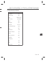
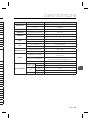
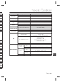
Samsung SCC-B2033B Instrukcja obsługi
- Kategoria
- Kamery ochrony
- Typ
- Instrukcja obsługi
w innych językach
- slovenčina: Samsung SCC-B2033B Používateľská príručka
- Türkçe: Samsung SCC-B2033B Kullanım kılavuzu
Powiązane artykuły
-
Samsung SCC-B2335P/CDM Instrukcja obsługi
-
Samsung SCC-B5368SBP Instrukcja obsługi
-
Samsung SCC-B5398P Instrukcja obsługi
-
-
-
-
-
Samsung SCC-A2013P Instrukcja obsługi
-