
1
RS108
v1.4
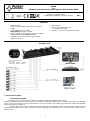
RS108 10-port switch with power supply for 8 IP cameras, RACK
PL
Edition: 5 from 18.11.2019
Supercedes the edition: 4 from 13.09.2019 EN**
Features:
Switch 10 ports
8 PoE ports 10/100Mb/s (data transfer and power
supply)
2 ports 10/100Mb/s (UP LINK)
Long Range mode (up to 250m)
30 W for each PoE port, supports devices complaint
with the IEEE802.3af/at (PoE+) standard
Supports auto-learning and auto-aging of MAC
addresses (1K size)
LED indication
Metal enclosure RACK 19” 1U
- color black RAL 9005
warranty – 2 year from the production date
Example of use.
1. Technical description
1.1. General description.
The RS108 is a 10-ports switch in a RACK 19” metal housing with integrated power supply.
Automatic detection of any devices powered in the PoE/PoE+ standard is enabled at the 1 – 8 ports of the switch. The UP LINK
ports is used for connection of another network device via RJ45 connector. The LEDs at the front panel indicate the operation
status (description in the table 4).
The PoE technology ensures a network connection and reduces installation costs by eliminating the need to supply a
separate power cable for each device. This method allows supplying other network devices, such as IP phone, wireless access
point or router.

2
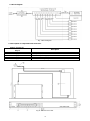
1.2 Block diagram.
Fig. 1. Block diagram.
1.3. Description of components and connectors.
Table 1. (see Fig. 2)
Element no.
(Fig. 2)
Description
[1]
2 x UP LINK port
[2]
8 x PoE port (1÷8)
[3]
Switch mode power supply for the switch 52 V DC/2,3 A/120 W
[4]
230 V power cord
[5]
Switch of mode Long Range
Fig. 2. The enclosure view.

3
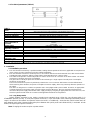
1.4. Technical parameters (Table 3.)
Table 3.
Ports
10 10/100Mb/s ports (8 x PoE + 2 x UP LINK)
with connection speed auto-negotiation and MDI/MDIX Auto Cross
PoE power supply
IEEE 802.3af/at (1÷8 ports), 52 V DC / 30 W at each port *
Long Range mode
Long Range, VLAN
Protocols, Standards
IEEE802.3, 802.3u, 802.3x CSMA/CD, TCP/IP
Bandwidth
1,6Gbps
Transmission method
Store-and-Forward
Optical indication of
operation
Switch power supply;
Link/Act;
PoE Status
Power supply
~100-240 V; 50/60Hz; 1,5 A
Operating conditions
temperature -10°C ÷ 40°C,
relative humidity 5% - 90%, no condensation
Mounting dimensions
W=19” H=1U D=227
Dimensions
W=482 W
1
=440 H=44 D=227 [+/-2mm]
Enclosure
RACK 19″ 1U, Steel plate, DC01 1,0mm color RAL 9005
Gross/Net weight
2,6/2,8 kg
Protection class
EN 60950-1:2007
II (second)
Storage temperature
-20°C ÷ 60°C
Declarations
CE
* The given value of 30 W per port is the maximum value. The total power consumption should not exceed 96 W.
2. Installation
2.1. Installation procedure
1. The unit should be mounted by a qualified installer, holding relevant permits and licenses (applicable and required for a
given country) for 230 V interference and low-voltage installations.
2. The unit should be mounted in confined spaces, in accordance with the 2nd environmental class, with normal relative
humidity (RH=90% maximum, without condensation) and temperature from -10°C to +40°C.
3. The switch shall operate in a horizontal position in order to ensure free air convection in the Rack cabinet. The switch
load balance should be done prior to installation.
The given value of 30 W per port is the maximum value referring to a single output. The total power consumption
should not exceed 96 W.
The increased demand for power is particularly evident in the case of cameras with heaters or infrared illuminators -
when launching these features, the power consumption increases rapidly, which may adversely affect the operation of
the switch.
The device is designed for a continuous operation and is not equipped with a power-switch. Therefore, an appropriate
overload protection in the power supply circuit should be provided. Moreover, the user should be informed how to
disconnect the power supply unit from the mains supply (usually by assigning an appropriate fuse in the fuse box). The
electrical system shall be made in accordance with applicable standards and regulations.
2.2. Long Range mode
Switch enables operation in two modes: standard and extended range. When the Long Range switch is in
STANDARD position (see Fig. 5), PoE ports operate at 100 Mb / s up to 100 meters. After switching to EXTEND position,
range is increased to 250 meters and speed is reduced to 10 Mb / s. Additionally, VLAN function, which isolates the PoE
ports between each other (communication takes place between the UpLink ports and individual PoE), is activated. In both
modes, the UpLink port speed is 100 Mb / s.
Note: Changing the modes requires a power restart!

4
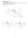
2.3. Installation procedure
1. Mount the switch in a RACK 19 ” cabinet.
2. Connect the plug of the power supply switch to the 230 V socket.
Make sure that the device is installed in such a manner and place, that the free flow of air around the device is ensured.
3. Connect the power (230 V).
4. Connect the camera wires to the RJ45 connectors (PoE connectors).
5. Check the optical indication of the switch operation.
Connection schemes

5
3. Operation indication.
Table 4. Operation indication
OPTICAL INDICATION AT THE PoE PORTS (1÷8)
DIODA LED ZIELONA (PoE)
Indication of the PoE power
supply at the RJ45 ports
OFF- no power supply at the RJ45 port (the device is not connected or not compliant with
the IEEE802.3af/at standard)
ON – supply at the RJ45 port
Blinking – short-circuit or output overload
YELLOW LED LIGHT (LINK)
The connection status of LAN
devices, 10/100Mb/s
and data transmission
OFF- no connection
ON - the device is connected; 10/100Mb/s
Blinking – data transmission
OPTICAL INDICATION AT THE UP LINK PORTS
GREEN LED LIGHT
Port on the left side:
No lit - no voltage
Lit – switch operates properly
Port on the right side:
No lit – switch operates in normal mode
Lit– Long Range mode active
YELLOW LED LIGHT (LINK)
The connection status of
LAN devices, 10/100Mb/s
and data transmission
OFF- no data transmission
ON - the device is connected: 10/100Mb/s
Blinking – data transmission
WEEE LABEL
Waste electrical and electronic equipment must not be disposed of with normal household waste.
According to the European Union WEEE Directive, waste electrical and electronic equipment should be
disposed of separately from normal household waste
.
Pulsar sp. j.
Siedlec 150, 32-744 Łapczyca, Poland
Tel. (+48) 14-610-19-40, Fax. (+48) 14-610-19-50
e-mail: biuro@pulsar.pl, sales@pulsar.pl
http:// www.pulsar.pl, www.zasilacze.pl
-
 1
1
-
 2
2
-
 3
3
-
 4
4
-
 5
5


w innych językach
- English: Pulsar RS108 Operating instructions
Powiązane dokumenty
-
Pulsar S108 Instrukcja obsługi
-
-
-
-
-
-
-
-
-